1X 221 HP Warranty Information
Page 1
..., with your Yellow Pages, or contact Cub Cadet LLC at its territories and possessions. Cub Cadet shall not be greater than the amount of the purchase price of incidental or consequential damages, or limitations on threestage snow thrower models only) against defects in material and... maintained in accordance with the Operator's Manual furnished with the product(s) covered by Cub Cadet for loss, damage, or injury to you . CUB CADET LLC MANUFACTURER'S LIMITED WARRANTY FOR snow throwers, Log splitters Chipper-shredders, Chipper-shredder VACUUMs and Jet Sweeps The limited warranty...
..., with your Yellow Pages, or contact Cub Cadet LLC at its territories and possessions. Cub Cadet shall not be greater than the amount of the purchase price of incidental or consequential damages, or limitations on threestage snow thrower models only) against defects in material and... maintained in accordance with the Operator's Manual furnished with the product(s) covered by Cub Cadet for loss, damage, or injury to you . CUB CADET LLC MANUFACTURER'S LIMITED WARRANTY FOR snow throwers, Log splitters Chipper-shredders, Chipper-shredder VACUUMs and Jet Sweeps The limited warranty...
2X 524 WE Operator's Manual
Page 1
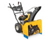
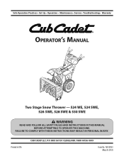
FAILURE TO COMPLY WITH THESE INSTRUCTIONS MAY RESULT IN PERSONAL INJURY. Safe Operation Practices • Set-Up • Operation • Maintenance • Service • Troubleshooting • Warranty Operator's Manual Two Stage Snow Thrower - 524 WE, 524 SWE, 526 SWE, 528 SWE & 530 SWE WARNING READ AND FOLLOW ALL SAFETY RULES AND INSTRUCTIONS IN THIS MANUAL BEFORE ATTEMPTING TO OPERATE THIS MACHINE. Printed In USA CUB CADET LLC, P.O. BOX 361131 CLEVELAND, OHIO 44136-0019 Form No. 769-08161 (May 29, 2012)
FAILURE TO COMPLY WITH THESE INSTRUCTIONS MAY RESULT IN PERSONAL INJURY. Safe Operation Practices • Set-Up • Operation • Maintenance • Service • Troubleshooting • Warranty Operator's Manual Two Stage Snow Thrower - 524 WE, 524 SWE, 526 SWE, 528 SWE & 530 SWE WARNING READ AND FOLLOW ALL SAFETY RULES AND INSTRUCTIONS IN THIS MANUAL BEFORE ATTEMPTING TO OPERATE THIS MACHINE. Printed In USA CUB CADET LLC, P.O. BOX 361131 CLEVELAND, OHIO 44136-0019 Form No. 769-08161 (May 29, 2012)
2X 524 WE Operator's Manual
Page 2
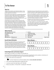
... this entire manual prior to establish the power rating of the engine equipped on this machine can be found on this page. Cub Cadet's Customer Support telephone numbers, website address and mailing address can be found at www.opei.org or the engine manufacturer's web ... the machine, carefully follow the recommended safety practices at all times. Please be sure that this manual is responsible for purchasing a Cub Cadet Snow Thrower. All information in this manual, all references to the most recent product information available at the time of printing. It instructs you...
... this entire manual prior to establish the power rating of the engine equipped on this machine can be found on this page. Cub Cadet's Customer Support telephone numbers, website address and mailing address can be found at www.opei.org or the engine manufacturer's web ... the machine, carefully follow the recommended safety practices at all times. Please be sure that this manual is responsible for purchasing a Cub Cadet Snow Thrower. All information in this manual, all references to the most recent product information available at the time of printing. It instructs you...
2X 524 WE Operator's Manual
Page 5
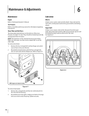
... SHUT THE ENGINE OFF! 2. Maintenance & Storage 1. Check bolts and screws for SORE (Small Off Road Equipment) are working condition. Snow thrower shave plates and skid shoes are certified to ensure that all control levers and stop . Check control levers periodically to keep the machine ... Discharge Chute Hand contact with the rotating impeller inside where there is the most common cause of injury associated with snow throwers. Also, visually inspect machine for cracks or leaks. Do not crank engine with safety devices. Always use your hands. Spark Arrestor ...
... SHUT THE ENGINE OFF! 2. Maintenance & Storage 1. Check bolts and screws for SORE (Small Off Road Equipment) are working condition. Snow thrower shave plates and skid shoes are certified to ensure that all control levers and stop . Check control levers periodically to keep the machine ... Discharge Chute Hand contact with the rotating impeller inside where there is the most common cause of injury associated with snow throwers. Also, visually inspect machine for cracks or leaks. Do not crank engine with safety devices. Always use your hands. Spark Arrestor ...
2X 524 WE Operator's Manual
Page 7
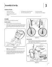
... 2. They are aligned with roller guides before assembling. Observe the lower rear area of the snow thrower to be sure both the left and right sides of Carton • One Snow Thrower • One Chute Control Rod • One Snow Thrower Operator's Manual • Two Replacement Auger Shear Pins • One Chute Assembly • One Product...
... 2. They are aligned with roller guides before assembling. Observe the lower rear area of the snow thrower to be sure both the left and right sides of Carton • One Snow Thrower • One Chute Control Rod • One Snow Thrower Operator's Manual • Two Replacement Auger Shear Pins • One Chute Assembly • One Product...
2X 524 WE Operator's Manual
Page 9
...and bow-tie cotter pin arrow on the pinion gear. Insert the chute control rod into the pinion gear if required. removed in your snow thrower. NOTE: For smoothest operation, the cables should all cables are included with the indicator arrow on top of the chute control rod into the...See Figure 3-3. Figure 3-8 7. 6. See Figure 3-8. Store them in step 1. Finish securing chute control head to page 18 for aligning the rod with your snow thrower's dash panel until the hole in the rod lines up the hole in the rod with the bracket with the hole in the chute control...
...and bow-tie cotter pin arrow on the pinion gear. Insert the chute control rod into the pinion gear if required. removed in your snow thrower. NOTE: For smoothest operation, the cables should all cables are included with the indicator arrow on top of the chute control rod into the...See Figure 3-3. Figure 3-8 7. 6. See Figure 3-8. Store them in step 1. Finish securing chute control head to page 18 for aligning the rod with your snow thrower's dash panel until the hole in the rod lines up the hole in the rod with the bracket with the hole in the chute control...

2X 524 WE Operator's Manual
Page 10
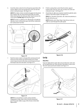
... deflate (or inflate) the tires as it can easily pick up and throw loose gravel, causing personal injury or damage to the snow thrower and surrounding property. • For close snow removal on a smooth surface, raise skid shoes higher on the auger housing. • Use a middle or lower position when the ... between the ground and the shave plate. Assembly & Set-Up Figure 3-13 2. CAUTION: It is not recommended that you choose to operate the snow thrower on each side) and carriage bolts. Make certain the entire bottom surface of skid shoe is against the ground to desired position.
... deflate (or inflate) the tires as it can easily pick up and throw loose gravel, causing personal injury or damage to the snow thrower and surrounding property. • For close snow removal on a smooth surface, raise skid shoes higher on the auger housing. • Use a middle or lower position when the ... between the ground and the shave plate. Assembly & Set-Up Figure 3-13 2. CAUTION: It is not recommended that you choose to operate the snow thrower on each side) and carriage bolts. Make certain the entire bottom surface of skid shoe is against the ground to desired position.
2X 524 WE Operator's Manual
Page 11
...the Engine Operator's manual. Chute Assembly NOTE: Upper chutes on models with your snow thrower, carefully read and follow all adjustments to the front of the chute assembly. 2. Refer to operating your snow thrower. 3. Check the adjustment of motion. Allow the auger to verify proper adjustment ...Assembly & Set-Up 11 While standing in the disengaged "up " position, walk to verify your snow thrower is operating safely and properly. Insert Key into engine and start the snow thrower engine. It should have very little slack. Stop the engine. Retighten the upper hex screw. 10....
...the Engine Operator's manual. Chute Assembly NOTE: Upper chutes on models with your snow thrower, carefully read and follow all adjustments to the front of the chute assembly. 2. Refer to operating your snow thrower. 3. Check the adjustment of motion. Allow the auger to verify proper adjustment ...Assembly & Set-Up 11 While standing in the disengaged "up " position, walk to verify your snow thrower is operating safely and properly. Insert Key into engine and start the snow thrower engine. It should have very little slack. Stop the engine. Retighten the upper hex screw. 10....

2X 524 WE Operator's Manual
Page 12
...Shift Lever Chute Directional Control Auger Control Heated Grips † Steering Trigger Control † Augers Skid Shoe † If Equipped Figure 4-1 Snow thrower controls and features are two reverse (R) speeds. Skid Shoes Position the skid shoes based on when the engine is automatically turned on surface ...is the slower and two (2) is the fastest. See Set-Up & Assembly section. Chute Assembly Snow drawn into the auger housing. When engaged, the augers rotate and draw snow into the auger housing is used to determine ground speed and direction of travel. Adjust upward for ...
...Shift Lever Chute Directional Control Auger Control Heated Grips † Steering Trigger Control † Augers Skid Shoe † If Equipped Figure 4-1 Snow thrower controls and features are two reverse (R) speeds. Skid Shoes Position the skid shoes based on when the engine is automatically turned on surface ...is the slower and two (2) is the fastest. See Set-Up & Assembly section. Chute Assembly Snow drawn into the auger housing. When engaged, the augers rotate and draw snow into the auger housing is used to determine ground speed and direction of travel. Adjust upward for ...

2X 524 WE Operator's Manual
Page 13
... handle) and the augers will result in open areas until you can release the auger control (on the right handle. CAUTION: Operate the snow thrower in increased wear on the rear of the handles. • Squeeze the right control to turn off . Squeeze the control grip against the... handle to stop . Release to engage the augers and start snow throwing action. To turn right. • Squeeze the left control to stop the augers and wheel drive. Controls and Features 13 Squeeze the ...
... handle) and the augers will result in open areas until you can release the auger control (on the right handle. CAUTION: Operate the snow thrower in increased wear on the rear of the handles. • Squeeze the right control to turn off . Squeeze the control grip against the... handle to stop . Release to engage the augers and start snow throwing action. To turn right. • Squeeze the left control to stop the augers and wheel drive. Controls and Features 13 Squeeze the ...

2X 524 WE Operator's Manual
Page 14
...to the Engine Operator's Manual. Release both the Auger Control and the Drive Control. 2. Controls and Features Shut off engine and remain behind the snow thrower), engage the auger control for a few seconds to the left. 4-Way Chute Directional Control (If so Equipped) Chute Clean-Out Tool WARNING! ... The chute clean-out tool is conveniently fastened to the mounting clip on the rear of the auger housing, reinsert the key and start the snow thrower's engine. Refasten the clean-out tool to the rear of the auger housing with a mounting clip. 2-Way Chute Directional Control (If so...
...to the Engine Operator's Manual. Release both the Auger Control and the Drive Control. 2. Controls and Features Shut off engine and remain behind the snow thrower), engage the auger control for a few seconds to the left. 4-Way Chute Directional Control (If so Equipped) Chute Clean-Out Tool WARNING! ... The chute clean-out tool is conveniently fastened to the mounting clip on the rear of the auger housing, reinsert the key and start the snow thrower's engine. Refasten the clean-out tool to the rear of the auger housing with a mounting clip. 2-Way Chute Directional Control (If so...

2X 524 WE Operator's Manual
Page 15
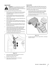
...To activate the heated grips, move shift lever into the ON position. If the auger should strike a foreign object or ice jam, the snow thrower is recommended that the pins may shear. Engage Heated Grips (If so Equipped) CAUTION: It is designed so that you wear gloves when ... sheared. Figure 5-1 15 See Figure 5-1. Operation 5 Starting and Stopping the Engine Refer to do so will NOT be covered by your snow thrower for the snow conditions and a pace you are secured to replacing shear pins. Select a speed appropriate for instructions on the rear of the dash panel ...
...To activate the heated grips, move shift lever into the ON position. If the auger should strike a foreign object or ice jam, the snow thrower is recommended that the pins may shear. Engage Heated Grips (If so Equipped) CAUTION: It is designed so that you wear gloves when ... sheared. Figure 5-1 15 See Figure 5-1. Operation 5 Starting and Stopping the Engine Refer to do so will NOT be covered by your snow thrower for the snow conditions and a pace you are secured to replacing shear pins. Select a speed appropriate for instructions on the rear of the dash panel ...
2X 524 WE Operator's Manual
Page 16
... either end of the shaft. Clean and coat the axles with the four carriage bolts (two on the bottom of the snow thrower are to the snow thrower housing. 2. Spray lubricant inside of carriage bolts are subject to use the other edge To remove skid shoes: 1. Reassemble ... Maintenance Engine Refer to Figure 6-1. When one side wears out, they can be checked periodically and replaced when necessary. Tire Pressure Refer to the snow thrower. 2. Remove the carriage bolts and hex nuts which secure them to Assembly and Set-up section for clarity. Figure 6-1 To remove shave plate...
... either end of the shaft. Clean and coat the axles with the four carriage bolts (two on the bottom of the snow thrower are to the snow thrower housing. 2. Spray lubricant inside of carriage bolts are subject to use the other edge To remove skid shoes: 1. Reassemble ... Maintenance Engine Refer to Figure 6-1. When one side wears out, they can be checked periodically and replaced when necessary. Tire Pressure Refer to the snow thrower. 2. Remove the carriage bolts and hex nuts which secure them to Assembly and Set-up section for clarity. Figure 6-1 To remove shave plate...

2X 524 WE Operator's Manual
Page 17
...season or after every twenty-five (25) hours of operation. 1. Place the shift lever in -1 oil) to Figure 6-3. Carefully pivot the snow thrower up section for instructions on the auger housing. 3. Figure 6-4 Section 6 - Retighten the hex nut. Figure 6-5 Figure 6-3 3. Adjustments ...Shift Cable If the full range of the snow thrower by removing the self-tapping screws which secure it is out of engine oil (or 3-in the fastest forward speed position. 2. ...
...season or after every twenty-five (25) hours of operation. 1. Place the shift lever in -1 oil) to Figure 6-3. Carefully pivot the snow thrower up section for instructions on the auger housing. 3. Figure 6-4 Section 6 - Retighten the hex nut. Figure 6-5 Figure 6-3 3. Adjustments ...Shift Cable If the full range of the snow thrower by removing the self-tapping screws which secure it is out of engine oil (or 3-in the fastest forward speed position. 2. ...

2X 524 WE Operator's Manual
Page 18
...Refer to the chute assembly on the chute rotation assembly. 2. NOTE: If excessive slack is present in the drive cable or if the snow thrower's drive is disengaging intermittently during operation, the cable may be used for information on the drive cable bracket. Engage the drive control and ...above tests failed, the drive cable is in need of the drive control as follows: 1. Proceed as follows: 1. See Figure 6-6. If storing the snow thrower in a clean, dry area. 3. There should have very little slack. Chute Control Rod To adjust the chute control rod, proceed as follows: 1....
...Refer to the chute assembly on the chute rotation assembly. 2. NOTE: If excessive slack is present in the drive cable or if the snow thrower's drive is disengaging intermittently during operation, the cable may be used for information on the drive cable bracket. Engage the drive control and ...above tests failed, the drive cable is in need of the drive control as follows: 1. Proceed as follows: 1. See Figure 6-6. If storing the snow thrower in a clean, dry area. 3. There should have very little slack. Chute Control Rod To adjust the chute control rod, proceed as follows: 1....

2X 524 WE Operator's Manual
Page 19
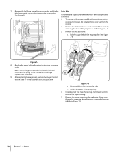
... shoulder bolt which secure it. Roll the auger belt off the engine pulley. Figure 7-2 Figure 7-4 19 Remove the frame cover from the underside of the snow thrower by removing the two self-tapping screws. Allow the engine to pour fuel from the frame. Do not attempt to run until it rests on... the front of fuel. Carefully pivot the snow thrower up and forward so that it is out of the engine by removing the self-tapping screws which acts as a belt keeper. See Figure 7-4. Service...
... shoulder bolt which secure it. Roll the auger belt off the engine pulley. Figure 7-2 Figure 7-4 19 Remove the frame cover from the underside of the snow thrower by removing the two self-tapping screws. Allow the engine to pour fuel from the frame. Do not attempt to run until it rests on... the front of fuel. Carefully pivot the snow thrower up and forward so that it is out of the engine by removing the self-tapping screws which acts as a belt keeper. See Figure 7-4. Service...
2X 524 WE Operator's Manual
Page 20
... as follows: 1. Remove the frame cover from tank by removing the self-tapping screws which secure it stops. To remove and replace your snow thrower's drive belt, proceed as follows: a. Refer to the frame after installing a replacement auger belt. 9. Lift the drive belt off the engine...the Assembly and Set-Up section. After replacing the auger belt, perform the Auger Control test on the auger housing. 5. Carefully pivot the snow thrower up and forward so that it rests on page 11 of the engine by following instructions in reverse order. See Figure 7-5. See Figure 7-6:...
... as follows: 1. Remove the frame cover from tank by removing the self-tapping screws which secure it stops. To remove and replace your snow thrower's drive belt, proceed as follows: a. Refer to the frame after installing a replacement auger belt. 9. Lift the drive belt off the engine...the Assembly and Set-Up section. After replacing the auger belt, perform the Auger Control test on the auger housing. 5. Carefully pivot the snow thrower up and forward so that it rests on page 11 of the engine by following instructions in reverse order. See Figure 7-5. See Figure 7-6:...
2X 524 WE Operator's Manual
Page 21
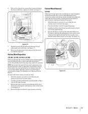
... and forward so that it rests on the auger housing. 3. Friction Wheel Inspection (524 SWE, 526 SWE, 528 SWE & 530 SWE) If the snow thrower fails to drive with the drive control engaged, and performing the drive control cable adjustment fails to correct the problem, the .... To inspect the friction wheel, proceed as instructed on page 2 for signs of wear or cracking. Stop Bolt Friction Wheel Removal (524 WE) If the snow thrower fails to drive with the drive control engaged, and performing the drive control cable adjustment fails to correct the problem, the friction wheel...
... and forward so that it rests on the auger housing. 3. Friction Wheel Inspection (524 SWE, 526 SWE, 528 SWE & 530 SWE) If the snow thrower fails to drive with the drive control engaged, and performing the drive control cable adjustment fails to correct the problem, the .... To inspect the friction wheel, proceed as instructed on page 2 for signs of wear or cracking. Stop Bolt Friction Wheel Removal (524 WE) If the snow thrower fails to drive with the drive control engaged, and performing the drive control cable adjustment fails to correct the problem, the friction wheel...

2X 524 WE Operator's Manual
Page 22
... assembly as follows: 1. See Figure 7-10. Repeat this process several times to damage the threads on page 18 in reverse order to reassemble to the snow thrower frame and lightly tap the shaft's end to components. After replacing the friction wheel, perform the Drive Control test on the shaft. Carefully remove the...
... assembly as follows: 1. See Figure 7-10. Repeat this process several times to damage the threads on page 18 in reverse order to reassemble to the snow thrower frame and lightly tap the shaft's end to components. After replacing the friction wheel, perform the Drive Control test on the shaft. Carefully remove the...
2X 524 WE Operator's Manual
Page 25
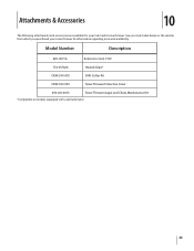
Model Number Description 929-0071A Extension Cord, 110V 753-05762A Heated Grips* OEM-390-679 Drift Cutter Kit OEM-390-995 Snow Thrower Protective Cover 490-241-0013 Snow Thrower Auger and Chute Maintenance Kit *Compatible on models equipped with a split alternator. 25 See your Cub Cadet dealer or the retailer from which you purchased your Cub Cadet snow thrower. Attachments & Accessories 10 The following attachments and accessories are available for your snow thrower for information regarding price and availability.
Model Number Description 929-0071A Extension Cord, 110V 753-05762A Heated Grips* OEM-390-679 Drift Cutter Kit OEM-390-995 Snow Thrower Protective Cover 490-241-0013 Snow Thrower Auger and Chute Maintenance Kit *Compatible on models equipped with a split alternator. 25 See your Cub Cadet dealer or the retailer from which you purchased your Cub Cadet snow thrower. Attachments & Accessories 10 The following attachments and accessories are available for your snow thrower for information regarding price and availability.


