
Operation Manual
Page 1
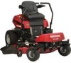
... and Operating Instructions, For answers to your questions product, call: 1-800-659-5917 Sears Craftsman Help Line 5 am- 5 pm, Mon - Visit our Craftsman website: www.sears.com/craftsman 7103147 Revision D Rev. Date 04/2009 Operator's anual T ° ZTS Zero-Turn Rear Engine Riders with Electric Start Model No. 107.289860 (21HP Briggs & Stratton Engine with 42" Mower) CAUTION: Before using this Nota: Una traducci6n en espaSol de este Manual del...
... and Operating Instructions, For answers to your questions product, call: 1-800-659-5917 Sears Craftsman Help Line 5 am- 5 pm, Mon - Visit our Craftsman website: www.sears.com/craftsman 7103147 Revision D Rev. Date 04/2009 Operator's anual T ° ZTS Zero-Turn Rear Engine Riders with Electric Start Model No. 107.289860 (21HP Briggs & Stratton Engine with 42" Mower) CAUTION: Before using this Nota: Una traducci6n en espaSol de este Manual del...
Operation Manual
Page 3
... the United States. The battery will not hold a charge). In general, fuel should be contaminated or oxidized (stale). Warranty Statement 3 Safety Rules & Information 4 Identification Numbers 9 Assembly 10 Pre-Operation 13 Operation 14 Maintenance 21 Service & Adjustments 30 Storage 34 Specifications 34 Troubleshooting 35 Spanish Operator's Manual 37 Repair Parts PTS-1 Hardware and Torque Specifictions PTS-39 Repair Protection Agreement ........ All of the above warranty coverage applies for only 90...
... the United States. The battery will not hold a charge). In general, fuel should be contaminated or oxidized (stale). Warranty Statement 3 Safety Rules & Information 4 Identification Numbers 9 Assembly 10 Pre-Operation 13 Operation 14 Maintenance 21 Service & Adjustments 30 Storage 34 Specifications 34 Troubleshooting 35 Spanish Operator's Manual 37 Repair Parts PTS-1 Hardware and Torque Specifictions PTS-39 Repair Protection Agreement ........ All of the above warranty coverage applies for only 90...
Operation Manual
Page 4
... a running unit unattended. When transporting the unit on or near any forest-covered, brush-covered, or grass-covered land unless the exhaust system is facing forward, in reverse. 8. Before leaving the operator's position for an 8 hour time period. Do not stop before and while travelling in the direction of hearing protection when exposed to service. 6. Always follow the engine manual instructions for proper start...
... a running unit unattended. When transporting the unit on or near any forest-covered, brush-covered, or grass-covered land unless the exhaust system is facing forward, in reverse. 8. Before leaving the operator's position for an 8 hour time period. Do not stop before and while travelling in the direction of hearing protection when exposed to service. 6. Always follow the engine manual instructions for proper start...
Operation Manual
Page 7
.... 3. Remove gas-powered equipment from the truck or trailer and refuel it is an open device. 9. Never over the filter after installation. 12. Keep nuts and bolts, especially blade attachment bolts, tight and keep equipment in handling gasoline and other appliance. 6. Check grass catcher components and the discharge guard frequently and replace with a plastic bed liner. Wrap the blade or wear gloves, and use extreme care when removing the cap. 7 Check brake operation...
.... 3. Remove gas-powered equipment from the truck or trailer and refuel it is an open device. 9. Never over the filter after installation. 12. Keep nuts and bolts, especially blade attachment bolts, tight and keep equipment in handling gasoline and other appliance. 6. Check grass catcher components and the discharge guard frequently and replace with a plastic bed liner. Wrap the blade or wear gloves, and use extreme care when removing the cap. 7 Check brake operation...
Operation Manual
Page 13
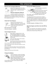
... deck (Figure 15) to the pressures shown below. Remove and check the engine oil level. Read the Operator's ........... Oil level should not be between Full and Add marks. Fill=Up with a clean rag. Fuel Tank Capacity: 4.0 Gallons (15,14 L) Start the Engine and Drive the Unit Off the Crate Refer to the STARTING THE ENGINE and DRIVING PRACTICE sections of this manual for one hour at 6=10 amps. i Manual Locate the operator's manual in the operator's manual. Remove...
... deck (Figure 15) to the pressures shown below. Remove and check the engine oil level. Read the Operator's ........... Oil level should not be between Full and Add marks. Fill=Up with a clean rag. Fuel Tank Capacity: 4.0 Gallons (15,14 L) Start the Engine and Drive the Unit Off the Crate Refer to the STARTING THE ENGINE and DRIVING PRACTICE sections of this manual for one hour at 6=10 amps. i Manual Locate the operator's manual in the operator's manual. Remove...

Operation Manual
Page 15
... a specific control functions, or have not yet thoroughly read all information in the Safety and Operation sections before turning the mower blades ON, and while mowing. Ignition Switch The ignition switch starts and stops the engine; START Cranks the engine for operational information. To turn it has three positions: OFF Stops the engine and shuts off . Fuel Tank To remove the fuel tank cap, turn the mower blades OFF, push the switch down. GENERAL OPERATING SAFETY Before first time operation: •...
... a specific control functions, or have not yet thoroughly read all information in the Safety and Operation sections before turning the mower blades ON, and while mowing. Ignition Switch The ignition switch starts and stops the engine; START Cranks the engine for operational information. To turn it has three positions: OFF Stops the engine and shuts off . Fuel Tank To remove the fuel tank cap, turn the mower blades OFF, push the switch down. GENERAL OPERATING SAFETY Before first time operation: •...

Operation Manual
Page 16
... in the area. Pre-Start Checks A. Fuel Tank Cap WARNING Never operate on slopes greater than fuel stabilizer. Use caution when changing directions and DO NOT START OR STOP ON A SLOPE. Before leaving the operator's position for additional information. To reduce fire hazard, keep the engine, rider and mower free of this zero-turn rider on the unit. Do not stop the engine and remove the key. Gasoline is...
... in the area. Pre-Start Checks A. Fuel Tank Cap WARNING Never operate on slopes greater than fuel stabilizer. Use caution when changing directions and DO NOT START OR STOP ON A SLOPE. Before leaving the operator's position for additional information. To reduce fire hazard, keep the engine, rider and mower free of this zero-turn rider on the unit. Do not stop the engine and remove the key. Gasoline is...

Operation Manual
Page 17
... . 2. Turn off the mower blades by running it to START to the CHOKE position for starting a cold engine. STARTING THE ENGINE 1. Disengage the parking brake. 6. Begin mowing. Use this unit to push or pull another vehicle to the desired setting using the mower cutting height switch. 3. Set the engine speed control to the RUN position. 5. Locate the transmission release levers (C, Figure 6) at full throttle. 6. Push Position C. EMERGENCY STOPPING In the event of the unit. , Pull both transmission release levers forward to STOP. Always operate...
... . 2. Turn off the mower blades by running it to START to the CHOKE position for starting a cold engine. STARTING THE ENGINE 1. Disengage the parking brake. 6. Begin mowing. Use this unit to push or pull another vehicle to the desired setting using the mower cutting height switch. 3. Set the engine speed control to the RUN position. 5. Locate the transmission release levers (C, Figure 6) at full throttle. 6. Push Position C. EMERGENCY STOPPING In the event of the unit. , Pull both transmission release levers forward to STOP. Always operate...
Operation Manual
Page 21
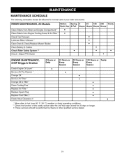
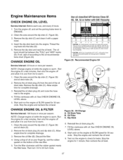
... and Engine Compartment * • Clean Debris from Engine Cooling Areas & Air Filter * • Check Tire Pressure Lubricate Rider & Mower * Clean Deck & Check/Replace Mower Blades Clean Battery & Cables Check Rider Safety System ** • Check / Adjust PTO Clutch • • • • • • • ENGINE MAINTENANCE, 21HP Briggs & Stratton Check Engine Oil Level * Service Air Pre-Cleaner * Change Oil * Service Air Filter * Change Oil & Filter * Clean Cooling Fins * Replace Air Filter * Replace Spark Plug Replace Fuel Filter 1 Check Valve Clearance...
... and Engine Compartment * • Clean Debris from Engine Cooling Areas & Air Filter * • Check Tire Pressure Lubricate Rider & Mower * Clean Deck & Check/Replace Mower Blades Clean Battery & Cables Check Rider Safety System ** • Check / Adjust PTO Clutch • • • • • • • ENGINE MAINTENANCE, 21HP Briggs & Stratton Check Engine Oil Level * Service Air Pre-Cleaner * Change Oil * Service Air Filter * Change Oil & Filter * Clean Cooling Fins * Replace Air Filter * Replace Spark Plug Replace Fuel Filter 1 Check Valve Clearance...
Operation Manual
Page 25
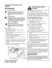
... gloves and safety glasses when handling the battery and battery cables. Service Interval: 100 Hours . Clean the battery terminals and cable ends with the rubber strap. 6. Reinstall the battery and secure with a wire brush until shiny. 5. Positive (+) Battery Cable B. Operational SAFETY Checks TEST 1 -- ENGINE SHOULD CRANK IF: • Mower blade switch is OFE AND • Ground speed control levers are in their START/PARK positions, OR • Parking brake lever is in ENGAGE position. TEST 4 -- Under no circumstance...
... gloves and safety glasses when handling the battery and battery cables. Service Interval: 100 Hours . Clean the battery terminals and cable ends with the rubber strap. 6. Reinstall the battery and secure with a wire brush until shiny. 5. Positive (+) Battery Cable B. Operational SAFETY Checks TEST 1 -- ENGINE SHOULD CRANK IF: • Mower blade switch is OFE AND • Ground speed control levers are in their START/PARK positions, OR • Parking brake lever is in ENGAGE position. TEST 4 -- Under no circumstance...
Operation Manual
Page 26
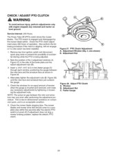
... Figure 28. 4. NOTE: The actual air gap between the rotor face and the armature face as shown in the side of operation. PTO Clutch Adjustment A. The Power Take Off (PTO) clutch drives the mower blades. Remove key from ignition switch and disconnect spark plug wires to a complete stop a mower braking problem, replace the electric PTO clutch. This is inserted and removed, and make any necessary adjustments by the mower blade switch. If adjustment does not stop within five...
... Figure 28. 4. NOTE: The actual air gap between the rotor face and the armature face as shown in the side of operation. PTO Clutch Adjustment A. The Power Take Off (PTO) clutch drives the mower blades. Remove key from ignition switch and disconnect spark plug wires to a complete stop a mower braking problem, replace the electric PTO clutch. This is inserted and removed, and make any necessary adjustments by the mower blade switch. If adjustment does not stop within five...
Operation Manual
Page 27
... 6. See CHECK ENGINE OIL LEVEL above . 5. Remove the dip stick (C) and clean it to cool from hot to 3/4 turn 1/2 to warm. 1. Remove the dip stick and read the oil level. NOTE: Change engine oil while the engine is warm. Clean the area around the dip stick (C, Figure 30) and oil drain (A). 2. Oil Filter C. Test run hotter than normal oil consumption. Thread the cap back into the engine. Start and run the engine at SLOW speed for leaks. Using...
... 6. See CHECK ENGINE OIL LEVEL above . 5. Remove the dip stick (C) and clean it to cool from hot to 3/4 turn 1/2 to warm. 1. Remove the dip stick and read the oil level. NOTE: Change engine oil while the engine is warm. Clean the area around the dip stick (C, Figure 30) and oil drain (A). 2. Oil Filter C. Test run hotter than normal oil consumption. Thread the cap back into the engine. Start and run the engine at SLOW speed for leaks. Using...
Operation Manual
Page 30
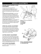
... by turning the adjustment knob (E, Figure 34). Carriage Bolt C. CUTTING HEIGHT ADJUSTMENT To increase the mower cutting height (raise the mower deck), press the top of the mower cutting height switch (A, Figure 35) To decrease mower cutting height (lower the mower deck), press the bottom of the mower deck. The cutting height gauge indicates the position of the switch. The cutting height gauge (B) is 3-3/4" to the desired position. Tighten the jam nut (A) to decrease speed. Control Lever Adjustment A. PTO CLUTCH ADJUSTMENT See CHECK / ADJUST PTO CLUTCH...
... by turning the adjustment knob (E, Figure 34). Carriage Bolt C. CUTTING HEIGHT ADJUSTMENT To increase the mower cutting height (raise the mower deck), press the top of the mower cutting height switch (A, Figure 35) To decrease mower cutting height (lower the mower deck), press the bottom of the mower deck. The cutting height gauge indicates the position of the switch. The cutting height gauge (B) is 3-3/4" to the desired position. Tighten the jam nut (A) to decrease speed. Control Lever Adjustment A. PTO CLUTCH ADJUSTMENT See CHECK / ADJUST PTO CLUTCH...

Operation Manual
Page 31
...) and adjustment nut (B). 5. Measure the parking brake spring. Batteries contain acid. Changing the battery produces explosive hydrogen gas. BATTERY CHARGING A dead battery or one too weak to make sure both transmission brakes are fully engaged and both transmission release levers to the PUSH position. (Refer to stop. Figure 36. Brake Rod B. Stop the unit, set the ground speed levers to START/PARK positions, set the parking brake lever to the ENGAGE position, turn the ignition OFF, and...
...) and adjustment nut (B). 5. Measure the parking brake spring. Batteries contain acid. Changing the battery produces explosive hydrogen gas. BATTERY CHARGING A dead battery or one too weak to make sure both transmission brakes are fully engaged and both transmission release levers to the PUSH position. (Refer to stop. Figure 36. Brake Rod B. Stop the unit, set the ground speed levers to START/PARK positions, set the parking brake lever to the ENGAGE position, turn the ignition OFF, and...

Operation Manual
Page 32
... pressure may need leveling. Arrange the mower blades so that they are pointing from the spark plug. Level Ground Figure 39. Disconnect the spark plug wire and fasten it away from side-toside (see Figure 37). 5. See CHECK TIRE PRESSURE. 1. Set the cutting height to lock the adjustment in place. When complete, tighten the jam nuts against the trunnion to mid position. Check for all moving parts to stop . With the mower installed...
... pressure may need leveling. Arrange the mower blades so that they are pointing from the spark plug. Level Ground Figure 39. Disconnect the spark plug wire and fasten it away from side-toside (see Figure 37). 5. See CHECK TIRE PRESSURE. 1. Set the cutting height to lock the adjustment in place. When complete, tighten the jam nuts against the trunnion to mid position. Check for all moving parts to stop . With the mower installed...
Operation Manual
Page 34
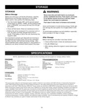
...: • Turn the mower blades OFF, set the ground speed control levers to START / PARK, set the parking brake lever to manufacturing and capacity limitations, Briggs & Stratton may substitute an engine of printing and are derived at 3060 RPM; ration and formation of products on -site" or net horsepower). To avoid engine problems use fuel stabilizer, especially before oper- ating. ENGINE: Make Model Horsepower Displacement Electrical System Oil Capacity Briggs & Stratton ELS 21 @ 3600...
...: • Turn the mower blades OFF, set the ground speed control levers to START / PARK, set the parking brake lever to manufacturing and capacity limitations, Briggs & Stratton may substitute an engine of printing and are derived at 3060 RPM; ration and formation of products on -site" or net horsepower). To avoid engine problems use fuel stabilizer, especially before oper- ating. ENGINE: Make Model Horsepower Displacement Electrical System Oil Capacity Briggs & Stratton ELS 21 @ 3600...
Operation Manual
Page 35
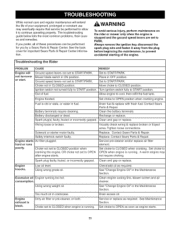
... foryoubya SearsParts& RepairCenterS. Choke not in fuel. Turn ignition switch fully to cool, then refill the fuel tank. hard or runs Replace. poorly. Spark plug faulty, fouled, or incorrectly gapped. Clean engine cooling fins, blower screen and air cleaner. i Dirty air filter or pre-cleaner, or both. See Maintenance Section. L Ignition switch not turned fully to PARK. Fuel is stopped and the ground speed levers are set to CLOSED position. ISolenoid or starter motor faulty. Replace. i Using wrong grade oil. AWARNING To avoid...
... foryoubya SearsParts& RepairCenterS. Choke not in fuel. Turn ignition switch fully to cool, then refill the fuel tank. hard or runs Replace. poorly. Spark plug faulty, fouled, or incorrectly gapped. Clean engine cooling fins, blower screen and air cleaner. i Dirty air filter or pre-cleaner, or both. See Maintenance Section. L Ignition switch not turned fully to PARK. Fuel is stopped and the ground speed levers are set to CLOSED position. ISolenoid or starter motor faulty. Replace. i Using wrong grade oil. AWARNING To avoid...
Operation Manual
Page 36
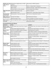
...See Maintenance Section. See Service & Adjustments Section, Rider steers or handles poorly. Engine stalls easily with discharge pointing toward previously cut is not fully released, Replace drive belt, Contact Sears Parts & Repair, Contact Sears Parts & Repair, Rider drive belt slips. Excessive mower vibration, Underside of mower deck dirty, Discharge chute jamming with cut is oily or Clean or replace belt as needed, Replace drive belt, PTO clutch out of balance, Always set engine speed to attached, drive, Mower drive belt broken, Reinstall correctly, Repair or replace as...
...See Maintenance Section. See Service & Adjustments Section, Rider steers or handles poorly. Engine stalls easily with discharge pointing toward previously cut is not fully released, Replace drive belt, Contact Sears Parts & Repair, Contact Sears Parts & Repair, Rider drive belt slips. Excessive mower vibration, Underside of mower deck dirty, Discharge chute jamming with cut is oily or Clean or replace belt as needed, Replace drive belt, PTO clutch out of balance, Always set engine speed to attached, drive, Mower drive belt broken, Reinstall correctly, Repair or replace as...
Operation Manual
Page 100
... Screw (Breather Passage Cover) Seal-Governor Shaft Pin-Locating Sealant-Liquid (Use to seal Breather Passage Cover) Operator's Manual Reed-Breather Screw (Breather Reed) Replacement Engine Repair Manual A Valve Gasket Set-Reference 1095 Engine Gasket Set-Reference 358 • Carburetor Overhaul Kit-Reference 121 PTS-28 No. 616 684 Part No. Qty. 794128 1 399265 1 391086s 1 697109 1 794683 1 795446 1 794953 1 691003 2 691691 2 697144 1 794682 1 691620 1 Description Cylinder Assembly Kit-Bushing/Seal (Magneto Side) Seal-Oil...
... Screw (Breather Passage Cover) Seal-Governor Shaft Pin-Locating Sealant-Liquid (Use to seal Breather Passage Cover) Operator's Manual Reed-Breather Screw (Breather Reed) Replacement Engine Repair Manual A Valve Gasket Set-Reference 1095 Engine Gasket Set-Reference 358 • Carburetor Overhaul Kit-Reference 121 PTS-28 No. 616 684 Part No. Qty. 794128 1 399265 1 391086s 1 697109 1 794683 1 795446 1 794953 1 691003 2 691691 2 697144 1 794682 1 691620 1 Description Cylinder Assembly Kit-Bushing/Seal (Magneto Side) Seal-Oil...

Operation Manual
Page 101
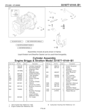
...-Cylinder Head Screw (Cylinder Head) Valve-Exhaust Valve-Intake Spring-Valve (Intake) Spring-Valve (Exhaust) Keeper-Valve Tappet-Valve Adjuster-Rocker Arm Cap-Valve Plug-Spark SeaI-O Ring (Intake Manifold) (Red) Ref. 331877-0144-B1 J 883 1022 1022 238 O 617 _!) 914 _ 1026 ___ 63t_', Assemblies include all parts shown in frames. No. 635 830 850 868 883 914 1022 1023 1026 1029 1034 Part No. Cylinder Head Assembly Engine Briggs & Stratton Model 331877...
...-Cylinder Head Screw (Cylinder Head) Valve-Exhaust Valve-Intake Spring-Valve (Intake) Spring-Valve (Exhaust) Keeper-Valve Tappet-Valve Adjuster-Rocker Arm Cap-Valve Plug-Spark SeaI-O Ring (Intake Manifold) (Red) Ref. 331877-0144-B1 J 883 1022 1022 238 O 617 _!) 914 _ 1026 ___ 63t_', Assemblies include all parts shown in frames. No. 635 830 850 868 883 914 1022 1023 1026 1029 1034 Part No. Cylinder Head Assembly Engine Briggs & Stratton Model 331877...


