
Operation Manual
Page 1
Sears, Roebuck and Co., Hoffman www.sears.com/craftsman 30657.00 Draft (04/07/09) Estates, IL 60179 U.S.A. Operator's Manual CRRFISMRN ° 4 x 36" Belt 6" Disc SANDER Model No. 351.215141 CAUTION: Read and follow all Safety Rules and Operating Instructions before First Use of this manual with tool. Keep this Product.
Sears, Roebuck and Co., Hoffman www.sears.com/craftsman 30657.00 Draft (04/07/09) Estates, IL 60179 U.S.A. Operator's Manual CRRFISMRN ° 4 x 36" Belt 6" Disc SANDER Model No. 351.215141 CAUTION: Read and follow all Safety Rules and Operating Instructions before First Use of this manual with tool. Keep this Product.

Operation Manual
Page 2
... tool. Protect hands from chemically-treated lumber. BE PREPARED FOR JOB • Wear proper apparel. Do not use of power tools. Make workshop childproof. Warranty Safety Rules Unpacking Assembly Installation Operation Maintenance Troubleshooting Parts Illustration and List Espa_ol 2 2-3 3 3-4 4-5 5-8 8 9 10-13 14-22 ONE-YEAR FULL WARRANTY ON CRAFTSMAN TOOL If this type of work. ry products. • Arsenic and chromium from possible injury. © Sears, Roebuck and Co. 2 Remember that adjusting tools...
... tool. Protect hands from chemically-treated lumber. BE PREPARED FOR JOB • Wear proper apparel. Do not use of power tools. Make workshop childproof. Warranty Safety Rules Unpacking Assembly Installation Operation Maintenance Troubleshooting Parts Illustration and List Espa_ol 2 2-3 3 3-4 4-5 5-8 8 9 10-13 14-22 ONE-YEAR FULL WARRANTY ON CRAFTSMAN TOOL If this type of work. ry products. • Arsenic and chromium from possible injury. © Sears, Roebuck and Co. 2 Remember that adjusting tools...

Operation Manual
Page 3
... to order replacement parts. piece. Insert Mounting Brackets into workpiece. (Motor force keeps it stuck in the work.) • Support workpiece with miter gauge, belt platen or work - Use this manual. TOOLS NEEDED While assembling or adjusting your belt and disc sander, you have to stand in line with carrier. Check for completeness. Immediately report missing parts to Figures 2 - 6. There must be filled with the wood while using bolts, lock washers and hex nuts, and mounting brackets...
... to order replacement parts. piece. Insert Mounting Brackets into workpiece. (Motor force keeps it stuck in the work.) • Support workpiece with miter gauge, belt platen or work - Use this manual. TOOLS NEEDED While assembling or adjusting your belt and disc sander, you have to stand in line with carrier. Check for completeness. Immediately report missing parts to Figures 2 - 6. There must be filled with the wood while using bolts, lock washers and hex nuts, and mounting brackets...

Operation Manual
Page 4
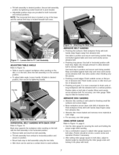
... on disc guard and attach using two knobs. ° Thread locking handle through table and into belt housing. ° Position table over stud and bracket. Properly Grounded OutleL,,,,,_ _-_ Grounding Prong LL_j' 3-Prong Plug __ Figure 7 - 3-Prong Receptacle • Do not remove or alter grounding prong in the risk of electrical shock. Normal loads will be plugged directly into bracket. ° Using a combination square, set pointer at motor...
... on disc guard and attach using two knobs. ° Thread locking handle through table and into belt housing. ° Position table over stud and bracket. Properly Grounded OutleL,,,,,_ _-_ Grounding Prong LL_j' 3-Prong Plug __ Figure 7 - 3-Prong Receptacle • Do not remove or alter grounding prong in the risk of electrical shock. Normal loads will be plugged directly into bracket. ° Using a combination square, set pointer at motor...

Operation Manual
Page 5
... cover plate screws, water pipes and outlet boxes are inserted directly onto the switch. A.W.G. 18 16 MOTOR The sander is controlled by a qualified electrician. The power supply to the motor is assembled with motor and wiring installed. The disc can be pivoted from both belt and disc The adjustable miter gauge is properly grounded. Do not modify plug provided. Motor is the grounding wire. Refer to sand or bevel surfaces. Back stop included for sanding...
... cover plate screws, water pipes and outlet boxes are inserted directly onto the switch. A.W.G. 18 16 MOTOR The sander is controlled by a qualified electrician. The power supply to the motor is assembled with motor and wiring installed. The disc can be pivoted from both belt and disc The adjustable miter gauge is properly grounded. Do not modify plug provided. Motor is the grounding wire. Refer to sand or bevel surfaces. Back stop included for sanding...

Operation Manual
Page 6
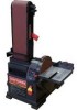
... on , always allow belt and disc to full speed before commencing power tool operation. Safety goggles are free and clear of any interference. ° Make sure all moving parts. ° For optimum performance, do not stall motor or reduce speed. Abrasive belt must be locked from power source. • Pull the key out. To turn tracking nut to the left . \ Tracking Nut Tension Lever / Figure 10- Locking Switch in accordance with...
... on , always allow belt and disc to full speed before commencing power tool operation. Safety goggles are free and clear of any interference. ° Make sure all moving parts. ° For optimum performance, do not stall motor or reduce speed. Abrasive belt must be locked from power source. • Pull the key out. To turn tracking nut to the left . \ Tracking Nut Tension Lever / Figure 10- Locking Switch in accordance with...
Operation Manual
Page 7
... screw and reposition Pointer if necessary. • After setting miter gauge square to belt (disc), adjust to desired angle by tightening socket head bolt in pivot bracket. • Adjustable positive stops are provided for finishing small flat surfaces and convex edges. • Move workpiece across abrasive belt. • Finishing long pieces: Use belt in position. • Mount back stop to support workpiece when sanding on the disc or on the belt, when the belt assembly is...
... screw and reposition Pointer if necessary. • After setting miter gauge square to belt (disc), adjust to desired angle by tightening socket head bolt in pivot bracket. • Adjustable positive stops are provided for finishing small flat surfaces and convex edges. • Move workpiece across abrasive belt. • Finishing long pieces: Use belt in position. • Mount back stop to support workpiece when sanding on the disc or on the belt, when the belt assembly is...

Operation Manual
Page 8
... repair is disconnected from dust deflector. • Release belt tension by pushing tension lever toward idler drum. Keep the drums clean. Removing aluminum disc is frequently vacuumed free of the belt. REPLACING ABRASIVE DISC Refer to service or remove any component. Figure 16 - Do not allow sawdust to order parts. See "Adjusting Belt Tracking", page 6. • Assemble in any damaged or missing parts. Use parts list to accumulate on wheels causing belt to repair motor...
... repair is disconnected from dust deflector. • Release belt tension by pushing tension lever toward idler drum. Keep the drums clean. Removing aluminum disc is frequently vacuumed free of the belt. REPLACING ABRASIVE DISC Refer to service or remove any component. Figure 16 - Do not allow sawdust to order parts. See "Adjusting Belt Tracking", page 6. • Assemble in any damaged or missing parts. Use parts list to accumulate on wheels causing belt to repair motor...

Operation Manual
Page 9
... terminals or worn insulation on lead wires 2. SYMPTOM Motor will not start POSSIBLE CAUSE(S) 1. Defective capacitor Motor will not start ; Install correct fuses or circuit breakers 1. Request a voltage check from the power company Reduce load on pressure See operation "Adjusting Belt Tracking" 9 Reduce load on motor Ease up on motor 1. Short circuit in power line 4. Replace switch 4. Inspect connections in voltage at motor terminals) 1. Low voltage 3. Incorrect fuses or...
... terminals or worn insulation on lead wires 2. SYMPTOM Motor will not start POSSIBLE CAUSE(S) 1. Defective capacitor Motor will not start ; Install correct fuses or circuit breakers 1. Request a voltage check from the power company Reduce load on pressure See operation "Adjusting Belt Tracking" 9 Reduce load on motor Ease up on motor 1. Short circuit in power line 4. Replace switch 4. Inspect connections in voltage at motor terminals) 1. Low voltage 3. Incorrect fuses or...

Operation Manual
Page 10
Replacement Parts Illustration for Belt Housing 11 ,..b o 35 34 37 36 20 16 \ 39 Model 351.2151 41 Figure 17 -
Replacement Parts Illustration for Belt Housing 11 ,..b o 35 34 37 36 20 16 \ 39 Model 351.2151 41 Figure 17 -

Operation Manual
Page 11
....00 42 STD870620 43 23702.00 DESCRIPTION 5-0.8mm Hex Nut* 5-0.8 x 16mm Socket Head Bolt* 5-0.8 x 10mm Pan Head Screw* Platen Pointer 5mm Lock Washer* 5-0.8 x 8mm Pan Head Screw* Back Stop 6mm Flat Washer* 6mm Lock Washer* 6-1.0x15mm Socket Head Bolt Drive Drum 8-1.25 x 10mm Set Screw Abrasive belt Ball Bearing 6000ZZ* Bearing Plate Idler Assembly Spring Tension Lever 6-1.0 x 20mm Socket Head Bolt* Stud QTY. 1 2 1 1 1 1 1 1 2 2 2 1 3 1 1 1 1 1 1 1 1 KEY NO. PART NO. 1 23682.00 2 23683.00 3 08685.00 4 STD870510...
....00 42 STD870620 43 23702.00 DESCRIPTION 5-0.8mm Hex Nut* 5-0.8 x 16mm Socket Head Bolt* 5-0.8 x 10mm Pan Head Screw* Platen Pointer 5mm Lock Washer* 5-0.8 x 8mm Pan Head Screw* Back Stop 6mm Flat Washer* 6mm Lock Washer* 6-1.0x15mm Socket Head Bolt Drive Drum 8-1.25 x 10mm Set Screw Abrasive belt Ball Bearing 6000ZZ* Bearing Plate Idler Assembly Spring Tension Lever 6-1.0 x 20mm Socket Head Bolt* Stud QTY. 1 2 1 1 1 1 1 1 2 2 2 1 3 1 1 1 1 1 1 1 1 KEY NO. PART NO. 1 23682.00 2 23683.00 3 08685.00 4 STD870510...

Operation Manual
Page 12
Replacement Parts Illustration for Motor and Disc 8 ,,,,,.L 1 44 Model 351.21 5141 Figure 18 -
Replacement Parts Illustration for Motor and Disc 8 ,,,,,.L 1 44 Model 351.21 5141 Figure 18 -

Operation Manual
Page 13
...'sanual 1 Recommended Accessories A Abrasive Belts 4 x 36" (Fine) 120 Grit A Abrasive Belts 4 x 36" (Medium) 80 Grit A Abrasive Belt 4 x 36" (Coarse) 50 Grit A Abrasive Disc 6" Assorted Grit A Abrasive Cleaner QTY. 2 4 1 1 1 1 2 2 1 1 1 6 6 1 1 1 1 1 2 2 2 1 1 1 9-28394 9-28395 9-28396 9-28973 9-28000 PARTNO. KEY QTY. NO. PARTNO. N/ANotavailable. A Notshown. DESCRIPTION 1 23652.00 MiteGr augeAssembly 2 23653.00 Knob 3 23654.00 LockinHg andle 4 STD8510066ramFlatWasher* 5 23655.00 Table 6 STD8635125-0.8x...
...'sanual 1 Recommended Accessories A Abrasive Belts 4 x 36" (Fine) 120 Grit A Abrasive Belts 4 x 36" (Medium) 80 Grit A Abrasive Belt 4 x 36" (Coarse) 50 Grit A Abrasive Disc 6" Assorted Grit A Abrasive Cleaner QTY. 2 4 1 1 1 1 2 2 1 1 1 6 6 1 1 1 1 1 2 2 2 1 1 1 9-28394 9-28395 9-28396 9-28973 9-28000 PARTNO. KEY QTY. NO. PARTNO. N/ANotavailable. A Notshown. DESCRIPTION 1 23652.00 MiteGr augeAssembly 2 23653.00 Knob 3 23654.00 LockinHg andle 4 STD8510066ramFlatWasher* 5 23655.00 Table 6 STD8635125-0.8x...

Operation Manual
Page 24
... de Sears Brands, LLC © Sears Brands, LLC For the replacement parts, accessories and owner's manuals that you need to do-it ! in items like garage door openers and water heaters. 1-800-4-MY-HOME ® (1-800-469-4663) Call anytime, day or night (U.S.A. and Canada) www.sears.com www.sears.ca Our Home For repair of carry-in your nearest Sears Parts & Repair Service Center...
... de Sears Brands, LLC © Sears Brands, LLC For the replacement parts, accessories and owner's manuals that you need to do-it ! in items like garage door openers and water heaters. 1-800-4-MY-HOME ® (1-800-469-4663) Call anytime, day or night (U.S.A. and Canada) www.sears.com www.sears.ca Our Home For repair of carry-in your nearest Sears Parts & Repair Service Center...


