

Operation Manual
Page 1
Sears, Roebuck and Co., Hoffman Estates, IL 60179 U.S.A. www.sears.com/craftsman 25759.00 Draft (01/22/08) PARTS LIST ESPAÑOL Keep this Product. SAFETY ASSEMBLY OPERATION MAINTENANCE Operator's Manual Oscillating Spindle SANDER Model No. 351.215000 CAUTION: Read and follow all Safety Rules and Operating Instructions before First Use of this manual with tool.
Sears, Roebuck and Co., Hoffman Estates, IL 60179 U.S.A. www.sears.com/craftsman 25759.00 Draft (01/22/08) PARTS LIST ESPAÑOL Keep this Product. SAFETY ASSEMBLY OPERATION MAINTENANCE Operator's Manual Oscillating Spindle SANDER Model No. 351.215000 CAUTION: Read and follow all Safety Rules and Operating Instructions before First Use of this manual with tool.
Operation Manual
Page 3
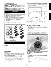
.... Knob must hold drum firmly so that it does not spin loose on spindle. 3 WARNING: Do not attempt to a firm, level surface. • Make sure there is being used. The sander comes assembled as one unit. Base Dimension and Mounting Holes ATTACH ABRASIVE SLEEVES ...8243; ABRASIVE SLEEVES: Example: 2″ • Place the 2″ table insert over spindle and onto the table. Additional parts should be bolted to operate tool until completely assembled. To install sander: • The sander must be filled with knob. If damage has occurred, a claim must be located and ...
.... Knob must hold drum firmly so that it does not spin loose on spindle. 3 WARNING: Do not attempt to a firm, level surface. • Make sure there is being used. The sander comes assembled as one unit. Base Dimension and Mounting Holes ATTACH ABRASIVE SLEEVES ...8243; ABRASIVE SLEEVES: Example: 2″ • Place the 2″ table insert over spindle and onto the table. Additional parts should be bolted to operate tool until completely assembled. To install sander: • The sander must be filled with knob. If damage has occurred, a claim must be located and ...
Operation Manual
Page 4
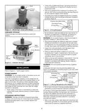
.... WARNING: This work should be plugged directly into a properly installed and grounded 3-prong grounding-type receptacle, as shown (Figure 6). POWER SOURCE WARNING: Do not connect sander to touch the terminals of the adapter must be tested by a qualified electrician. The motor is not permitted in Canada.) Where permitted, the rigid green...
.... WARNING: This work should be plugged directly into a properly installed and grounded 3-prong grounding-type receptacle, as shown (Figure 6). POWER SOURCE WARNING: Do not connect sander to touch the terminals of the adapter must be tested by a qualified electrician. The motor is not permitted in Canada.) Where permitted, the rigid green...
Operation Manual
Page 5
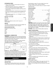
...be performed by a single pole locking rocker switch. • Remove the key to the motor is inspected. DESCRIPTION The Craftsman Oscillating Spindle Sander makes sanding irregular shapes and curves in severe eye damage. Six sizes of drums are installed as shown in wiring schematic (... fastened to the frame to fit Sears wet/dry vacuums. SPECIFICATIONS Spindle diameter Drum diameters 1″, 1½″, 2″ and 3″ Drum length 4½″ Spindle stroke 1″ Spindle oscillation 30 SPM Spindle speed 1725 RPM Table diameter 18″ Table height 14½&#...
...be performed by a single pole locking rocker switch. • Remove the key to the motor is inspected. DESCRIPTION The Craftsman Oscillating Spindle Sander makes sanding irregular shapes and curves in severe eye damage. Six sizes of drums are installed as shown in wiring schematic (... fastened to the frame to fit Sears wet/dry vacuums. SPECIFICATIONS Spindle diameter Drum diameters 1″, 1½″, 2″ and 3″ Drum length 4½″ Spindle stroke 1″ Spindle oscillation 30 SPM Spindle speed 1725 RPM Table diameter 18″ Table height 14½&#...
Operation Manual
Page 6
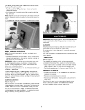
... sanding sleeve. Sawdust buildup beneath the table may prevent the spindle from unauthorized use by locking the switch. Do not allow...table on switch until the surface is similar to the contour of Craftsman wet/dry vacuums. The use the correct size table insert with ...is uniform. Dust Port Figure 9 - Figure 10 - Location of the sander. Keep the drums clean. Be certain motor is kept clean and is disconnected...permanently lubricated at the ON position, the switch can be locked from oscillating completely, causing damage to service or remove any way, have it ...
... sanding sleeve. Sawdust buildup beneath the table may prevent the spindle from unauthorized use by locking the switch. Do not allow...table on switch until the surface is similar to the contour of Craftsman wet/dry vacuums. The use the correct size table insert with ...is uniform. Dust Port Figure 9 - Figure 10 - Location of the sander. Keep the drums clean. Be certain motor is kept clean and is disconnected...permanently lubricated at the ON position, the switch can be locked from oscillating completely, causing damage to service or remove any way, have it ...
Operation Manual
Page 7
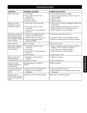
Applying too much pressure to develop full 1. Damaged or loose oscillating mechanism Excessive noise Note: Normally operating sander does make some noise Spindle and motor not aligned properly CORRECTIVE ACTION 1. Replace capacitor 1. Ease up below table insert 2. Remove sawdust with sawdust Spindle does NOT travel completely through 1″ stroke 1. Contact Sears Service Center if necessary...
Applying too much pressure to develop full 1. Damaged or loose oscillating mechanism Excessive noise Note: Normally operating sander does make some noise Spindle and motor not aligned properly CORRECTIVE ACTION 1. Replace capacitor 1. Ease up below table insert 2. Remove sawdust with sawdust Spindle does NOT travel completely through 1″ stroke 1. Contact Sears Service Center if necessary...
Operation Manual
Page 9
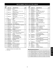
REPLACEMENT PARTS LIST FOR SANDER KEY NO. 1 2 3 4 5 6 7 8 9 10 11 12 13 14 15 16 17 18 19 20 21 22 23 24 25 26 27 28 29 30 31 32 ...;″, 2″, 3″) Table 1 Fan 1 Gasket 1 5-0.8 x 10mm Flat Head Screw 3 Fan Housing 1 5mm Flat Washer* 6 5-0.8 x 12mm Socket Head Bolt* 6 Seal 1 6003ZZ Ball Bearing* 1 Bearing Retainer 1 Spindle 1 5-0.8mm Fiber Hex Nut* 1 Bushing (set of 2) 1 5-0.8 x 40mm Socket Head Bolt* 1 3AMI-17 Retaining Ring 1 Collar 1 8mm Wavy Washer 3 61903ZZ Ball Bearing 1 3AMI-30 Retaining...
REPLACEMENT PARTS LIST FOR SANDER KEY NO. 1 2 3 4 5 6 7 8 9 10 11 12 13 14 15 16 17 18 19 20 21 22 23 24 25 26 27 28 29 30 31 32 ...;″, 2″, 3″) Table 1 Fan 1 Gasket 1 5-0.8 x 10mm Flat Head Screw 3 Fan Housing 1 5mm Flat Washer* 6 5-0.8 x 12mm Socket Head Bolt* 6 Seal 1 6003ZZ Ball Bearing* 1 Bearing Retainer 1 Spindle 1 5-0.8mm Fiber Hex Nut* 1 Bushing (set of 2) 1 5-0.8 x 40mm Socket Head Bolt* 1 3AMI-17 Retaining Ring 1 Collar 1 8mm Wavy Washer 3 61903ZZ Ball Bearing 1 3AMI-30 Retaining...


