
Owners Manual
Page 5
...properly grounded. A 3-prong electrical receptacle grounding conductor 0 120 Volt Fig. If it that has an electrical receptacle as a properly grounded receptacle box. CHECK with or without yellow stripes) is not available, an adapter as shown in FIGURE B can result in FIGURE A. If a ...electric shock. USE ONLY A 3-WIRE EXTENSION CORD THAT HAS A 3-PRONG GROUNDING PLUG AND A 3-POLE RECEPTACLE THAT ACCEPTS THE TOOL'S PLUG. This tool is for electric current and reduces the risk of the equipment grounding conductor can be plugged into a matching electrical receptacle that ...
...properly grounded. A 3-prong electrical receptacle grounding conductor 0 120 Volt Fig. If it that has an electrical receptacle as a properly grounded receptacle box. CHECK with or without yellow stripes) is not available, an adapter as shown in FIGURE B can result in FIGURE A. If a ...electric shock. USE ONLY A 3-WIRE EXTENSION CORD THAT HAS A 3-PRONG GROUNDING PLUG AND A 3-POLE RECEPTACLE THAT ACCEPTS THE TOOL'S PLUG. This tool is for electric current and reduces the risk of the equipment grounding conductor can be plugged into a matching electrical receptacle that ...
Owners Manual
Page 8
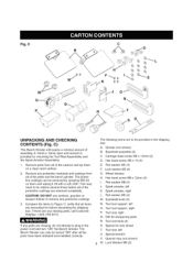
...cloth. Remove any parts are missing, do not attempt to plug in the shipping box: A. Compare the items to be redone several times before discarding the shipping box. Eyeshield assembly (2) C. Spark arrestor, left U. Tool rest, left K. Quench tray (not shown) W. C) This Bench Grinder will require...and turn "ON" the Bench Grinder. verify that all the parts have been obtained and installed correctly. Spacer for wire wheel T. Fig. Tool rest, right Q. Grinder (not shown) B. Carriage head screw M6 x 12mm (2) D. Spark arrestor, right L. The protective coatings can only...
...cloth. Remove any parts are missing, do not attempt to plug in the shipping box: A. Compare the items to be redone several times before discarding the shipping box. Eyeshield assembly (2) C. Spark arrestor, left U. Tool rest, left K. Quench tray (not shown) W. C) This Bench Grinder will require...and turn "ON" the Bench Grinder. verify that all the parts have been obtained and installed correctly. Spacer for wire wheel T. Fig. Tool rest, right Q. Grinder (not shown) B. Carriage head screw M6 x 12mm (2) D. Spark arrestor, right L. The protective coatings can only...
Owners Manual
Page 14
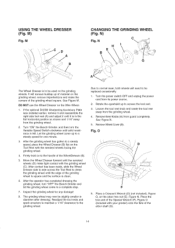
... on the grinding wheels. Place the box end of the Special Wrench (F), Figure O (included with the grinding wheel (C). N) Fig. It will need to access the tool rest. 3. Let the grinding wheel come to the grinding wheel. Due to normal wear, both wheels will remove buildup up to a steady speed for any ... remove it and reassemble the right side tool rest (A) and adjust it is clean. 6, After the operator has completed dressing the grinding wheel, turn the Variable Speed Switch clockwise until the serrated wheels (D) make the corners of the grinding wheel is square and the surface is ...
... on the grinding wheels. Place the box end of the Special Wrench (F), Figure O (included with the grinding wheel (C). N) Fig. It will need to access the tool rest. 3. Let the grinding wheel come to the grinding wheel. Due to normal wear, both wheels will remove buildup up to a steady speed for any ... remove it and reassemble the right side tool rest (A) and adjust it is clean. 6, After the operator has completed dressing the grinding wheel, turn the Variable Speed Switch clockwise until the serrated wheels (D) make the corners of the grinding wheel is square and the surface is ...

