Safety and Regulatory Information Desktops, Thin Clients, and Personal Workstations
Page 28
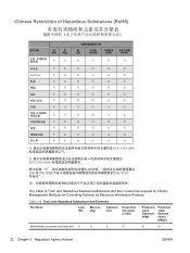
... 2-2 Toxic and Hazardous Substances and Elements Part Name Lead (Pb) Mercury (Hg) Cadmium (Cd) Hexavalent Chromium (Cr(VI)) Polybrominated biphenyls (PBB) Polybrominated diphenyl ethers (PBDE) Motherboard, processor and heat sink X O O O O O 22 Chapter 2 Regulatory Agency Notices ENWW
... 2-2 Toxic and Hazardous Substances and Elements Part Name Lead (Pb) Mercury (Hg) Cadmium (Cd) Hexavalent Chromium (Cr(VI)) Polybrominated biphenyls (PBB) Polybrominated diphenyl ethers (PBDE) Motherboard, processor and heat sink X O O O O O 22 Chapter 2 Regulatory Agency Notices ENWW

Upgrading and Servicing Guide
Page 18
4 Connect the power and data cables to a primary hard disk drive. Connect to the back of the HP Pocket Media, diskette (floppy), or hard disk drive. Connect to replace the front panel, replace the side panel, and close the PC. Connect to the PC motherboard. 5 Complete the procedures to a secondary hard disk drive (select models only). B - See "Opening and Closing the PC" on page 1. 14 Upgrading and Servicing Guide C - A B MASTER C SLAVE To CPU A -
4 Connect the power and data cables to a primary hard disk drive. Connect to the back of the HP Pocket Media, diskette (floppy), or hard disk drive. Connect to replace the front panel, replace the side panel, and close the PC. Connect to the PC motherboard. 5 Complete the procedures to a secondary hard disk drive (select models only). B - See "Opening and Closing the PC" on page 1. 14 Upgrading and Servicing Guide C - A B MASTER C SLAVE To CPU A -
Upgrading and Servicing Guide
Page 25
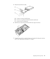
B - 5 Attach the hard disk drive cables. Connect to replace the front panel, replace the side panel, and close the PC. Connect to the PC motherboard. 6 Attach the two screws that secure the hard disk drive cage to the chassis. 7 Complete the procedures to a primary hard disk drive. Upgrading and Servicing Guide 21 A B MASTER C SLAVE To CPU A - See "Opening and Closing the PC" on page 1. Connect to a secondary hard disk drive (select models only). C -
B - 5 Attach the hard disk drive cables. Connect to replace the front panel, replace the side panel, and close the PC. Connect to the PC motherboard. 6 Attach the two screws that secure the hard disk drive cage to the chassis. 7 Complete the procedures to a primary hard disk drive. Upgrading and Servicing Guide 21 A B MASTER C SLAVE To CPU A - See "Opening and Closing the PC" on page 1. Connect to a secondary hard disk drive (select models only). C -
Upgrading and Servicing Guide
Page 26
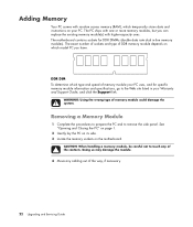
...(s) with random access memory (RAM), which type and speed of memory module your PC uses, and for DDR DIMMs (double data rate dual in your PC. DDR DIM To determine which temporarily stores data and instructions on the motherboard. The motherboard contains sockets for specific memory module information and specifications, go to the Web...
...(s) with random access memory (RAM), which type and speed of memory module your PC uses, and for DDR DIMMs (double data rate dual in your PC. DDR DIM To determine which temporarily stores data and instructions on the motherboard. The motherboard contains sockets for specific memory module information and specifications, go to the Web...

Upgrading and Servicing Guide
Page 29
Removing an Add-in Card 1 Complete the procedures to prepare the PC and to scrape the card against the other components. Hold the card at ... connectors pull free from the bracket cover for the add-in card slots, and then remove the bracket cover. 4 Inside the PC, locate the add-in card slot cover. 5 Remove the slot cover. Be sure not to remove the side panel. A... See "Opening and Closing the PC" on page 1. 2 Gently lay the PC on its side. 3 On the back of the sharp edges on the add-in card slots on the motherboard. WARNING: Be careful of the PC, remove the screw from the socket...
Removing an Add-in Card 1 Complete the procedures to prepare the PC and to scrape the card against the other components. Hold the card at ... connectors pull free from the bracket cover for the add-in card slots, and then remove the bracket cover. 4 Inside the PC, locate the add-in card slot cover. 5 Remove the slot cover. Be sure not to remove the side panel. A... See "Opening and Closing the PC" on page 1. 2 Gently lay the PC on its side. 3 On the back of the sharp edges on the add-in card slots on the motherboard. WARNING: Be careful of the PC, remove the screw from the socket...

Upgrading and Servicing Guide
Page 31
...the procedure to replace the side panel, and to weaken, the date and time may be incorrect. See "Opening and Closing the PC" on page 1. 2 Gently lay the PC on page 22. 5 To remove the battery, push the latch away from the battery and lift the battery from the socket...., replace it with a CR2032 lithium battery (3 volt, 220mAH rating) or an equivalent battery. See "Opening and Closing the PC" on the motherboard provides backup power for the PC's timekeeping ability. Replacing the Battery A lithium battery on page 1. The battery has an estimated life expectancy of explosion if the...
...the procedure to replace the side panel, and to weaken, the date and time may be incorrect. See "Opening and Closing the PC" on page 1. 2 Gently lay the PC on page 22. 5 To remove the battery, push the latch away from the battery and lift the battery from the socket...., replace it with a CR2032 lithium battery (3 volt, 220mAH rating) or an equivalent battery. See "Opening and Closing the PC" on the motherboard provides backup power for the PC's timekeeping ability. Replacing the Battery A lithium battery on page 1. The battery has an estimated life expectancy of explosion if the...

Start Here Guide
Page 10
..., digital camera, or another device with a USB connector. 4 Start Here You must use the Audio In connector, which is connected to the motherboard and located on the back of the computer, to record audio only. (Select models only.) Secondary Right audio input connector (red). You must use... the Audio In connector, which is connected to the motherboard and located on the back of the computer, to record audio only. (Select models only.) Headphones Out connector (green) to connect to headphones...
..., digital camera, or another device with a USB connector. 4 Start Here You must use the Audio In connector, which is connected to the motherboard and located on the back of the computer, to record audio only. (Select models only.) Secondary Right audio input connector (red). You must use... the Audio In connector, which is connected to the motherboard and located on the back of the computer, to record audio only. (Select models only.) Headphones Out connector (green) to connect to headphones...

Start Here Guide
Page 12
...: Audio can be recorded by using this primary left audio input from a set-top box output connector. Microphone In (Mic) (pink) to connect to the motherboard. Audio Line Out (green) to connect rear speakers in a multichannel audio configuration. Line Rear (black) connector to connect front speakers. Primary left audio input connector...
...: Audio can be recorded by using this primary left audio input from a set-top box output connector. Microphone In (Mic) (pink) to connect to the motherboard. Audio Line Out (green) to connect rear speakers in a multichannel audio configuration. Line Rear (black) connector to connect front speakers. Primary left audio input connector...

Start Here Guide
Page 13
... (blue) display output connector connects to a TV. Setting Up Your Computer 7 Modem (Line In RJ-11) (select models only). Plug the other end to the motherboard. Digital Audio Out Digital audio input (white) connects to improve your telephone line wall jack connector. NOTE: Audio can be recorded by using this primary...
... (blue) display output connector connects to a TV. Setting Up Your Computer 7 Modem (Line In RJ-11) (select models only). Plug the other end to the motherboard. Digital Audio Out Digital audio input (white) connects to improve your telephone line wall jack connector. NOTE: Audio can be recorded by using this primary...


