Compaq Presario SA4000 Power Supply - Desktop PC
Compaq Presario SA4000 Power Supply

View Results Below
Free Compaq Presario SA4000 manuals!
Problems with Compaq Presario SA4000?
Ask a Question
Free Compaq Presario SA4000 manuals!
Problems with Compaq Presario SA4000?
Ask a Question
Related Manual Pages


Similar Questions


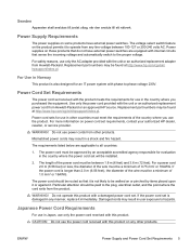
Power Supply
power switch is bad so i jumped it from the green to gound at the ATX Fan comes on but no POST
power switch is bad so i jumped it from the green to gound at the ATX Fan comes on but no POST
(Posted by ddroze 12 years ago)