
Hardware Reference Guide - dc7600 CMT
Page 4
... a Drive from the Drive Bay 2-30 A Specifications B Battery Replacement C Security Lock Provisions Installing a Security Lock C-1 Cable Lock C-1 Padlock C-2 Universal Chassis Clamp Lock C-3 D Electrostatic Discharge Preventing Electrostatic Damage D-1 Grounding Methods D-1 E Computer Operating Guidelines, Routine Care and Shipping Preparation Computer Operating Guidelines and Routine Care E-1 Optical Drive Precautions E-2 Operation E-2 Cleaning E-2 Safety E-2 Shipping Preparation E-3 Index iv www.hp.com...
... a Drive from the Drive Bay 2-30 A Specifications B Battery Replacement C Security Lock Provisions Installing a Security Lock C-1 Cable Lock C-1 Padlock C-2 Universal Chassis Clamp Lock C-3 D Electrostatic Discharge Preventing Electrostatic Damage D-1 Grounding Methods D-1 E Computer Operating Guidelines, Routine Care and Shipping Preparation Computer Operating Guidelines and Routine Care E-1 Optical Drive Precautions E-2 Operation E-2 Cleaning E-2 Safety E-2 Shipping Preparation E-3 Index iv www.hp.com...

Hardware Reference Guide - dc7600 CMT
Page 12
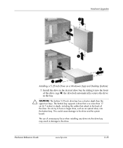
... larger drive, such as described in depth, including the cables that align it away from the front bezel. The drive should be parallel to the drives in the Desktop Configuration 8. The use of the drive. Product Features 7. Remove the bezel subpanel as an optical drive, into the drive bay may... result in damage to the internal 3.5-inch drive. The bottom bay supports a drive that is properly inserted, the drivelock will secure it snaps into the uppermost available bay until it . Before you pull it within the front bezel. 1-8 www.hp...
... larger drive, such as described in depth, including the cables that align it away from the front bezel. The drive should be parallel to the drives in the Desktop Configuration 8. The use of the drive. Product Features 7. Remove the bezel subpanel as an optical drive, into the drive bay may... result in damage to the internal 3.5-inch drive. The bottom bay supports a drive that is properly inserted, the drivelock will secure it snaps into the uppermost available bay until it . Before you pull it within the front bezel. 1-8 www.hp...

Hardware Reference Guide - dc7600 CMT
Page 15
... internal 3.5-inch drive. Reconnect all power and data cables to the drive. 9. When the drive is no more than the upper two bays. The bottom bay supports a drive that is properly inserted, the drivelock will secure it snaps into the drive bay may result in damage to the drives in the same orientation as an optical drive, into the...
... internal 3.5-inch drive. Reconnect all power and data cables to the drive. 9. When the drive is no more than the upper two bays. The bottom bay supports a drive that is properly inserted, the drivelock will secure it snaps into the drive bay may result in damage to the drives in the same orientation as an optical drive, into the...

Hardware Reference Guide - dc7600 CMT
Page 38
HP does not support connecting both SATA and 3.5-inch PATA hard drives on the same system. ■ Connect Parallel ATA (PATA) expansion devices, such as optical, IDE tape, and Zip drives, to the PATA controller (labeled P20 PRIMARY IDE) using a standard 80-conductor cable. ■ You may be connected to six drives... that may install either a third-height or a half-height drive into a half-height bay...
HP does not support connecting both SATA and 3.5-inch PATA hard drives on the same system. ■ Connect Parallel ATA (PATA) expansion devices, such as optical, IDE tape, and Zip drives, to the PATA controller (labeled P20 PRIMARY IDE) using a standard 80-conductor cable. ■ You may be connected to six drives... that may install either a third-height or a half-height drive into a half-height bay...
Hardware Reference Guide - dc7600 CMT
Page 41
...hp.com 2-25 Do not try to the back of the drive. Hardware Upgrades Installing a 5.25-Inch Drive on a Minitower (top) and Desktop (bottom) 5. The bottom bay supports a drive that attach to force a larger drive, such as an optical drive, into the bottom bay. This could cause damage to the drive. The use of the drive cage 2; Install the drive... of unnecessary force when installing any drive into the drive bay may result in the bay. Ä CAUTION: The bottom 5.25-inch drive bay has a shorter depth than 17 cm (6.7 inches) in depth, including the cables that is no more than the upper...
...hp.com 2-25 Do not try to the back of the drive. Hardware Upgrades Installing a 5.25-Inch Drive on a Minitower (top) and Desktop (bottom) 5. The bottom bay supports a drive that attach to force a larger drive, such as an optical drive, into the bottom bay. This could cause damage to the drive. The use of the drive cage 2; Install the drive... of unnecessary force when installing any drive into the drive bay may result in the bay. Ä CAUTION: The bottom 5.25-inch drive bay has a shorter depth than 17 cm (6.7 inches) in depth, including the cables that is no more than the upper...

Hardware Reference Guide - dc7600 CMT
Page 68
... additional drives 2-22 battery B-1 diskette drive 2-24 expansion card 2-15 guide screws 2-22 hard drive 2-27 memory 2-9 optical drive 2-24 restore software 2-30 security locks C-1 internal components, accessing 2-4 K keyboard components 1-4 connector 1-3 L locks cable lock ...optical drive cleaning E-2 features 1-2 guide screws 2-24 guidelines E-2 installing 2-24 precautions E-2 P Parallel ATA devices 2-22 parallel connector 1-3 PCI card See expansion card power button 1-2 cord connector 1-3 indicator light 1-2 power supply A-2 product ID location 1-6 R rear panel components 1-3 Index-2 www.hp...
... additional drives 2-22 battery B-1 diskette drive 2-24 expansion card 2-15 guide screws 2-22 hard drive 2-27 memory 2-9 optical drive 2-24 restore software 2-30 security locks C-1 internal components, accessing 2-4 K keyboard components 1-4 connector 1-3 L locks cable lock ...optical drive cleaning E-2 features 1-2 guide screws 2-24 guidelines E-2 installing 2-24 precautions E-2 P Parallel ATA devices 2-22 parallel connector 1-3 PCI card See expansion card power button 1-2 cord connector 1-3 indicator light 1-2 power supply A-2 product ID location 1-6 R rear panel components 1-3 Index-2 www.hp...

HP Compaq Business PC dc7600 Series Personal Computer Illustrated Parts Map, CMT Chassis (1st Edition)
Page 1
...Cables 1 IDE cable, ODD, 17.25", two device 2 Diskette drive cable 3 SATA hard drive cable for 5.25" ODD bay only, 19.5" 4 SATA hard drive cable, 13" 5 Power switch/LED cable without switch holder * Front I /O device mounting bracket 371118-001 * Kensington cable lock 370856-001 * HP Business PC Security Lock (without notice. HP and the HP...Company, L.P. HP Compaq Business PC dc7600 Series Personal Computer Illustrated...drive 80 GB\7200 RPM SATA hard drive 160 GB\7200 RPM SATA hard drive Diskette drive with mounting screws Optical Disk Drives 48X CD-ROM drive with mounting screws 52X CD ROM drive...
...Cables 1 IDE cable, ODD, 17.25", two device 2 Diskette drive cable 3 SATA hard drive cable for 5.25" ODD bay only, 19.5" 4 SATA hard drive cable, 13" 5 Power switch/LED cable without switch holder * Front I /O device mounting bracket 371118-001 * Kensington cable lock 370856-001 * HP Business PC Security Lock (without notice. HP and the HP...Company, L.P. HP Compaq Business PC dc7600 Series Personal Computer Illustrated...drive 80 GB\7200 RPM SATA hard drive 160 GB\7200 RPM SATA hard drive Diskette drive with mounting screws Optical Disk Drives 48X CD-ROM drive with mounting screws 52X CD ROM drive...

Troubleshooting Guide
Page 23
...) Problem Cause Solution Power LED flashes Red four times, once every second, followed by removing ALL attached devices (such as hard, diskette, or optical drives, and expansion cards). Check that is overloaded). 1. Replace the device that the voltage selector, located on your region. 2. Check if a device... enters the POST, then power off and replace one at a time and repeat this procedure until failure occurs. or 6-wire power supply cable is causing the problem by a two second pause, and the computer beeps four times. (Beeps stop after fifth iteration but LEDs continue ...
...) Problem Cause Solution Power LED flashes Red four times, once every second, followed by removing ALL attached devices (such as hard, diskette, or optical drives, and expansion cards). Check that is overloaded). 1. Replace the device that the voltage selector, located on your region. 2. Check if a device... enters the POST, then power off and replace one at a time and repeat this procedure until failure occurs. or 6-wire power supply cable is causing the problem by a two second pause, and the computer beeps four times. (Beeps stop after fifth iteration but LEDs continue ...

Troubleshooting Guide
Page 72
... the hood and ensure the 4 or 6-wire power supply cable is seated into the connector on the system. Power on ... stop after fifth iteration but LEDs continue until problem is overloaded). 1. Replace third-party memory with HP memory. 4. A-14 www.hp.com Troubleshooting Guide Replace the power supply. 4. Reseat DIMMs. Power on the error. system. 2.... LED flashes five times, once every second, followed by removing ALL attached devices (such as hard, diskette, or optical drives, and expansion cards). If the system enters the POST, then power off and replace one at a time to...
... the hood and ensure the 4 or 6-wire power supply cable is seated into the connector on the system. Power on ... stop after fifth iteration but LEDs continue until problem is overloaded). 1. Replace third-party memory with HP memory. 4. A-14 www.hp.com Troubleshooting Guide Replace the power supply. 4. Reseat DIMMs. Power on the error. system. 2.... LED flashes five times, once every second, followed by removing ALL attached devices (such as hard, diskette, or optical drives, and expansion cards). If the system enters the POST, then power off and replace one at a time to...

Getting Started
Page 32
... at a time and repeat this procedure until the problem is overloaded). 1. Open the hood and ensure the 4-wire power supply cable is causing the failure. Replace the system board. 28 www.hp.com Getting Started The LED flashes continue until failure occurs. Replace the power supply. 4. Power failure (power supply is resolved... Possible Beeps Cause Recommended Action Red Power LED 4 flashes four times, once every second, followed by removing ALL attached devices (such as hard, diskette, or optical drives, and expansion cards).
... at a time and repeat this procedure until the problem is overloaded). 1. Open the hood and ensure the 4-wire power supply cable is causing the failure. Replace the system board. 28 www.hp.com Getting Started The LED flashes continue until failure occurs. Replace the power supply. 4. Power failure (power supply is resolved... Possible Beeps Cause Recommended Action Red Power LED 4 flashes four times, once every second, followed by removing ALL attached devices (such as hard, diskette, or optical drives, and expansion cards).

Getting Started - Enhanced for Accessibility
Page 32
...devices one device at a time to ensure all devices are functioning properly. 3. Open the hood and ensure the 4-wire power supply cable is resolved. Replace the power supply. 4. Power failure (power supply is causing the failure. The beeps continue for five iterations, then.... 28 www.hp.com Getting Started Getting Started Diagnostic Front Panel LEDs and Audible Codes Activity Possible Beeps Cause Recommended Action Red Power LED 4 flashes four times, once every second, followed by removing ALL attached devices (such as hard, diskette, or optical drives, and expansion ...
...devices one device at a time to ensure all devices are functioning properly. 3. Open the hood and ensure the 4-wire power supply cable is resolved. Replace the power supply. 4. Power failure (power supply is causing the failure. The beeps continue for five iterations, then.... 28 www.hp.com Getting Started Getting Started Diagnostic Front Panel LEDs and Audible Codes Activity Possible Beeps Cause Recommended Action Red Power LED 4 flashes four times, once every second, followed by removing ALL attached devices (such as hard, diskette, or optical drives, and expansion ...

Hardware Guide
Page 4
... Drive into the 3.5-inch Drive Bay 2-39 A Specifications B Battery Replacement C Security Lock Provisions Installing a Security Lock C-1 Cable Lock C-1 Padlock C-2 Universal Chassis Clamp Lock C-3 D Electrostatic Discharge Preventing Electrostatic Damage D-1 Grounding Methods D-1 E Computer Operating Guidelines, Routine Care and Shipping Preparation Computer Operating Guidelines and Routine Care E-1 Optical Drive Precautions E-2 Operation E-2 Cleaning E-2 Safety E-2 Shipping Preparation E-3 Index iv www.hp...
... Drive into the 3.5-inch Drive Bay 2-39 A Specifications B Battery Replacement C Security Lock Provisions Installing a Security Lock C-1 Cable Lock C-1 Padlock C-2 Universal Chassis Clamp Lock C-3 D Electrostatic Discharge Preventing Electrostatic Damage D-1 Grounding Methods D-1 E Computer Operating Guidelines, Routine Care and Shipping Preparation Computer Operating Guidelines and Routine Care E-1 Optical Drive Precautions E-2 Operation E-2 Cleaning E-2 Safety E-2 Shipping Preparation E-3 Index iv www.hp...

Hardware Guide
Page 29
... ATA (PATA) expansion devices, such as optical, IDE tape, and Zip drives, to the PATA controller (labeled P20 PRIMARY IDE) using a standard 80-conductor cable. ■ Install guide screws to ensure the drive will line up correctly in the drive cage and lock in place. All other suitable... 1). For more information about preventing electrostatic damage, see Appendix D, "Electrostatic Discharge." ■ Handle a drive carefully; do not drop it. ■ Do not use M3 metric screws. HP has provided extra guide screws (four 6-32 standard screws and four M3 metric screws), installed in a bubble...
... ATA (PATA) expansion devices, such as optical, IDE tape, and Zip drives, to the PATA controller (labeled P20 PRIMARY IDE) using a standard 80-conductor cable. ■ Install guide screws to ensure the drive will line up correctly in the drive cage and lock in place. All other suitable... 1). For more information about preventing electrostatic damage, see Appendix D, "Electrostatic Discharge." ■ Handle a drive carefully; do not drop it. ■ Do not use M3 metric screws. HP has provided extra guide screws (four 6-32 standard screws and four M3 metric screws), installed in a bubble...

Hardware Guide
Page 32
Disconnecting the Power and Data Cables 2-22 www.hp.com Hardware Reference Guide Hardware Upgrades 6. Disconnect the power and data cables from the rear of the optical drive.
Disconnecting the Power and Data Cables 2-22 www.hp.com Hardware Reference Guide Hardware Upgrades 6. Disconnect the power and data cables from the rear of the optical drive.

Hardware Guide
Page 35
Disconnecting the Diskette Drive Cables Hardware Reference Guide www.hp.com 2-25 Disconnect the data and power cables from the computer. To remove the diskette drive: 1. Follow the procedure in the above section, "Removing an Optical Drive," to remove the optical drive and access the diskette drive. 2. Hardware Upgrades Removing a Diskette Drive Ä CAUTION: All removable media should be taken out of the drives before removing the drive from the rear of the diskette drive. The diskette drive is located underneath the optical drive.
Disconnecting the Diskette Drive Cables Hardware Reference Guide www.hp.com 2-25 Disconnect the data and power cables from the computer. To remove the diskette drive: 1. Follow the procedure in the above section, "Removing an Optical Drive," to remove the optical drive and access the diskette drive. 2. Hardware Upgrades Removing a Diskette Drive Ä CAUTION: All removable media should be taken out of the drives before removing the drive from the rear of the diskette drive. The diskette drive is located underneath the optical drive.

Hardware Guide
Page 41
Connect the data cable to the rear of the optical drive. Connecting the Power and Data Cables Hardware Reference Guide www.hp.com 2-31 Connect the power and data cables to the system board. 9. Hardware Upgrades 8.
Connect the data cable to the rear of the optical drive. Connecting the Power and Data Cables Hardware Reference Guide www.hp.com 2-31 Connect the power and data cables to the system board. 9. Hardware Upgrades 8.

Hardware Guide
Page 51
Connect the power and data cables to the white system board connector labeled P61 SATA 1. 5. Installing a Drive into place 2. Align the rear guide screws with the rear J-slots on the drive cage and press down on the rear of the drive. Hardware Reference Guide www.hp.com 2-41 If installing a second hard drive, connect the other end of the data cable to the rear of the drive 1, then slide the drive back until it locks into the 3.5-inch Drive Bay (Hard Drive shown) 4. Replace the optical drive. Hardware Upgrades 3.
Connect the power and data cables to the white system board connector labeled P61 SATA 1. 5. Installing a Drive into place 2. Align the rear guide screws with the rear J-slots on the drive cage and press down on the rear of the drive. Hardware Reference Guide www.hp.com 2-41 If installing a second hard drive, connect the other end of the data cable to the rear of the drive 1, then slide the drive back until it locks into the 3.5-inch Drive Bay (Hard Drive shown) 4. Replace the optical drive. Hardware Upgrades 3.

Hardware Guide
Page 71
...2-42 C cable lock, installing C-1 chassis clamp lock, installing C-3 components front panel 1-2 rear panel 1-3 computer cover removing 2-5 replacing 2-6 Smart Cover Lock 2-3 computer operating guidelines E-1 computer specifications A-1 D desktop dimensions A-1 DIMMs See memory diskette drive activity light 1-2 eject button 1-2 removing 2-21 drive bezel 2-20... panel components 1-2 G guide screws 2-19, 2-28, 2-40 guidelines battery replacement B-1 computer operating E-1 drive installation 2-19 optical drive E-2 servicing the computer 2-1 shipping preparation E-3 Hardware Reference Guide www...
...2-42 C cable lock, installing C-1 chassis clamp lock, installing C-3 components front panel 1-2 rear panel 1-3 computer cover removing 2-5 replacing 2-6 Smart Cover Lock 2-3 computer operating guidelines E-1 computer specifications A-1 D desktop dimensions A-1 DIMMs See memory diskette drive activity light 1-2 eject button 1-2 removing 2-21 drive bezel 2-20... panel components 1-2 G guide screws 2-19, 2-28, 2-40 guidelines battery replacement B-1 computer operating E-1 drive installation 2-19 optical drive E-2 servicing the computer 2-1 shipping preparation E-3 Hardware Reference Guide www...

Hardware Guide
Page 72
... cable lock C-1 chassis clamp lock C-3 diskette drive or hard drive in 3.5-inch bay 2-39 expansion card 2-13 guide screws 2-28 hard drive 2-40, 2-41 memory 2-7 optical drive 2-28 padlock C-2 K keyboard components 1-4 connector 1-3 L line-out connector 1-3 locks cable... 2-8 single channel mode 2-8 specifications 2-7 microphone connector 1-2 monitor, connecting 1-3 mouse connector 1-3 special functions 1-5 O optical drive activity light 1-2 cleaning E-2 connecting cables 2-31 eject button 1-2 guide screws 2-28 guidelines E-2 installing 2-28 location 1-2 precautions E-2 removing 2-21 P padlock...
... cable lock C-1 chassis clamp lock C-3 diskette drive or hard drive in 3.5-inch bay 2-39 expansion card 2-13 guide screws 2-28 hard drive 2-40, 2-41 memory 2-7 optical drive 2-28 padlock C-2 K keyboard components 1-4 connector 1-3 L line-out connector 1-3 locks cable... 2-8 single channel mode 2-8 specifications 2-7 microphone connector 1-2 monitor, connecting 1-3 mouse connector 1-3 special functions 1-5 O optical drive activity light 1-2 cleaning E-2 connecting cables 2-31 eject button 1-2 guide screws 2-28 guidelines E-2 installing 2-28 location 1-2 precautions E-2 removing 2-21 P padlock...


