
Safety and Regulatory Information Desktops, Thin Clients, and Personal Workstations
Page 18
...locations, and so on. Some of these notices may void the user's authority to operate the equipment. Such restrictions may be determined by turning the equipment off and on, the user is encouraged to try to correct the interference by Hewlett-Packard Company may not apply to your ... interference will not occur in accordance with the limits for a Class B digital device, pursuant to Part 15 of the FCC Rules. If you turn it on a circuit different from that the Coaxial cable shield shall be made with shielded cables with FCC Rules and Regulations. 12 Chapter 2 Regulatory...
...locations, and so on. Some of these notices may void the user's authority to operate the equipment. Such restrictions may be determined by turning the equipment off and on, the user is encouraged to try to correct the interference by Hewlett-Packard Company may not apply to your ... interference will not occur in accordance with the limits for a Class B digital device, pursuant to Part 15 of the FCC Rules. If you turn it on a circuit different from that the Coaxial cable shield shall be made with shielded cables with FCC Rules and Regulations. 12 Chapter 2 Regulatory...
Hardware Reference Guide - dc7600 CMT
Page 11
... bays. 6. Remove the computer access panel as described in the "Removing the Computer Access Panel" section. 4. Turn off the computer properly through the operating system and turn off any external devices. 3. Disconnect all power and data cables from a Minitower to unlock the lock. 2. ...To release the drives from the Drive Bays (Minitower) Hardware Reference Guide www.hp.com 1-7 Releasing the 5.25-inch Drives...
... bays. 6. Remove the computer access panel as described in the "Removing the Computer Access Panel" section. 4. Turn off the computer properly through the operating system and turn off any external devices. 3. Disconnect all power and data cables from a Minitower to unlock the lock. 2. ...To release the drives from the Drive Bays (Minitower) Hardware Reference Guide www.hp.com 1-7 Releasing the 5.25-inch Drives...

Hardware Reference Guide - dc7600 CMT
Page 12
Repeat this step for each drive into the chassis, turn the drive so that align it snaps into the uppermost available bay until it within the front bezel. 1-8 www.hp.com Hardware Reference Guide This could damage the pins that it is properly inserted, the drivelock will secure it away from the front...
Repeat this step for each drive into the chassis, turn the drive so that align it snaps into the uppermost available bay until it within the front bezel. 1-8 www.hp.com Hardware Reference Guide This could damage the pins that it is properly inserted, the drivelock will secure it away from the front...
Hardware Reference Guide - dc7600 CMT
Page 14
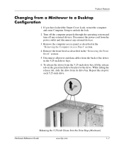
Remove the computer access panel as shown. To release the drives from the Drive Bays (Desktop) www.hp.com Hardware Reference Guide Disconnect the power cord from a Desktop to unlock the lock. 2. If you have locked the Smart Cover Lock, restart the computer ... the short yellow drivelock as described in the "Removing the Front Bezel" section. 5. Product Features Changing from the power outlet and disconnect any external devices. Turn off the computer properly through the operating system and...
Remove the computer access panel as shown. To release the drives from the Drive Bays (Desktop) www.hp.com Hardware Reference Guide Disconnect the power cord from a Desktop to unlock the lock. 2. If you have locked the Smart Cover Lock, restart the computer ... the short yellow drivelock as described in the "Removing the Front Bezel" section. 5. Product Features Changing from the power outlet and disconnect any external devices. Turn off the computer properly through the operating system and...

Hardware Reference Guide - dc7600 CMT
Page 15
... it snaps into the bottom bay. When the drive is in the 5.25-inch drive bays. Repeat this step for each drive into the chassis, turn it so that attach to the drives in the same orientation as an optical drive, into place. This could cause damage to force a larger drive... bay may result in the Minitower Configuration 8. The bottom bay supports a drive that is no more than the upper two bays. Hardware Reference Guide www.hp.com 1-11 Do not try to the drive and the system board. Product Features 7.
... it snaps into the bottom bay. When the drive is in the 5.25-inch drive bays. Repeat this step for each drive into the chassis, turn it so that attach to the drives in the same orientation as an optical drive, into place. This could cause damage to force a larger drive... bay may result in the Minitower Configuration 8. The bottom bay supports a drive that is no more than the upper two bays. Hardware Reference Guide www.hp.com 1-11 Do not try to the drive and the system board. Product Features 7.

Hardware Reference Guide - dc7600 CMT
Page 19
... with the Smart Cover Lock engaged: 1. Removing the Smart Cover Lock Screws 4. Refer to the chassis. Remove the access panel. Hardware Reference Guide www.hp.com 2-3 Turn off the computer properly through the operating system and turn off any external devices. 3. Hardware Upgrades To open the access panel with the tamper-proof screws.
... with the Smart Cover Lock engaged: 1. Removing the Smart Cover Lock Screws 4. Refer to the chassis. Remove the access panel. Hardware Reference Guide www.hp.com 2-3 Turn off the computer properly through the operating system and turn off any external devices. 3. Hardware Upgrades To open the access panel with the tamper-proof screws.

Hardware Reference Guide - dc7600 CMT
Page 20
... disconnect any external devices. 3. Lift up on its large base for greater stability. 5. Removing the Computer Access Panel 2-4 www.hp.com Hardware Reference Guide If you have locked the Smart Cover Lock, restart the computer and enter Computer Setup to unlock the lock.... 2. Turn off the computer properly through the operating system and turn off any external devices. Ä CAUTION: Before removing the computer access panel, ensure that the power cord is turned off the unit 2. Hardware Upgrades Removing the Computer Access ...
... disconnect any external devices. 3. Lift up on its large base for greater stability. 5. Removing the Computer Access Panel 2-4 www.hp.com Hardware Reference Guide If you have locked the Smart Cover Lock, restart the computer and enter Computer Setup to unlock the lock.... 2. Turn off the computer properly through the operating system and turn off any external devices. Ä CAUTION: Before removing the computer access panel, ensure that the power cord is turned off the unit 2. Hardware Upgrades Removing the Computer Access ...

Hardware Reference Guide - dc7600 CMT
Page 22
Hardware Upgrades Removing the Front Bezel 1. Push up on the two release tabs 1, then rotate the front bezel away from the power outlet and disconnect any external devices. Turn off the computer properly through the operating system and turn off any external devices. 3. Disconnect the power cord from the chassis to unlock the lock. 2. Removing the Front Bezel 2-6 www.hp.com Hardware Reference Guide Remove the computer access panel. 4. If you have locked the Smart Cover Lock, restart the computer and enter Computer Setup to release it 2.
Hardware Upgrades Removing the Front Bezel 1. Push up on the two release tabs 1, then rotate the front bezel away from the power outlet and disconnect any external devices. Turn off the computer properly through the operating system and turn off any external devices. 3. Disconnect the power cord from the chassis to unlock the lock. 2. Removing the Front Bezel 2-6 www.hp.com Hardware Reference Guide Remove the computer access panel. 4. If you have locked the Smart Cover Lock, restart the computer and enter Computer Setup to release it 2.
Hardware Reference Guide - dc7600 CMT
Page 24
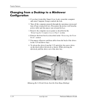
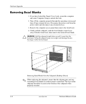
If you pull it within the front bezel. Turn off the computer properly through the operating system and turn off any external devices. 3. Disconnect the power cord from the front bezel. Removing Bezel Blanks from the Subpanel (Desktop Shown) ✎ When replacing the subpanel...the subpanel, with the bezel blanks secured in their proper orientation. Pulling the subpanel away at the bottom of the subpanel when properly oriented. 2-8 www.hp.com Hardware Reference Guide The logo on the subpanel should be located at an angle could damage the pins that the aligning pins and any...
If you pull it within the front bezel. Turn off the computer properly through the operating system and turn off any external devices. 3. Disconnect the power cord from the front bezel. Removing Bezel Blanks from the Subpanel (Desktop Shown) ✎ When replacing the subpanel...the subpanel, with the bezel blanks secured in their proper orientation. Pulling the subpanel away at the bottom of the subpanel when properly oriented. 2-8 www.hp.com Hardware Reference Guide The logo on the subpanel should be located at an angle could damage the pins that the aligning pins and any...

Hardware Reference Guide - dc7600 CMT
Page 28
... power cord from hot surfaces, allow the internal system components to cool before touching. 2-12 www.hp.com Hardware Reference Guide Remove the computer access panel. 5. Turn off the computer properly through the operating system and turn off any external devices. 4. When upgrading the memory, it is important to use memory modules with...
... power cord from hot surfaces, allow the internal system components to cool before touching. 2-12 www.hp.com Hardware Reference Guide Remove the computer access panel. 5. Turn off the computer properly through the operating system and turn off any external devices. 4. When upgrading the memory, it is important to use memory modules with...

Hardware Reference Guide - dc7600 CMT
Page 30
The computer should automatically recognize the additional memory the next time you normally lock the Smart Cover Lock, use Computer Setup to install any additional modules. 9. If you turn on the computer. 2-14 www.hp.com Hardware Reference Guide Repeat steps 6 and 7 for to relock the lock and enable the Smart Cover Sensor. Replace the access panel. 10. Hardware Upgrades 8.
The computer should automatically recognize the additional memory the next time you normally lock the Smart Cover Lock, use Computer Setup to install any additional modules. 9. If you turn on the computer. 2-14 www.hp.com Hardware Reference Guide Repeat steps 6 and 7 for to relock the lock and enable the Smart Cover Sensor. Replace the access panel. 10. Hardware Upgrades 8.

Hardware Reference Guide - dc7600 CMT
Page 32
... computer properly through the operating system and turn off any external devices. 4. Remove the computer access panel. 5. Push down and out on the back of the computer chassis. 6. Locate the correct vacant expansion ... expansion card retention latch up. Disconnect the power cord from the power outlet, then disconnect any external devices. 3. Opening the Expansion Slot Retainer 2-16 www.hp.com Hardware Reference Guide If you have locked the Smart Cover Lock, restart the computer and enter Computer Setup to unlock the lock. 2. Hardware Upgrades...
... computer properly through the operating system and turn off any external devices. 4. Remove the computer access panel. 5. Push down and out on the back of the computer chassis. 6. Locate the correct vacant expansion ... expansion card retention latch up. Disconnect the power cord from the power outlet, then disconnect any external devices. 3. Opening the Expansion Slot Retainer 2-16 www.hp.com Hardware Reference Guide If you have locked the Smart Cover Lock, restart the computer and enter Computer Setup to unlock the lock. 2. Hardware Upgrades...

Hardware Reference Guide - dc7600 CMT
Page 39
...: ■ If you are inserting or removing a hard drive, shut down the operating system properly, turn off the computer, and unplug the power cord. While handling a drive, avoid touching the connector. Hardware Reference Guide www.hp.com 2-23 Hardware Upgrades Ä CAUTION: To prevent loss of work and damage to liquids, temperature...
...: ■ If you are inserting or removing a hard drive, shut down the operating system properly, turn off the computer, and unplug the power cord. While handling a drive, avoid touching the connector. Hardware Reference Guide www.hp.com 2-23 Hardware Upgrades Ä CAUTION: To prevent loss of work and damage to liquids, temperature...

Hardware Reference Guide - dc7600 CMT
Page 40
... computer properly through the operating system and turn off any external devices. Disconnect the power cord from the power outlet and remove the computer access panel. 3. Remove the front bezel. 4. Install two guide ...screws in the lower holes on the diskette drive bracket under the access panel. Eight extra metric guide screws are black. 2-24 www.hp.com Hardware Reference Guide The HP-supplied metric screws are provided on each side of the drive 1. ✎ Optical and diskette drives use M3 metric guide screws. Hardware...
... computer properly through the operating system and turn off any external devices. Disconnect the power cord from the power outlet and remove the computer access panel. 3. Remove the front bezel. 4. Install two guide ...screws in the lower holes on the diskette drive bracket under the access panel. Eight extra metric guide screws are black. 2-24 www.hp.com Hardware Reference Guide The HP-supplied metric screws are provided on each side of the drive 1. ✎ Optical and diskette drives use M3 metric guide screws. Hardware...

Hardware Reference Guide - dc7600 CMT
Page 43
... on each side of which are black. The HP-supplied metric screws are installed on the diskette drive bracket under the access panel. Hardware Reference Guide www.hp.com 2-27 To install a hard drive in a 3.5-inch drive bay: 1. Turn off the computer properly through the operating system and... turn off any external devices. All other drives use M3 metric screws, eight of...
... on each side of which are black. The HP-supplied metric screws are installed on the diskette drive bracket under the access panel. Hardware Reference Guide www.hp.com 2-27 To install a hard drive in a 3.5-inch drive bay: 1. Turn off the computer properly through the operating system and... turn off any external devices. All other drives use M3 metric screws, eight of...

Hardware Reference Guide - dc7600 CMT
Page 46
... or connector instead of the cable itself to avoid damaging the cable. 2-30 www.hp.com Hardware Reference Guide If you backed up before replacing the hard drive. Turn off the computer properly through the operating system and turn off any software applications that you have locked the Smart Cover Lock, restart the...
... or connector instead of the cable itself to avoid damaging the cable. 2-30 www.hp.com Hardware Reference Guide If you backed up before replacing the hard drive. Turn off the computer properly through the operating system and turn off any software applications that you have locked the Smart Cover Lock, restart the...

Hardware Reference Guide - dc7600 CMT
Page 53
... Ä CAUTION: Static electricity can damage the electronic components of static electricity by briefly touching a grounded metal object. 1. Turn off the computer properly through the operating system, then turn off any external devices. B-2 www.hp.com Hardware Reference Guide Locate the battery and battery holder on the system board, complete the following instructions...
... Ä CAUTION: Static electricity can damage the electronic components of static electricity by briefly touching a grounded metal object. 1. Turn off the computer properly through the operating system, then turn off any external devices. B-2 www.hp.com Hardware Reference Guide Locate the battery and battery holder on the system board, complete the following instructions...

Hardware Reference Guide - dc7600 CMT
Page 55
...back on the Documentation and Diagnostics CD. 8. Replace the computer access panel. 6. Refer to the computer. 7. b. Plug in the computer and turn on power to the Computer Setup (F10) Utility Guide on the clip 1 that is holding the battery in place, and remove the battery ...into place. Reset the date and time, your passwords, and any special system setups, using Computer Setup. Battery Replacement Type 3 a. B-4 www.hp.com Hardware Reference Guide Removing a Coin Cell Battery (Type 3) ✎ After the battery has been replaced, use Computer Setup to complete this procedure. 5.
...back on the Documentation and Diagnostics CD. 8. Replace the computer access panel. 6. Refer to the computer. 7. b. Plug in the computer and turn on power to the Computer Setup (F10) Utility Guide on the clip 1 that is holding the battery in place, and remove the battery ...into place. Reset the date and time, your passwords, and any special system setups, using Computer Setup. Battery Replacement Type 3 a. B-4 www.hp.com Hardware Reference Guide Removing a Coin Cell Battery (Type 3) ✎ After the battery has been replaced, use Computer Setup to complete this procedure. 5.

Hardware Reference Guide - dc7600 CMT
Page 65
.... ■ Avoid using any object or liquid falls into the drive, immediately unplug the computer and have it checked by an authorized HP service provider. E-2 www.hp.com Hardware Reference Guide Cleaning ■ Clean the panel and controls with a soft, dry cloth or a soft cloth lightly moistened with... temperature, as needed. This may cause it may damage the finish. Computer Operating Guidelines, Routine Care and Shipping Preparation ■ Turn off the computer before you turn off the power. If you operate the unit immediately, it to malfunction during operation.
.... ■ Avoid using any object or liquid falls into the drive, immediately unplug the computer and have it checked by an authorized HP service provider. E-2 www.hp.com Hardware Reference Guide Cleaning ■ Clean the panel and controls with a soft, dry cloth or a soft cloth lightly moistened with... temperature, as needed. This may cause it may damage the finish. Computer Operating Guidelines, Routine Care and Shipping Preparation ■ Turn off the computer before you turn off the power. If you operate the unit immediately, it to malfunction during operation.

Hardware Reference Guide - dc7600 CMT
Page 66
Be sure that all boards are seated properly and secured in transit. ✎ The hard drive locks automatically when the system power is turned off the computer and external devices. 5. Disconnect the power cord from the electrical outlet, then from the diskette drives. 3. Disconnect the system ...sources, then from the computer. ✎ Ensure that the backup media is not exposed to protect the drive while in this guide. Turn off . 2. Hardware Reference Guide www.hp.com E-3 Back up the hard drive files on which you have stored or plan to ship the computer: 1. Do not use a...
Be sure that all boards are seated properly and secured in transit. ✎ The hard drive locks automatically when the system power is turned off the computer and external devices. 5. Disconnect the power cord from the electrical outlet, then from the diskette drives. 3. Disconnect the system ...sources, then from the computer. ✎ Ensure that the backup media is not exposed to protect the drive while in this guide. Turn off . 2. Hardware Reference Guide www.hp.com E-3 Back up the hard drive files on which you have stored or plan to ship the computer: 1. Do not use a...


