Cisco WS-X402 - Fasthub 400 Full-Duplex 100Bfx Uplink Module Support and Manuals
Get Help and Manuals for this Cisco item
View All Support Options Below
Free Cisco WS-X402 manuals!
Problems with Cisco WS-X402?
Ask a Question
Free Cisco WS-X402 manuals!
Problems with Cisco WS-X402?
Ask a Question
Popular Cisco WS-X402 Manual Pages
Hardware Maintenance Manual - Page 3

... SOFTWARE. LIMITED WARRANTY. To be able to everyone are service marks, and Cisco, Cisco Systems, EtherSwitch, Kalpana, and the Cisco logo are trademarks, Access by Cisco, (2) has not been installed, operated, repaired, or maintained in accordance with any reproducible errors, or (ii) to refund to the published specifications for a remedy, Customer must report all copyright, confidentiality...
Hardware Maintenance Manual - Page 9

... Jumpers, J4 and J5-NRZI Setting 2-21 Router Serial Cable Connections 2-21 Dual-Attachment Single-Mode FDDI Module-End View 2-25 Single-Mode FDDI Network Interface Connectors, FC Type 2-26 Multimode FDDI Network Interface Connector, MIC Type 2-26 Dual-Attachment Multimode FDDI Module-End View 2-27 Dual-Attachment FDDI Optical Bypass Switch and PHY Connections 2-27...
Hardware Maintenance Manual - Page 10

... Connectors) 2-34 E1 Interface Cable for 120-Ohm, Balanced Connections (with RJ-45 Connector) 2-34 ATM Network Processor Module with STS-3c/STM-1 Single Mode PLIM 2-35 ATM Network Processor Module with STS-3c/STM-1 Multimode PLIM 2-35 Making Token Ring Connections 3-2 Making Dual-Ethernet Module Network Connections 3-3 Unsupported and Supported Single-Port Ethernet Module...
Hardware Maintenance Manual - Page 15

....
Note To order UniverCD, Cisco's online library of the Cisco 4000 series features
and physical specifications.
• Chapter 2, "Preparing for Installation," includes safety recommendations, tools and equipment,
site requirements, an installation checklist, console and auxiliary port cable connection considerations, network connection considerations, and instructions for inspecting the new...
Hardware Maintenance Manual - Page 21

... 16 MB
4 to 72 VDC 16 AWG1
Network Interface Options Serial Interfaces
Ethernet, Serial, Token Ring, FDDI, BRI, G.703, Channelized T1/PRI, Channelized T1/PRI, ATM
EIA/TIA-2322, EIA/TIA-4491, V.35, X.21, NRZ/NRZI, DTE/DCE;
Table 1-2 lists the processor and memory specifications for the Cisco 4000 series routers. The Orion microprocessor is...
Hardware Maintenance Manual - Page 45

... transition. The designator 16 indicates the number of Serial Interfaces After configuring your serial interfaces, use two different voltage levels for NRZI encoding:
router# configure terminal interface serial 0 nrzi-encoding ^Z
To disable NRZI encoding on the Four-Port Serial Module All Cisco 4000 series router serial interfaces support CRC-CCITT, a 16-bit cyclic redundancy check (CRC...
Hardware Maintenance Manual - Page 48
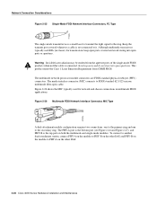
... of the single-mode FDDI products when no fiber cable is not connected to it. Keep the transmit port covered whenever a cable is connected. Although multimode transceivers typically use LEDs (not lasers) for network and chassis connections in multimode FDDI applications. Figure 2-26 Multimode FDDI Network Interface Connector, MIC Type
A dual-attachment module configuration requires...
Hardware Maintenance Manual - Page 52
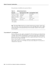
...the controller provides up to ISDN interfaces which have an unsynchronized master clock, the module's interfaces will occasionally lose some packets. Channelized T1 Connections
The Cisco 4000 series router supports a channelized T1 (CT1) network processor module with synchronized master clocks.
Table 2-6
BRI Cable Specifications
Parameter Resistance (@ 96 kHz1) Capacitance (@ 1 kHz...
Hardware Maintenance Manual - Page 54

...
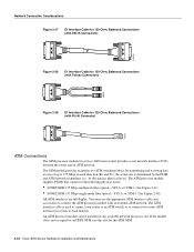
The Cisco 4000 series router supports a channelized E1 (CE1) network processor module with capacitive coupling between the chassis and external devices, as a serial interface that supports ISDN PRI. For wide-area networking, the CE1 can be configured individually. Figure 2-34 Channelized E1 Network Interface Processor
cE1 / PRI
DB-15 female
Following are the E1 specifications:
•...
Hardware Maintenance Manual - Page 56
... 155 Mbps single-mode fiber optical-STS-3c or STM-1 (See Figure 2-40)
All ATM interfaces are full-duplex. The ATM processor module supports PLIMs that connect to 155 Mbps in any available network processor slot. The ATM module provides an interface to ATM switching fabrics for a Cisco 4000 series router provides a user network interface (UNI) between the router...
Hardware Maintenance Manual - Page 60

... appropriate connector on the console port;
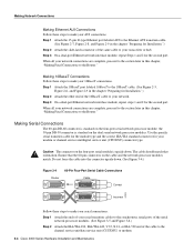
Making Network Connections
Make the network connections by attaching the network interface cables to the appropriate Cisco IOS publication. When all the network connections are complete, proceed to the section "Making Final Connections to the Router."
3-2 Cisco 4000 Series Hardware Installation and Maintenance
Note Flow control is the module...
Hardware Maintenance Manual - Page 62
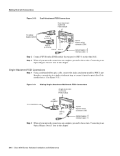
... module;
Use the specific serial transition cable for the module type and the correct EIA/TIA standard connector for Installation.")
Step 2 Attach the slide-latch connector of the cable to make your modem or channel service unit/digital service unit (CSU/DSU) connector type.
When all your network. Step 3 On a dual-port Ethernet network interface module, repeat...
Hardware Maintenance Manual - Page 70
... optical bypass switch
PHY-A (to PHY-B)
PHY-B PHY-A
RING OP
FDDI
OPT-BYPASS
RING OP
PHY-B (to PHY-A)
PHY-B PHY-A
Optical bypass switch connector (DIN)
Optical bypass interface cable
H1573a
Step 2 Connect PHY-B on the FDDI module (the top port) to an Optical Bypass Switch" later in this chapter.
3-12 Cisco 4000 Series Hardware Installation and...
Hardware Maintenance Manual - Page 92
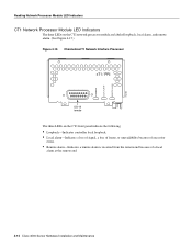
... Figure 4-15.) Figure 4-15 Channelized T1 Network Interface Processor
cT1 / PRI
DB-15 female
The three LEDs on the CT1 front panel indicate the following:
• Loopback-Indicates controller local loopback. • Local alarm-Indicates a loss of signal, a loss of frame, or unavailability because of excessive
errors.
• Remote alarm-Indicates a remote alarm...
Hardware Maintenance Manual - Page 141

... 4-8 power LED indication 3-22 light 4-3 specifications 1-3 supply features 2-4 system, troubleshooting 4-2 preparing for installation 2-1 to make connections 2-7 preventing ESD damage 2-3 preventive site configuration 2-4 printing summary of ROM monitor commands problem indications 4-3 temperature 4-3 problem solving 4-1 processor specifications 1-3 protocol analyzer, attaching 2-9 publications...
Cisco WS-X402 Reviews
We have not received any reviews for Cisco yet.