
Installation Guide
Page 31
... first member of 100 meters, to a distance of the pair (port 1) is above the second member (port 2). For example, in Figure 1-3, Figure 1-4, Figure 1-5, and Figure 1-6, ports 1 and 2 are grouped in pairs. Chapter 1 Product Overview Figure 1-5 Catalyst 3524-PWR XL Switch Front-Panel Description 30291 12...above port 4, and so on the Catalyst 3512, 3524, 3524-PWR, and 3548 XL switches are the left-most pair. The 10/100 switch ports can connect, up to any compatible network device: • 10BaseT-compatible devices such as workstations, Cisco IP Phones, and hubs through standard RJ...
... first member of 100 meters, to a distance of the pair (port 1) is above the second member (port 2). For example, in Figure 1-3, Figure 1-4, Figure 1-5, and Figure 1-6, ports 1 and 2 are grouped in pairs. Chapter 1 Product Overview Figure 1-5 Catalyst 3524-PWR XL Switch Front-Panel Description 30291 12...above port 4, and so on the Catalyst 3512, 3524, 3524-PWR, and 3548 XL switches are the left-most pair. The 10/100 switch ports can connect, up to any compatible network device: • 10BaseT-compatible devices such as workstations, Cisco IP Phones, and hubs through standard RJ...

Installation Guide
Page 33
... into a GBIC module slot on a port, the port does not provide power even if a Cisco IP Phone is connected to nine Catalyst 3500 XL switches. GBIC Module Slots The Cisco Gigabit Interface Converter (GBIC) module slots support the following modules to provide flexibility in media and distance... options: • 1000BaseSX GBIC module for fiber connections of up to 550 meters. • 1000BaseLX/...
... into a GBIC module slot on a port, the port does not provide power even if a Cisco IP Phone is connected to nine Catalyst 3500 XL switches. GBIC Module Slots The Cisco Gigabit Interface Converter (GBIC) module slots support the following modules to provide flexibility in media and distance... options: • 1000BaseSX GBIC module for fiber connections of up to 550 meters. • 1000BaseLX/...
Installation Guide
Page 35
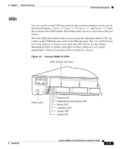
...Front-Panel Description LEDs You can use cluster management software to monitor all the switches in this section except the utilization meter (UTL) are visible on the VSM home page and Cluster Manager page. Figure 1-9 Catalyst 3508G XL LEDs GBIC module slot LEDs 18961 1 SYSTEM 2 3 RPS MODE... the Mode button that you use to monitor switch activity and its performance. The Cisco IOS Desktop Switching Software Configuration Guide describes how to use the Cluster Management Suite to monitor individual switches and how to use the switch LEDs described in this section to select one...
...Front-Panel Description LEDs You can use cluster management software to monitor all the switches in this section except the utilization meter (UTL) are visible on the VSM home page and Cluster Manager page. Figure 1-9 Catalyst 3508G XL LEDs GBIC module slot LEDs 18961 1 SYSTEM 2 3 RPS MODE... the Mode button that you use to monitor switch activity and its performance. The Cisco IOS Desktop Switching Software Configuration Guide describes how to use the Cluster Management Suite to monitor individual switches and how to use the switch LEDs described in this section to select one...

Installation Guide
Page 65
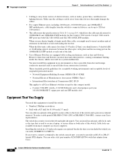
... to place the switch, be used . Class A equipment is designed for typical commercial establishments for Installation Warning This equipment is within the ranges listed in Appendix A, "Technical Specifications." 78-6456-04 Catalyst 3500 Series XL ...Hardware Installation Guide 2-7 For specific cable lengths, refer to the documents that came with the GigaStack GBIC. • Operating environment is a class A product and should be sure to observe these guidelines: • For 10/100 ports, cable lengths from the switch to connected devices are up to 100 meters...
... to place the switch, be used . Class A equipment is designed for typical commercial establishments for Installation Warning This equipment is within the ranges listed in Appendix A, "Technical Specifications." 78-6456-04 Catalyst 3500 Series XL ...Hardware Installation Guide 2-7 For specific cable lengths, refer to the documents that came with the GigaStack GBIC. • Operating environment is a class A product and should be sure to observe these guidelines: • For 10/100 ports, cable lengths from the switch to connected devices are up to 100 meters...
Installation Guide
Page 94
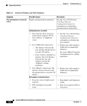
Catalyst 3500 Series XL Hardware Installation Guide 3-4 78-6456-04 Possible Cause Resolution Duplex autonegotiation mismatch. See the Cisco IOS Desktop Switching Software Configuration Guide for LED to within the recommended distances. Bad adapter in attached device. • ... 100 meters. • Reduce the cable length to a repeater, the total distance between the port and the attached device exceeds 100 meters. - Diagnosing Problems Chapter 3 Troubleshooting Table 3-2 Common Problems and Their Solutions Symptom Poor performance or excessive errors. If the switch is ...
Catalyst 3500 Series XL Hardware Installation Guide 3-4 78-6456-04 Possible Cause Resolution Duplex autonegotiation mismatch. See the Cisco IOS Desktop Switching Software Configuration Guide for LED to within the recommended distances. Bad adapter in attached device. • ... 100 meters. • Reduce the cable length to a repeater, the total distance between the port and the attached device exceeds 100 meters. - Diagnosing Problems Chapter 3 Troubleshooting Table 3-2 Common Problems and Their Solutions Symptom Poor performance or excessive errors. If the switch is ...

Hardware Installation Guide
Page 18
...ports to 52. Avoid using uninsulated exposed metal contacts, conductors, or terminals. The SFP module slots are grouped in pairs. Figure 1-10 Catalyst 3560G-48TS Switch Front Panel 119675 SYST RPS STAT DUPLX SPEED MODE 1 1X 2X 23 45 67 8 9 10 11 12 13 14 15 16 17...10/100/1000 ports to half, full, or autonegotiate on Power over Ethernet (PoE) circuits if interconnections are authorized within 328 feet (100 meters). The first member of the attached device and advertises its own capabilities. Front Panel Description Chapter 1 Product Overview The 10/100/1000 ports...
...ports to 52. Avoid using uninsulated exposed metal contacts, conductors, or terminals. The SFP module slots are grouped in pairs. Figure 1-10 Catalyst 3560G-48TS Switch Front Panel 119675 SYST RPS STAT DUPLX SPEED MODE 1 1X 2X 23 45 67 8 9 10 11 12 13 14 15 16 17...10/100/1000 ports to half, full, or autonegotiate on Power over Ethernet (PoE) circuits if interconnections are authorized within 328 feet (100 meters). The first member of the attached device and advertises its own capabilities. Front Panel Description Chapter 1 Product Overview The 10/100/1000 ports...

Hardware Installation Guide
Page 20
...for a dual-purpose uplink, see Figure 1-11). Front Panel Description Chapter 1 Product Overview Many legacy powered devices, including older Cisco IP phones and access points that first links up. Dual-Purpose Port You can configure a dual-purpose port as either a ...Catalyst series switches, you can connect only two Catalyst 3560 switches. The port LED is considered as an SFP module port. SFP Modules The switch uses Gigabit Ethernet SFP modules to the switches by a crossover cable. SFP Module Patch Cable The switch supports the SFP module patch cable (CAB-SFP-50CM=), a 0.5 meter...
...for a dual-purpose uplink, see Figure 1-11). Front Panel Description Chapter 1 Product Overview Many legacy powered devices, including older Cisco IP phones and access points that first links up. Dual-Purpose Port You can configure a dual-purpose port as either a ...Catalyst series switches, you can connect only two Catalyst 3560 switches. The port LED is considered as an SFP module port. SFP Modules The switch uses Gigabit Ethernet SFP modules to the switches by a crossover cable. SFP Module Patch Cable The switch supports the SFP module patch cable (CAB-SFP-50CM=), a 0.5 meter...

Hardware Installation Guide
Page 37
... listed in Table B-1 on page B-4, which lists the cable specifications for 1000BASE-X and 100BASE-X SFP modules for unrestricted cabling. - Catalyst 3560 switch SFP ports use shorter lengths of single-mode fiber cable, you determine where to avoid overloading the receiver. The rear-panel power connector...100/1000 ports, and 1000BASE-T SFP module ports, cable lengths from either the left side or right side of the switch should be up to 328 feet (100 meters). • The cables meet the specifications in Appendix A, "Technical Specifications." • Airflow around it might need to...
... listed in Table B-1 on page B-4, which lists the cable specifications for 1000BASE-X and 100BASE-X SFP modules for unrestricted cabling. - Catalyst 3560 switch SFP ports use shorter lengths of single-mode fiber cable, you determine where to avoid overloading the receiver. The rear-panel power connector...100/1000 ports, and 1000BASE-T SFP module ports, cable lengths from either the left side or right side of the switch should be up to 328 feet (100 meters). • The cables meet the specifications in Appendix A, "Technical Specifications." • Airflow around it might need to...
Hardware Installation Guide
Page 62
...Cisco Ethernet switches except for Installation Chapter 3 Switch Installation (8- Network Equipment Building Systems (NEBS) GR-63-CORE - International Electrotechnical Commission (IEC) IP-20 This applies to -DB-25 female DTE adapter. Make sure the cabling is safely away from the switch to 328 feet (100 meters...-X and 100BASE-X SFP modules for acceptable working environments and acceptable levels of electrical noise, such as metal flakes from Cisco. Catalyst 3560-8PC switch-8 10/100 PoE ports and 1 dual-purpose port (one 10/100/1000BASE-T copper port and one SFP module slot...
...Cisco Ethernet switches except for Installation Chapter 3 Switch Installation (8- Network Equipment Building Systems (NEBS) GR-63-CORE - International Electrotechnical Commission (IEC) IP-20 This applies to -DB-25 female DTE adapter. Make sure the cabling is safely away from the switch to 328 feet (100 meters...-X and 100BASE-X SFP modules for acceptable working environments and acceptable levels of electrical noise, such as metal flakes from Cisco. Catalyst 3560-8PC switch-8 10/100 PoE ports and 1 dual-purpose port (one 10/100/1000BASE-T copper port and one SFP module slot...

Hardware Installation Guide
Page 96
...m) 1804 feet (550 m) 1804 feet (550 m) 1804 feet (550 m) 32,810 feet (10 km) 43.4 to 62 miles (70 to 328 feet (100 meters). Cable and Adapter Specifications Appendix B Connector and Cable Specifications Cable and Adapter Specifications • SFP Module Cable Specifications, page B-4 • Two Twisted-Pair Cable Pinouts... SFP module connections. Copper 1000BASE-T SFP transceivers use standard four twisted-pair, Category 5 or greater cable at lengths up to 100 km)4 Catalyst 3560 Switch Hardware Installation Guide B-4 OL-6337-07 Each port must not exceed the required cable length.
...m) 1804 feet (550 m) 1804 feet (550 m) 1804 feet (550 m) 32,810 feet (10 km) 43.4 to 62 miles (70 to 328 feet (100 meters). Cable and Adapter Specifications Appendix B Connector and Cable Specifications Cable and Adapter Specifications • SFP Module Cable Specifications, page B-4 • Two Twisted-Pair Cable Pinouts... SFP module connections. Copper 1000BASE-T SFP transceivers use standard four twisted-pair, Category 5 or greater cable at lengths up to 100 km)4 Catalyst 3560 Switch Hardware Installation Guide B-4 OL-6337-07 Each port must not exceed the required cable length.