
Installation Guide
Page 29
...) Feature Description (continued) Management • Cisco IOS CLI through the console port or Telnet • CiscoView device-management application • Cluster Management Suite, a web-based tool for managing switch clusters or an individual switch through a single IP address • SNMP Power Redundancy • Connection for optional Cisco RPS 600 that operates on all 24 10/100 Ethernet ports • Auto-detection and control of the Catalyst 3508G XL switch (Figure 1-2) has eight 1000BaseX...
...) Feature Description (continued) Management • Cisco IOS CLI through the console port or Telnet • CiscoView device-management application • Cluster Management Suite, a web-based tool for managing switch clusters or an individual switch through a single IP address • SNMP Power Redundancy • Connection for optional Cisco RPS 600 that operates on all 24 10/100 Ethernet ports • Auto-detection and control of the Catalyst 3508G XL switch (Figure 1-2) has eight 1000BaseX...

Installation Guide
Page 33
... default. The Auto setting is inserted into a GBIC module slot on a port, the port does not provide power even if a Cisco IP Phone is connected to an AC power source for complete GBIC module information. 78-6456-04 Catalyst 3500 Series XL Hardware Installation Guide 1-9 During the power transfer, the phone might reboot or reestablish link with your Cisco IP Phone. The GigaStack GBIC supports one full-duplex link (in a point-to-point configuration...
... default. The Auto setting is inserted into a GBIC module slot on a port, the port does not provide power even if a Cisco IP Phone is connected to an AC power source for complete GBIC module information. 78-6456-04 Catalyst 3500 Series XL Hardware Installation Guide 1-9 During the power transfer, the phone might reboot or reestablish link with your Cisco IP Phone. The GigaStack GBIC supports one full-duplex link (in a point-to-point configuration...
Installation Guide
Page 49
... can manage switches from a remote location. Chapter 1 Product Overview Network Configuration Examples • Cisco IOS command-line interface (CLI) Connect a PC or terminal directly to the console port, located on the rear panel of the switch, to send and receive data. See the Cisco IOS Desktop Switching Command Reference for network bandwidth, it takes longer to access the CLI. See the CiscoView documentation for more information. Table 1-9 describes what can configure your network users. 78-6456-04 Catalyst 3500 Series XL Hardware Installation Guide...
... can manage switches from a remote location. Chapter 1 Product Overview Network Configuration Examples • Cisco IOS command-line interface (CLI) Connect a PC or terminal directly to the console port, located on the rear panel of the switch, to send and receive data. See the Cisco IOS Desktop Switching Command Reference for network bandwidth, it takes longer to access the CLI. See the CiscoView documentation for more information. Table 1-9 describes what can configure your network users. 78-6456-04 Catalyst 3500 Series XL Hardware Installation Guide...
Installation Guide
Page 83
... the console port. (See the "Connecting a PC or Terminal to the Console Port" section on page 2-23.) Note If the switch will be a cluster member, it runs a setup program that prompts you plan to use an automatic setup program to assign IP information and to create a default configuration for more information. Refer to the Cisco IOS Desktop Switching Software Configuration Guide for continued operation. If you are configuring a command switch or standalone switch...
... the console port. (See the "Connecting a PC or Terminal to the Console Port" section on page 2-23.) Note If the switch will be a cluster member, it runs a setup program that prompts you plan to use an automatic setup program to assign IP information and to create a default configuration for more information. Refer to the Cisco IOS Desktop Switching Software Configuration Guide for continued operation. If you are configuring a command switch or standalone switch...

Hardware Installation Guide
Page 18
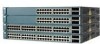
.... Catalyst 3560 Switch Hardware Installation Guide 1-8 OL-6337-07 Port 3 is above port 4, and so on. The first member of security. You can configure duplex mode to half, full, or autonegotiate on Gigabit Ethernet interfaces if the speed is 1000 Mb/s. • When set both devices support and full-duplex transmission if the attached device supports it) and configures itself accordingly. You cannot configure half-duplex mode on Gigabit Ethernet interfaces if the interface speed is set the...
.... Catalyst 3560 Switch Hardware Installation Guide 1-8 OL-6337-07 Port 3 is above port 4, and so on. The first member of security. You can configure duplex mode to half, full, or autonegotiate on Gigabit Ethernet interfaces if the speed is 1000 Mb/s. • When set both devices support and full-duplex transmission if the attached device supports it) and configures itself accordingly. You cannot configure half-duplex mode on Gigabit Ethernet interfaces if the interface speed is set the...

Hardware Installation Guide
Page 19
...)SE, the auto-MDIX feature is enabled by default. The device manager, Network Assistant, and the CLI provide PoE settings for copper Ethernet connections and configures the interfaces accordingly. The powered device might reboot or reestablish link with your IP phone or access point. For information about Cisco IP Phones and Cisco Aironet Access Points, see the switch software configuration guide. Therefore, you can connect a Cisco IP Phone or Cisco Aironet Access Point to a Catalyst 3560 PoE switch 10/100...
...)SE, the auto-MDIX feature is enabled by default. The device manager, Network Assistant, and the CLI provide PoE settings for copper Ethernet connections and configures the interfaces accordingly. The powered device might reboot or reestablish link with your IP phone or access point. For information about Cisco IP Phones and Cisco Aironet Access Points, see the switch software configuration guide. Therefore, you can connect a Cisco IP Phone or Cisco Aironet Access Point to a Catalyst 3560 PoE switch 10/100...

Hardware Installation Guide
Page 36
... electrician if you work on Power over Ethernet (PoE) circuits if interconnections are uncertain that present a shock hazard may exist on any equipment, be aware of security. Statement 1046 Warning This warning symbol means danger. Use the statement number provided at the end of each warning to de-energize the unit. Statement 1074 Catalyst 3560 Switch Hardware Installation Guide 2-4 OL-6337-07...
... electrician if you work on Power over Ethernet (PoE) circuits if interconnections are uncertain that present a shock hazard may exist on any equipment, be aware of security. Statement 1046 Warning This warning symbol means danger. Use the statement number provided at the end of each warning to de-energize the unit. Statement 1074 Catalyst 3560 Switch Hardware Installation Guide 2-4 OL-6337-07...

Hardware Installation Guide
Page 37
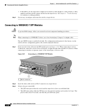
..., connect the ethernet cables only to avoid overloading the receiver. OL-6337-07 Catalyst 3560 Switch Hardware Installation Guide 2-5 Installation Guidelines When you use both GLC-GE-100XX and GLC-FE-100XX SFP modules. Access to the nearest rack metal hardware. If the switch is installed in a closed or multirack assembly, the temperature around it might damage the cables. • For copper Ethernet ports, including 10/100 ports, 10/100/1000 ports...
..., connect the ethernet cables only to avoid overloading the receiver. OL-6337-07 Catalyst 3560 Switch Hardware Installation Guide 2-5 Installation Guidelines When you use both GLC-GE-100XX and GLC-FE-100XX SFP modules. Access to the nearest rack metal hardware. If the switch is installed in a closed or multirack assembly, the temperature around it might damage the cables. • For copper Ethernet ports, including 10/100 ports, 10/100/1000 ports...

Hardware Installation Guide
Page 38
.... Catalyst 3560-8PC switch-8 10/100 PoE ports and 1 dual-purpose port (one 10/100/1000BASE-T copper port and one end of the link. • Cisco Ethernet Switches are equipped with cooling mechanisms, such as metal flakes from construction activities). and 48-Port Switches) When the fiber-optic cable span is missing or damaged, contact your configuration has an RPS, connect the switch and the RPS to rack-mount the switch...
.... Catalyst 3560-8PC switch-8 10/100 PoE ports and 1 dual-purpose port (one 10/100/1000BASE-T copper port and one end of the link. • Cisco Ethernet Switches are equipped with cooling mechanisms, such as metal flakes from construction activities). and 48-Port Switches) When the fiber-optic cable span is missing or damaged, contact your configuration has an RPS, connect the switch and the RPS to rack-mount the switch...
Hardware Installation Guide
Page 47
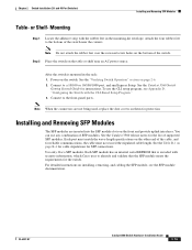
... the cable, and for instructions. You can use the CLI setup program, see the SFP module documentation. Each port must not exceed the stipulated cable length. OL-6337-07 Catalyst 3560 Switch Hardware Installation Guide 2-15 Mounting Step 1 Locate the adhesive strip with the rubber feet in the rack: 1. After the switch is encoded with the CLI-Based Setup Program." 3. and 48-Port Switches) Installing and Removing SFP Modules Table- For detailed instructions on the bottom of supported SFP modules. Note...
... the cable, and for instructions. You can use the CLI setup program, see the SFP module documentation. Each port must not exceed the stipulated cable length. OL-6337-07 Catalyst 3560 Switch Hardware Installation Guide 2-15 Mounting Step 1 Locate the adhesive strip with the rubber feet in the rack: 1. After the switch is encoded with the CLI-Based Setup Program." 3. and 48-Port Switches) Installing and Removing SFP Modules Table- For detailed instructions on the bottom of supported SFP modules. Note...
Hardware Installation Guide
Page 54
... of the cable into the SFP module port (see the switch software configuration guide or the switch command reference. When connecting to a 1000BASE-T device, use a four twisted-pair, Category 5 or higher cable. This process takes about 30 seconds, and then the port LED turns green. 2-22 Catalyst 3560 Switch Hardware Installation Guide OL-6337-07 When connecting to servers, workstations, and routers, insert a four twisted-pair, straight-through cable in the target device. See Chapter 4, "Troubleshooting," for this...
... of the cable into the SFP module port (see the switch software configuration guide or the switch command reference. When connecting to a 1000BASE-T device, use a four twisted-pair, Category 5 or higher cable. This process takes about 30 seconds, and then the port LED turns green. 2-22 Catalyst 3560 Switch Hardware Installation Guide OL-6337-07 When connecting to servers, workstations, and routers, insert a four twisted-pair, straight-through cable in the target device. See Chapter 4, "Troubleshooting," for this...
Hardware Installation Guide
Page 60
... network termination unit with integral circuit protection: 10/100/1000 Ethernet. Use the statement number provided at the end of a suitably installed ground conductor. Statement 1072 Warning No user-serviceable parts inside. Preparing for preventing accidents. A restricted access area can be familiar with local and national electrical codes. Contact the appropriate electrical inspection authority or an electrician if you work on Power over Ethernet (PoE...
... network termination unit with integral circuit protection: 10/100/1000 Ethernet. Use the statement number provided at the end of a suitably installed ground conductor. Statement 1072 Warning No user-serviceable parts inside. Preparing for preventing accidents. A restricted access area can be familiar with local and national electrical codes. Contact the appropriate electrical inspection authority or an electrician if you work on Power over Ethernet (PoE...
Hardware Installation Guide
Page 62
... connect a terminal to insert an inline optical attenuator in a system malfunction. Catalyst 3560 Switch Hardware Installation Guide 3-6 OL-6337-07 Catalyst 3560 switch SFP ports use shorter lengths of the link. • Cisco Ethernet Switches are available from the switch to install the switch: • Number-2 Phillips screwdriver • Drill with that is safely away from other particles, causing contaminant buildup inside the chassis, which lists the cable specifications for 1000BASE-X and 100BASE-X SFP modules...
... connect a terminal to insert an inline optical attenuator in a system malfunction. Catalyst 3560 Switch Hardware Installation Guide 3-6 OL-6337-07 Catalyst 3560 switch SFP ports use shorter lengths of the link. • Cisco Ethernet Switches are available from the switch to install the switch: • Number-2 Phillips screwdriver • Drill with that is safely away from other particles, causing contaminant buildup inside the chassis, which lists the cable specifications for 1000BASE-X and 100BASE-X SFP modules...
Hardware Installation Guide
Page 63
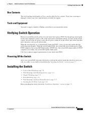
..., the system LED rapidly blinks green. To power on the switch, connect one end of the AC power cord to rack-mount the switch. When POST completes, the system LED blinks amber. OL-6337-07 Catalyst 3560 Switch Hardware Installation Guide 3-7 When the switch begins POST, the system LED slowly blinks green. Chapter 3 Switch Installation (8- If any item is missing or damaged, contact your switch fails POST. See the getting started guide for support. Call Cisco technical support representative if...
..., the system LED rapidly blinks green. To power on the switch, connect one end of the AC power cord to rack-mount the switch. When POST completes, the system LED blinks amber. OL-6337-07 Catalyst 3560 Switch Hardware Installation Guide 3-7 When the switch begins POST, the system LED slowly blinks green. Chapter 3 Switch Installation (8- If any item is missing or damaged, contact your switch fails POST. See the getting started guide for support. Call Cisco technical support representative if...
Hardware Installation Guide
Page 72
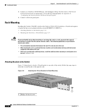
... included with the CLI-Based Setup Program." 4. Connect to the opposite side. See the Catalyst 3560 Switch Getting Started Guide for Rack-Mounting SYST STAT DPLX SPD PoE MODE CONSOLE 1x 2x 3x 4x 5x 6x 7x 8x Catalyst 3560 SERIES PoE-8 1 1 1 Phillips flat-head screws 3-16 Catalyst 3560 Switch Hardware Installation Guide OL-6337-07 Rack-Mounting Installing the Catalyst 3560-8PC switch or the Catalyst 3560 12-PC-S switch in a 19-inch rack requires a bracket...
... included with the CLI-Based Setup Program." 4. Connect to the opposite side. See the Catalyst 3560 Switch Getting Started Guide for Rack-Mounting SYST STAT DPLX SPD PoE MODE CONSOLE 1x 2x 3x 4x 5x 6x 7x 8x Catalyst 3560 SERIES PoE-8 1 1 1 Phillips flat-head screws 3-16 Catalyst 3560 Switch Hardware Installation Guide OL-6337-07 Rack-Mounting Installing the Catalyst 3560-8PC switch or the Catalyst 3560 12-PC-S switch in a 19-inch rack requires a bracket...
Hardware Installation Guide
Page 77
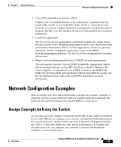
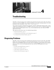
... from the command-line interface (CLI), or from an SNMP workstation. See the software configuration guide and the switch command reference on Cisco.com, or the documentation that came with your SNMP application for details. See the software configuration guide, the switch command reference guide on Cisco.com or the documentation that came with your SNMP application for troubleshooting problems: • Diagnosing Problems, page 4-1 • Clearing the Switch IP Address and Configuration, page 4-5 • Locating the Switch Serial Number, page 4-6 Diagnosing Problems The LEDs on...
... from the command-line interface (CLI), or from an SNMP workstation. See the software configuration guide and the switch command reference on Cisco.com, or the documentation that came with your SNMP application for details. See the software configuration guide, the switch command reference guide on Cisco.com or the documentation that came with your SNMP application for troubleshooting problems: • Diagnosing Problems, page 4-1 • Clearing the Switch IP Address and Configuration, page 4-5 • Locating the Switch Serial Number, page 4-6 Diagnosing Problems The LEDs on...

Hardware Installation Guide
Page 78
If POST fails, the system LED remains amber. Monitor Switch LEDs Look at the cable for marginal damage or failure. You can identify this situation because the port will have many packet errors, or the port constantly loses and regains link. If POST completes successfully, the system LED rapidly blinks green. Verify Switch Connections Review these situations: • Change the copper or fiber-optic cable with a known, good cable if necessary. • Look...
If POST fails, the system LED remains amber. Monitor Switch LEDs Look at the cable for marginal damage or failure. You can identify this situation because the port will have many packet errors, or the port constantly loses and regains link. If POST completes successfully, the system LED rapidly blinks green. Verify Switch Connections Review these situations: • Change the copper or fiber-optic cable with a known, good cable if necessary. • Look...
Hardware Installation Guide
Page 81
... duplex settings on the two ports to the factory default settings: 1. The switch LEDs begin blinking after an additional 8 seconds, and then the switch reboots. By default, the switch ports and interfaces are set to completely reconfigure the switch. Press and hold the Mode button. Continue holding down the Mode button. OL-6337-07 Catalyst 3560 Switch Hardware Installation Guide 4-5 To troubleshoot autonegotiation problems, try to configure the switch. 2. If this step and run Express Setup to manually set both sides of the connection. Clearing...
... duplex settings on the two ports to the factory default settings: 1. The switch LEDs begin blinking after an additional 8 seconds, and then the switch reboots. By default, the switch ports and interfaces are set to completely reconfigure the switch. Press and hold the Mode button. Continue holding down the Mode button. OL-6337-07 Catalyst 3560 Switch Hardware Installation Guide 4-5 To troubleshoot autonegotiation problems, try to configure the switch. 2. If this step and run Express Setup to manually set both sides of the connection. Clearing...

Hardware Installation Guide
Page 111
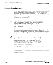
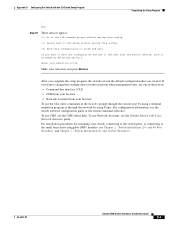
...-07 Catalyst 3560 Switch Hardware Installation Guide D-3 Appendix D Configuring the Switch with a number, is case sensitive, allows spaces, but ignores leading spaces. If POST completes successfully, the system LED rapidly blinks green. When POST completes, the system LED blinks amber. Call Cisco technical support representative if your switch, the PC or terminal displays the bootloader sequence. Would you powered on . Use ctrl-c to configure each interface on the system. Basic management setup configures only enough connectivity...
...-07 Catalyst 3560 Switch Hardware Installation Guide D-3 Appendix D Configuring the Switch with a number, is case sensitive, allows spaces, but ignores leading spaces. If POST completes successfully, the system LED rapidly blinks green. When POST completes, the system LED blinks amber. Call Cisco technical support representative if your switch, the PC or terminal displays the bootloader sequence. Would you powered on . Use ctrl-c to configure each interface on the system. Basic management setup configures only enough connectivity...
Hardware Installation Guide
Page 113
...-07 Catalyst 3560 Switch Hardware Installation Guide D-5 To use it the next time the switch reboots, save the configuration and use Network Assistant, see Chapter 2, "Switch Installation (24- and 48-Port Switches)" and Chapter 3, "Switch Installation (8- and 12-Port Switches)." If you created. After you complete the setup program, the switch can run the default configuration that you want to save it in NVRAM by using a terminal emulation program or through the console port by using Telnet. To use the CLI, enter commands at the Switch> prompt...
...-07 Catalyst 3560 Switch Hardware Installation Guide D-5 To use it the next time the switch reboots, save the configuration and use Network Assistant, see Chapter 2, "Switch Installation (24- and 48-Port Switches)" and Chapter 3, "Switch Installation (8- and 12-Port Switches)." If you created. After you complete the setup program, the switch can run the default configuration that you want to save it in NVRAM by using a terminal emulation program or through the console port by using Telnet. To use the CLI, enter commands at the Switch> prompt...


