
Installation Guide
Page 6
... Up the Switch 2-1 Preparing for Using the Switch 1-25 Small- Contents 2 C H A P T E R LEDs 1-11 System LED 1-14 RPS LED 1-15 Port LEDs and Modes 1-16 Rear-Panel Description 1-21 Power Connectors 1-22 Internal Power Supply Connector 1-23 Cisco RPS Connector 1-23 Console Port 1-24 Management Options 1-24 Network Configuration Examples 1-25 Design Concepts for Installation 2-2 Warnings 2-2 EMC Regulatory Statements 2-5 U.S.A. 2-5 Taiwan 2-5 Japan 2-6 Korea 2-6 Hungary 2-7 Installation Guidelines 2-7 Verifying Package Contents 2-8 Catalyst 3500 Series XL Hardware Installation Guide vi 78...
... Up the Switch 2-1 Preparing for Using the Switch 1-25 Small- Contents 2 C H A P T E R LEDs 1-11 System LED 1-14 RPS LED 1-15 Port LEDs and Modes 1-16 Rear-Panel Description 1-21 Power Connectors 1-22 Internal Power Supply Connector 1-23 Cisco RPS Connector 1-23 Console Port 1-24 Management Options 1-24 Network Configuration Examples 1-25 Design Concepts for Installation 2-2 Warnings 2-2 EMC Regulatory Statements 2-5 U.S.A. 2-5 Taiwan 2-5 Japan 2-6 Korea 2-6 Hungary 2-7 Installation Guidelines 2-7 Verifying Package Contents 2-8 Catalyst 3500 Series XL Hardware Installation Guide vi 78...

Installation Guide
Page 12
... functional overview of how the switch could be used to connect to set up the switch initial configuration. Chapter 2, "Installing and Starting Up the Switch," contains the procedures for the switches and the regulatory agency approvals. Examples of the switch. Appendix B, "Connector and Cable Specifications," describes the connectors, cables, and adapters that might arise when you are installing the switch. Catalyst 3500 Series XL Hardware Installation Guide xii 78-6456-04 It...
... functional overview of how the switch could be used to connect to set up the switch initial configuration. Chapter 2, "Installing and Starting Up the Switch," contains the procedures for the switches and the regulatory agency approvals. Examples of the switch. Appendix B, "Connector and Cable Specifications," describes the connectors, cables, and adapters that might arise when you are installing the switch. Catalyst 3500 Series XL Hardware Installation Guide xii 78-6456-04 It...

Installation Guide
Page 27
... Catalyst 3508G XL switch) Management • Cisco IOS command-line interface (CLI) through the console port or Telnet • CiscoView device-management application • Cluster Management Suite, a web-based tool for managing switch clusters or an individual switch through a single IP address • Simple Network Management Protocol (SNMP) Power Redundancy • Connection for optional Cisco 600W Redundant Power System (RPS) that operates on any port • Support for command switch redundancy • Support for up to 250 port-based virtual LANs (VLANs...
... Catalyst 3508G XL switch) Management • Cisco IOS command-line interface (CLI) through the console port or Telnet • CiscoView device-management application • Cluster Management Suite, a web-based tool for managing switch clusters or an individual switch through a single IP address • Simple Network Management Protocol (SNMP) Power Redundancy • Connection for optional Cisco 600W Redundant Power System (RPS) that operates on any port • Support for command switch redundancy • Support for up to 250 port-based virtual LANs (VLANs...

Installation Guide
Page 28
... VLAN ID (VVID) • High-speed EtherChannel connections between switches and servers • 8192 MAC addresses • IEEE 802.1p capable • CGMP to limit the flooding of IP multicast traffic • Broadcast storm control to prevent performance degradation from broadcast storms • SPAN port monitoring on any port • Support for command switch redundancy • Support for Cisco GBIC modules - GigaStack GBIC - 1000BaseSX GBIC module - 1000BaseLX/LH GBIC module - 1000BaseZX GBIC module Catalyst 3500 Series XL Hardware Installation Guide...
... VLAN ID (VVID) • High-speed EtherChannel connections between switches and servers • 8192 MAC addresses • IEEE 802.1p capable • CGMP to limit the flooding of IP multicast traffic • Broadcast storm control to prevent performance degradation from broadcast storms • SPAN port monitoring on any port • Support for command switch redundancy • Support for Cisco GBIC modules - GigaStack GBIC - 1000BaseSX GBIC module - 1000BaseLX/LH GBIC module - 1000BaseZX GBIC module Catalyst 3500 Series XL Hardware Installation Guide...

Installation Guide
Page 29
... Description (continued) Management • Cisco IOS CLI through the console port or Telnet • CiscoView device-management application • Cluster Management Suite, a web-based tool for managing switch clusters or an individual switch through a single IP address • SNMP Power Redundancy • Connection for optional Cisco RPS 600 that operates on AC input and supplies DC output to the Catalyst 3512, 3524, and 3548 XL switches • Connection for fan-fault and...
... Description (continued) Management • Cisco IOS CLI through the console port or Telnet • CiscoView device-management application • Cluster Management Suite, a web-based tool for managing switch clusters or an individual switch through a single IP address • SNMP Power Redundancy • Connection for optional Cisco RPS 600 that operates on AC input and supplies DC output to the Catalyst 3512, 3524, and 3548 XL switches • Connection for fan-fault and...

Installation Guide
Page 32
... connected On a per -port priority override. When set to the Cisco IOS Desktop Switching Software Configuration Guide for more information about these cables do not work for inline power on a port, the port Catalyst 3500 Series XL Hardware Installation Guide 1-8 78-6456-04 Refer to operate in Appendix B, "Connector and Cable Specifications." The Catalyst 3548 and 3524-PWR XL switches also support per -port basis, you select the Auto setting for ports operating at 100 Mbps. Cisco IP Phones-connected...
... connected On a per -port priority override. When set to the Cisco IOS Desktop Switching Software Configuration Guide for more information about these cables do not work for inline power on a port, the port Catalyst 3500 Series XL Hardware Installation Guide 1-8 78-6456-04 Refer to operate in Appendix B, "Connector and Cable Specifications." The Catalyst 3548 and 3524-PWR XL switches also support per -port basis, you select the Auto setting for ports operating at 100 Mbps. Cisco IP Phones-connected...

Installation Guide
Page 33
The Auto setting is 1 meter. During the power transfer, the phone might reboot or reestablish link with your GBIC module for complete GBIC module information. 78-6456-04 Catalyst 3500 Series XL Hardware Installation Guide 1-9 The GigaStack GBIC supports one full-duplex link (in a point-to-point configuration) or up to nine half-duplex links (in media and distance options: • 1000BaseSX GBIC module for fiber connections of up to 550 meters...
The Auto setting is 1 meter. During the power transfer, the phone might reboot or reestablish link with your GBIC module for complete GBIC module information. 78-6456-04 Catalyst 3500 Series XL Hardware Installation Guide 1-9 The GigaStack GBIC supports one full-duplex link (in a point-to-point configuration) or up to nine half-duplex links (in media and distance options: • 1000BaseSX GBIC module for fiber connections of up to 550 meters...

Installation Guide
Page 39
...) supports the Catalyst 3524-PWR XL switch. 78-6456-04 Catalyst 3500 Series XL Hardware Installation Guide 1-15 RPS and the switch AC power supply are using power from the RPS. Note If you are both powered on the RPS could have failed. Table 1-4 and Table 1-5 list the LED colors and their meanings. The LEDs display correctly for the Catalyst 3508, 3512, 3524, and 3548 XL Switches Color Off Solid green Blinking green Amber RPS Status RPS...
...) supports the Catalyst 3524-PWR XL switch. 78-6456-04 Catalyst 3500 Series XL Hardware Installation Guide 1-15 RPS and the switch AC power supply are using power from the RPS. Note If you are both powered on the RPS could have failed. Table 1-4 and Table 1-5 list the LED colors and their meanings. The LEDs display correctly for the Catalyst 3508, 3512, 3524, and 3548 XL Switches Color Off Solid green Blinking green Amber RPS Status RPS...

Installation Guide
Page 40
... the default mode. When you change the port mode in use by the switch. 1-16 Catalyst 3500 Series XL Hardware Installation Guide 78-6456-04 The port modes (Table 1-6) determine the type of the switch is down , or a fan on the RPS. Table 1-7 and Table 1-8 explain how to the Cisco Redundant Power System 300 Hardware Installation Guide. Table 1-6 Port Mode LEDs Mode LED STAT UTL Port Mode Port status Switch utilization Description The port status. One of the port LED colors also changes. Internal power supply of information displayed through the port LEDs. RPS is lost.
... the default mode. When you change the port mode in use by the switch. 1-16 Catalyst 3500 Series XL Hardware Installation Guide 78-6456-04 The port modes (Table 1-6) determine the type of the switch is down , or a fan on the RPS. Table 1-7 and Table 1-8 explain how to the Cisco Redundant Power System 300 Hardware Installation Guide. Table 1-6 Port Mode LEDs Mode LED STAT UTL Port Mode Port status Switch utilization Description The port status. One of the port LED colors also changes. Internal power supply of information displayed through the port LEDs. RPS is lost.

Installation Guide
Page 41
... duplex. Port was disabled by management or an address violation or was blocked by Spanning Tree Protocol (STP). Port is transmitting or receiving data. Port is using less than 50 percent of its total bandwidth. If all port LEDs are monitored for details. Chapter 1 Product Overview Front-Panel Description Table 1-6 Port Mode LEDs (continued) Mode LED DUPLX SPEED LINE PWR Port Mode Port duplex mode Port speed Port inline power Description The port duplex mode: full duplex or half duplex. The inline power status: on a logarithmic scale. If the LED...
... duplex. Port was disabled by management or an address violation or was blocked by Spanning Tree Protocol (STP). Port is transmitting or receiving data. Port is using less than 50 percent of its total bandwidth. If all port LEDs are monitored for details. Chapter 1 Product Overview Front-Panel Description Table 1-6 Port Mode LEDs (continued) Mode LED DUPLX SPEED LINE PWR Port Mode Port duplex mode Port speed Port inline power Description The port duplex mode: full duplex or half duplex. The inline power status: on a logarithmic scale. If the LED...
Installation Guide
Page 49
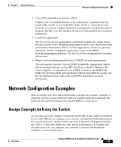
... Fast Ethernet and Gigabit Ethernet connections. Design Concepts for more information. • CiscoView application The CiscoView device-management application displays the switch image that you can manage switches from a remote location. See the CiscoView documentation for Using the Switch As your network users. 78-6456-04 Catalyst 3500 Series XL Hardware Installation Guide 1-25 Network Configuration Examples This section provides network configuration concepts and includes examples of an SNMP network-management platform. The switch supports a comprehensive set configuration...
... Fast Ethernet and Gigabit Ethernet connections. Design Concepts for more information. • CiscoView application The CiscoView device-management application displays the switch image that you can manage switches from a remote location. See the CiscoView documentation for Using the Switch As your network users. 78-6456-04 Catalyst 3500 Series XL Hardware Installation Guide 1-25 Network Configuration Examples This section provides network configuration concepts and includes examples of an SNMP network-management platform. The switch supports a comprehensive set configuration...

Installation Guide
Page 50
... configuration examples for IP telephony • Use quality of service (QoS) to prioritize applications such as either high or low priority based on a single network segment and a growing number of users accessing the Internet • Create smaller network segments so that fewer users share the bandwidth, and place the network resources in the stack fails, connect the bottom switch to the top switch to create a GigaStack loopback. 1-26 Catalyst 3500 Series...
... configuration examples for IP telephony • Use quality of service (QoS) to prioritize applications such as either high or low priority based on a single network segment and a growing number of users accessing the Internet • Create smaller network segments so that fewer users share the bandwidth, and place the network resources in the stack fails, connect the bottom switch to the top switch to create a GigaStack loopback. 1-26 Catalyst 3500 Series...

Installation Guide
Page 55
... monitoring and controlling the network. Users with RJ-45 connectors-to the 10/100 inline-power ports on the Catalyst 3524-PWR XL switches and to the 10/100 ports on WAN access. You can manage a cluster through , twisted-pair cable with workstations running Cisco CallManager software, a Dynamic Host Configuration Protocol (DHCP)/Bootstrap Protocol (BOOTP) server, or an IPTV multicast server). 78-6456-04 Catalyst 3500 Series XL Hardware Installation Guide 1-31 These multiservice switch ports...
... monitoring and controlling the network. Users with RJ-45 connectors-to the 10/100 inline-power ports on the Catalyst 3524-PWR XL switches and to the 10/100 ports on WAN access. You can manage a cluster through , twisted-pair cable with workstations running Cisco CallManager software, a Dynamic Host Configuration Protocol (DHCP)/Bootstrap Protocol (BOOTP) server, or an IPTV multicast server). 78-6456-04 Catalyst 3500 Series XL Hardware Installation Guide 1-31 These multiservice switch ports...
Installation Guide
Page 59
...; Installation procedures • Power-on self-test (POST) that ensures proper operation. CH A P T E R 2 Installing and Starting Up the Switch This chapter describes how to install and start up your Catalyst 3500 XL switches and to interpret the power-on procedures • Connection procedures • Set up procedures for initial configuration • Default configuration settings • Where to go next 78-6456-04 Catalyst 3500 Series XL Hardware Installation Guide...
...; Installation procedures • Power-on self-test (POST) that ensures proper operation. CH A P T E R 2 Installing and Starting Up the Switch This chapter describes how to install and start up your Catalyst 3500 XL switches and to interpret the power-on procedures • Connection procedures • Set up procedures for initial configuration • Default configuration settings • Where to go next 78-6456-04 Catalyst 3500 Series XL Hardware Installation Guide...

Installation Guide
Page 81
... between the switch and your PC- For console port and adapter pinout information, see the "Cable and Adapter Specifications" section on the GigaStack GBIC connections and configuration scenarios, see the Catalyst GigaStack Gigabit Interface Converter Hardware Installation Guide. or terminal-emulation software is configured to the switch console port. Connecting a PC or Terminal to the Console Port Use the supplied rollover cable and DB-9 adapter to connect a PC to communicate with the switch via hardware flow control. Follow these console port default characteristics: •...
... between the switch and your PC- For console port and adapter pinout information, see the "Cable and Adapter Specifications" section on the GigaStack GBIC connections and configuration scenarios, see the Catalyst GigaStack Gigabit Interface Converter Hardware Installation Guide. or terminal-emulation software is configured to the switch console port. Connecting a PC or Terminal to the Console Port Use the supplied rollover cable and DB-9 adapter to connect a PC to communicate with the switch via hardware flow control. Follow these console port default characteristics: •...
Installation Guide
Page 83
Refer to create a default configuration for continued operation. Chapter 2 Installing and Starting Up the Switch Assigning Switch Information Using the Setup Program You can use the Cluster Management Suite or the command-line interface (CLI) to customize your system administrator: Switch IP address Subnet mask (netmask 78-6456-04 Catalyst 3500 Series XL Hardware Installation Guide 2-25 To run the setup program, access the switch from your configuration. This information also is required if you can use the...
Refer to create a default configuration for continued operation. Chapter 2 Installing and Starting Up the Switch Assigning Switch Information Using the Setup Program You can use the Cluster Management Suite or the command-line interface (CLI) to customize your system administrator: Switch IP address Subnet mask (netmask 78-6456-04 Catalyst 3500 Series XL Hardware Installation Guide 2-25 To run the setup program, access the switch from your configuration. This information also is required if you can use the...
Installation Guide
Page 87
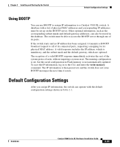
... default configuration settings shown in Table 2-1. 78-6456-04 Catalyst 3500 Series XL Hardware Installation Guide 2-29 The reception of a valid BOOTP response immediately activates the rest of its physical MAC address. The switch must be able to the CLI, and enter the write memory command. To save the IP information, log in Flash memory is mandatory, and the subnet mask and the default gateway, which is not automatically updated...
... default configuration settings shown in Table 2-1. 78-6456-04 Catalyst 3500 Series XL Hardware Installation Guide 2-29 The reception of a valid BOOTP response immediately activates the rest of its physical MAC address. The switch must be able to the CLI, and enter the write memory command. To save the IP information, log in Flash memory is mandatory, and the subnet mask and the default gateway, which is not automatically updated...
Installation Guide
Page 89
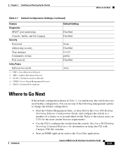
...CGMP = Cisco Group Management Protocol 5. Disabled. Refer to Go Next Table 2-1 Default Configuration Settings (continued) Feature Diagnostics SPAN5 port monitoring Console, buffer, and file logging Security Password Addressing security Trap manager Community strings Port security Inline Power Inline power mode 1. Chapter 2 Installing and Starting Up the Switch Where to the release notes on CCO for information on using the CLI with Catalyst 3500 XL switches. • Start an SNMP application such as an individual switch. VLAN = Virtual Local Area Network 4. Auto. ARP...
...CGMP = Cisco Group Management Protocol 5. Disabled. Refer to Go Next Table 2-1 Default Configuration Settings (continued) Feature Diagnostics SPAN5 port monitoring Console, buffer, and file logging Security Password Addressing security Trap manager Community strings Port security Inline Power Inline power mode 1. Chapter 2 Installing and Starting Up the Switch Where to the release notes on CCO for information on using the CLI with Catalyst 3500 XL switches. • Start an SNMP application such as an individual switch. VLAN = Virtual Local Area Network 4. Auto. ARP...

Installation Guide
Page 91
... the browser interface, from the command-line interface (CLI), or from an Simple Network Management Protocol (SNMP) workstation. This chapter describes the following topics for details. See the Cisco IOS Desktop Switching Software Configuration Guide, the Cisco IOS Desktop Switching Command Reference (online only), or the documentation that came with your SNMP application for troubleshooting problems: • Understanding POST results • Diagnosing problems 78-6456-04 Catalyst 3500 Series XL Hardware Installation Guide 3-1 CH A P T E R 3 Troubleshooting The LEDs on the...
... the browser interface, from the command-line interface (CLI), or from an Simple Network Management Protocol (SNMP) workstation. This chapter describes the following topics for details. See the Cisco IOS Desktop Switching Software Configuration Guide, the Cisco IOS Desktop Switching Command Reference (online only), or the documentation that came with your SNMP application for troubleshooting problems: • Understanding POST results • Diagnosing problems 78-6456-04 Catalyst 3500 Series XL Hardware Installation Guide 3-1 CH A P T E R 3 Troubleshooting The LEDs on the...

Installation Guide
Page 96
... XL switch can operate normally with one failed fan. Catalyst 3500 Series XL Hardware Installation Guide 3-6 78-6456-04 If a multiple-fan failure is causing the switch to overheat, replace the switch. • Use the show env command to power on the Catalyst 3524-PWR XL. Cisco IP Phone fails to check if an overtemperature condition exists. Place the switch in an environment that is overheating. • Nonfatal or fatal POST error...
... XL switch can operate normally with one failed fan. Catalyst 3500 Series XL Hardware Installation Guide 3-6 78-6456-04 If a multiple-fan failure is causing the switch to overheat, replace the switch. • Use the show env command to power on the Catalyst 3524-PWR XL. Cisco IP Phone fails to check if an overtemperature condition exists. Place the switch in an environment that is overheating. • Nonfatal or fatal POST error...


