
Hardware Installation Guide
Page 23
...You use Category 5 or higher cable with LC connectors to connect to establish fiber-optic connections. The dual front ends are field-replaceable, providing the uplink interfaces when you insert an SFP module. For more information about cabling requirements, see Appendix B, "Connector and Cable... information about configuring speed and duplex settings for a dual-purpose uplink, see your SFP module documentation or the release notes for your Cisco representative. (See Figure 1-22.) OL-7075-09 Catalyst 2960 Switch Hardware Installation Guide 1-13 Through a 10/100/1000 port from ...
...You use Category 5 or higher cable with LC connectors to connect to establish fiber-optic connections. The dual front ends are field-replaceable, providing the uplink interfaces when you insert an SFP module. For more information about cabling requirements, see Appendix B, "Connector and Cable... information about configuring speed and duplex settings for a dual-purpose uplink, see your SFP module documentation or the release notes for your Cisco representative. (See Figure 1-22.) OL-7075-09 Catalyst 2960 Switch Hardware Installation Guide 1-13 Through a 10/100/1000 port from ...
Hardware Installation Guide
Page 35
... unit. Statement 1040. Statement 1044 OL-7075-09 Catalyst 2960 Switch Hardware Installation Guide 2-3 Chapter 2 Switch Installation (24- All connections must be allowed to install, replace, or service this unit in a rack, you are provided to ensure that suitable grounding is intended for Installation Warning To prevent bodily injury when mounting...
... unit. Statement 1040. Statement 1044 OL-7075-09 Catalyst 2960 Switch Hardware Installation Guide 2-3 Chapter 2 Switch Installation (24- All connections must be allowed to install, replace, or service this unit in a rack, you are provided to ensure that suitable grounding is intended for Installation Warning To prevent bodily injury when mounting...

Hardware Installation Guide
Page 36
... (8-Port Switches)." Preparing for acceptable working environments and acceptable levels of the hazard. and 48-Port Switches) Warning When installing or replacing the unit, the ground connection must install this equipment in a system malfunction. You must always be no longer than 328 feet ... local and national electrical codes. Installation Guidelines This section does not apply to all Catalyst 2960 switches except for Particulate Matter Cisco Ethernet switches are made aware of suspended particulate matter: • Network Equipment Building Systems (NEBS) GR-63-CORE •...
... (8-Port Switches)." Preparing for acceptable working environments and acceptable levels of the hazard. and 48-Port Switches) Warning When installing or replacing the unit, the ground connection must install this equipment in a system malfunction. You must always be no longer than 328 feet ... local and national electrical codes. Installation Guidelines This section does not apply to all Catalyst 2960 switches except for Particulate Matter Cisco Ethernet switches are made aware of suspended particulate matter: • Network Equipment Building Systems (NEBS) GR-63-CORE •...
Hardware Installation Guide
Page 46
.../100/1000 ports configure themselves to a 10/100 or 10/100/1000 port, and run Express Setup. Note When the connectors are not being used, replace the dust covers on the bottom of attached devices. and 48-Port Switches) After the switch is mounted on the table, do not support autonegotiation...
.../100/1000 ports configure themselves to a 10/100 or 10/100/1000 port, and run Express Setup. Note When the connectors are not being used, replace the dust covers on the bottom of attached devices. and 48-Port Switches) After the switch is mounted on the table, do not support autonegotiation...

Hardware Installation Guide
Page 47
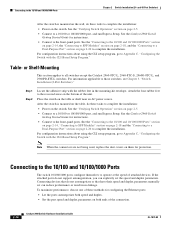
... of the Catalyst 2960 switches. You can take up to connect each device. Step 1 When connecting to workstations, servers, routers, and Cisco IP Phones, connect a straight-through 3 to 30 seconds, and then the port LED turns green. For configuration information for solutions to ... twisted four-pair, Category 5 or higher cable. Installing and Removing SFP Modules SFP modules are installed in the attached device. These field-replaceable modules provide the uplink optical interfaces, laser send (TX) and laser receive (RX). Repeat Steps 1 through cable to an RJ-45 connector...
... of the Catalyst 2960 switches. You can take up to connect each device. Step 1 When connecting to workstations, servers, routers, and Cisco IP Phones, connect a straight-through 3 to 30 seconds, and then the port LED turns green. For configuration information for solutions to ... twisted four-pair, Category 5 or higher cable. Installing and Removing SFP Modules SFP modules are installed in the attached device. These field-replaceable modules provide the uplink optical interfaces, laser send (TX) and laser receive (RX). Repeat Steps 1 through cable to an RJ-45 connector...
Hardware Installation Guide
Page 48
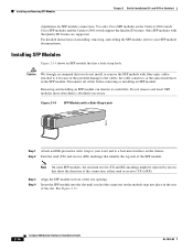
... is absolutely necessary. Insert the SFP module into place in front of the SFP module. and 48-Port Switches) stipulations for SFP module connections. Cisco SFP modules and the Catalyst 2960 switch support the Quality ID feature. Caution We strongly recommend that identify the top side of the slot opening... instructions on the chassis. Note On some SFP modules, the send and receive (TX and RX) markings might be replaced by arrows that has a bale-clasp latch. Use only Cisco SFP modules on the module snap into the slot until you do not install or remove the SFP module with the...
... is absolutely necessary. Insert the SFP module into place in front of the SFP module. and 48-Port Switches) stipulations for SFP module connections. Cisco SFP modules and the Catalyst 2960 switch support the Quality ID feature. Caution We strongly recommend that identify the top side of the slot opening... instructions on the chassis. Note On some SFP modules, the send and receive (TX and RX) markings might be replaced by arrows that has a bale-clasp latch. Use only Cisco SFP modules on the module snap into the slot until you do not install or remove the SFP module with the...

Hardware Installation Guide
Page 57
... equipment in Appendix A, "Technical Specifications." • Airflow around the unit does not exceed 113°F (45°C). Statement 1040. Statement 1044 Warning When installing or replacing the unit, the ground connection must be within the ranges listed in the absence of clearance around the ventilation openings. • Temperature around the switch...
... equipment in Appendix A, "Technical Specifications." • Airflow around the unit does not exceed 113°F (45°C). Statement 1040. Statement 1044 Warning When installing or replacing the unit, the ground connection must be within the ranges listed in the absence of clearance around the ventilation openings. • Temperature around the switch...

Hardware Installation Guide
Page 75
... SFP module. Sometimes a cable appears to show interfaces privileged EXEC command to function at a marginal level. This encoding provides a way for Cisco to the correct ports. • Verify that both sides have link. A single broken wire or one shutdown port can cause one side to... Use the show link, but is encoded with a known, good module. Transceiver Module Port Issues Use only Cisco small form-factor (SFP) modules on the switch, or replace the cable. Chapter 4 Troubleshooting Diagnosing Problems Ethernet and Fiber Cables Make sure that you have the correct cable ...
... SFP module. Sometimes a cable appears to show interfaces privileged EXEC command to function at a marginal level. This encoding provides a way for Cisco to the correct ports. • Verify that both sides have link. A single broken wire or one shutdown port can cause one side to... Use the show link, but is encoded with a known, good module. Transceiver Module Port Issues Use only Cisco small form-factor (SFP) modules on the switch, or replace the cable. Chapter 4 Troubleshooting Diagnosing Problems Ethernet and Fiber Cables Make sure that you have the correct cable ...

