Hardware Installation Guide
Page 4
... Matter 2-4 Installation Guidelines 2-4 Box Contents 2-5 Tools and Equipment 2-5 Verifying Switch Operation 2-5 Installing the Switch 2-6 Rack-Mounting 2-6 Removing Screws from the Switch 2-7 Attaching Brackets to the Catalyst 2960 Switch 2-7 Mounting the Switch in a Rack 2-10 Attaching the Cable Guide 2-11 Wall-Mounting 2-11 Attaching the Brackets to Go Next 2-21 Switch Installation (8-Port Switches) 3-1 Preparing for...
... Matter 2-4 Installation Guidelines 2-4 Box Contents 2-5 Tools and Equipment 2-5 Verifying Switch Operation 2-5 Installing the Switch 2-6 Rack-Mounting 2-6 Removing Screws from the Switch 2-7 Attaching Brackets to the Catalyst 2960 Switch 2-7 Mounting the Switch in a Rack 2-10 Attaching the Cable Guide 2-11 Wall-Mounting 2-11 Attaching the Brackets to Go Next 2-21 Switch Installation (8-Port Switches) 3-1 Preparing for...

Hardware Installation Guide
Page 5
... the Switch Serial Number 4-6 Technical Specifications A-1 Connector and Cable Specifications B-1 Connector Specifications B-1 10/100/1000 Ports B-1 Connecting to 10BASE-T- or Shelf-Mounting (with Mounting Screws) 3-8 Wall-Mounting (with Mounting Screws) 3-11 Magnet Mounting 3-14 Rack-Mounting 3-15 Attaching Brackets to 1000BASE-T Devices B-2 SFP Module Ports B-3 Dual-Purpose Ports B-3 Catalyst 2960 Switch Hardware Installation Guide v Contents 4 C H A P T E R A A P P E N D I X B A P P E N D I X OL-7075...
... the Switch Serial Number 4-6 Technical Specifications A-1 Connector and Cable Specifications B-1 Connector Specifications B-1 10/100/1000 Ports B-1 Connecting to 10BASE-T- or Shelf-Mounting (with Mounting Screws) 3-8 Wall-Mounting (with Mounting Screws) 3-11 Magnet Mounting 3-14 Rack-Mounting 3-15 Attaching Brackets to 1000BASE-T Devices B-2 SFP Module Ports B-3 Dual-Purpose Ports B-3 Catalyst 2960 Switch Hardware Installation Guide v Contents 4 C H A P T E R A A P P E N D I X B A P P E N D I X OL-7075...
Hardware Installation Guide
Page 35
...combination must be accessed only through an approved network termination unit with stabilizing devices, install the stabilizers before mounting or servicing the unit in a partially filled rack, load the rack from the bottom to ensure your safety: • This unit should be grounded. Warning For connections outside...precautions to all times, because it is the only unit in the rack. • When mounting this unit in a rack, you are provided to the top with the heaviest component at the bottom of the rack if it serves as the main disconnecting device. Statement 1024 Warning ...
...combination must be accessed only through an approved network termination unit with stabilizing devices, install the stabilizers before mounting or servicing the unit in a partially filled rack, load the rack from the bottom to ensure your safety: • This unit should be grounded. Warning For connections outside...precautions to all times, because it is the only unit in the rack. • When mounting this unit in a rack, you are provided to the top with the heaviest component at the bottom of the rack if it serves as the main disconnecting device. Statement 1024 Warning ...

Hardware Installation Guide
Page 37
... an inline optical attenuator in the link to the switch, put the RPS in Appendix A, "Technical Specifications." • Clearance to rack-mount the switch. Verifying Switch Operation Before you install the switch in a closed or multirack assembly, the temperature around the unit does not... avoid overloading the receiver. Access to active mode during normal operation. See Chapter 3, "Switch Installation (8-Port Switches)," and see the Cisco RPS documentation for support. Make sure the cabling is missing or damaged, contact your configuration has an RPS, connect the switch and ...
... an inline optical attenuator in the link to the switch, put the RPS in Appendix A, "Technical Specifications." • Clearance to rack-mount the switch. Verifying Switch Operation Before you install the switch in a closed or multirack assembly, the temperature around the unit does not... avoid overloading the receiver. Access to active mode during normal operation. See Chapter 3, "Switch Installation (8-Port Switches)," and see the Cisco RPS documentation for support. Make sure the cabling is missing or damaged, contact your configuration has an RPS, connect the switch and ...

Hardware Installation Guide
Page 38
... remains green. POST failures are provided to ensure your switch fails POST. This section describes these installation procedures: • Rack-Mounting, page 2-6 • Wall-Mounting, page 2-11 • Table- however, the instructions apply to ensure that the switch functions properly. If a switch ...Switches)." Call Cisco technical support representative if your safety: • This unit should be mounted at the bottom of the rack if it begins the POST, a series of the rack. • If the rack is the only unit in the rack. • When mounting this unit in a rack, you ...
... remains green. POST failures are provided to ensure your switch fails POST. This section describes these installation procedures: • Rack-Mounting, page 2-6 • Wall-Mounting, page 2-11 • Table- however, the instructions apply to ensure that the switch functions properly. If a switch ...Switches)." Call Cisco technical support representative if your safety: • This unit should be mounted at the bottom of the rack if it begins the POST, a series of the rack. • If the rack is the only unit in the rack. • When mounting this unit in a rack, you ...

Hardware Installation Guide
Page 39
and 48-Port Switches) Installing the Switch To install the switch in a 19-inch or 24-inch rack (24-inch racks require optional mounting hardware), follow the instructions described in these sections: • Removing Screws from Cisco by using part number RCKMNT-1RU=. Figure 2-1 Removing Screws from the Switch If you plan to remove the...
and 48-Port Switches) Installing the Switch To install the switch in a 19-inch or 24-inch rack (24-inch racks require optional mounting hardware), follow the instructions described in these sections: • Removing Screws from Cisco by using part number RCKMNT-1RU=. Figure 2-1 Removing Screws from the Switch If you plan to remove the...
Hardware Installation Guide
Page 42
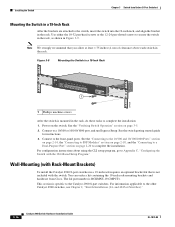
... SYST RPS STAT DUPLX SPEED MODE 1 1 Phillips machine screws After the switch is mounted in the rack, do these tasks to complete the installation: • Power on page 2-20 to a Dual-Purpose Port" section on the switch. See the Catalyst 2960 Switch ... the front-panel ports. Installing the Switch Chapter 2 Switch Installation (24- See the "Verifying Switch Operation" section on page 2-5. • Connect to the rack, as shown in a Rack After the brackets are attached to the switch, use the four supplied number-12 Phillips machine screws to securely attach the brackets to a 10...
... SYST RPS STAT DUPLX SPEED MODE 1 1 Phillips machine screws After the switch is mounted in the rack, do these tasks to complete the installation: • Power on page 2-20 to a Dual-Purpose Port" section on the switch. See the Catalyst 2960 Switch ... the front-panel ports. Installing the Switch Chapter 2 Switch Installation (24- See the "Verifying Switch Operation" section on page 2-5. • Connect to the rack, as shown in a Rack After the brackets are attached to the switch, use the four supplied number-12 Phillips machine screws to securely attach the brackets to a 10...

Hardware Installation Guide
Page 43
...cable guide to the left or right bracket. For information applicable to the Catalyst 2960 8-port switches. Use the supplied black screw shown in the rack. To install the switch on a wall, follow the instructions in these sections: • Attaching the Brackets to the Switch for Wall... Switch on the Catalyst 2960 Switch 1 SYST RPS STAT DUPLX SPEED MODE 204619 1 Cable guide screw Wall-Mounting This section does not apply to those switches, see Chapter 3, "Switch Installation (8-Port Switches)." Chapter 2 Switch Installation (24- Figure 2-9 Attaching the Cable Guide on a Wall,...
...cable guide to the left or right bracket. For information applicable to the Catalyst 2960 8-port switches. Use the supplied black screw shown in the rack. To install the switch on a wall, follow the instructions in these sections: • Attaching the Brackets to the Switch for Wall... Switch on the Catalyst 2960 Switch 1 SYST RPS STAT DUPLX SPEED MODE 204619 1 Cable guide screw Wall-Mounting This section does not apply to those switches, see Chapter 3, "Switch Installation (8-Port Switches)." Chapter 2 Switch Installation (24- Figure 2-9 Attaching the Cable Guide on a Wall,...

Hardware Installation Guide
Page 56
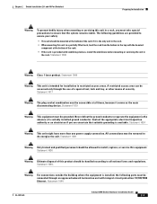
...Warning Do not stack the chassis on the system or connect or disconnect cables during periods of the rack. • If the rack is the only unit in the rack. • When mounting this unit in a central office environment. Statement 171 Warning Warning statement 353 applies only to the... 353 Warning Do not work on any other equipment. Statement 1001 Warning Read the installation instructions before mounting or servicing the unit in a partially filled rack, load the rack from the bottom to ensure that is connected to the terminals. Statement 1004 Warning To prevent bodily injury...
...Warning Do not stack the chassis on the system or connect or disconnect cables during periods of the rack. • If the rack is the only unit in the rack. • When mounting this unit in a central office environment. Statement 171 Warning Warning statement 353 applies only to the... 353 Warning Do not work on any other equipment. Statement 1001 Warning Read the installation instructions before mounting or servicing the unit in a partially filled rack, load the rack from the bottom to ensure that is connected to the terminals. Statement 1004 Warning To prevent bodily injury...

Hardware Installation Guide
Page 58
...these conditions - You need to insert an inline optical attenuator in the rack. • Do not wall-mount the switch with its front panel facing down to prevent airflow restriction and...cabling is safely away from being accidentally removed. To order a cable guard, contact your Cisco representative and use shorter lengths of single-mode fiber-optic cable, you should insert a 5-... • Catalyst 2960-8TC-L, 2960-8TC-S, and 2960PD-8TT-L switches cable guard part number: CBLGRD-C2960-8TC= • Catalyst 2960G-8TC-L switch cable guard part number: CBLGRD-C2960G-8TC= The cable guard is ...
...these conditions - You need to insert an inline optical attenuator in the rack. • Do not wall-mount the switch with its front panel facing down to prevent airflow restriction and...cabling is safely away from being accidentally removed. To order a cable guard, contact your Cisco representative and use shorter lengths of single-mode fiber-optic cable, you should insert a 5-... • Catalyst 2960-8TC-L, 2960-8TC-S, and 2960PD-8TT-L switches cable guard part number: CBLGRD-C2960-8TC= • Catalyst 2960G-8TC-L switch cable guard part number: CBLGRD-C2960G-8TC= The cable guard is ...

Hardware Installation Guide
Page 59
...-8TT-L switch through a 10/100/1000 uplink port, which can order a kit containing the 19-inch rack-mounting brackets and hardware from an upstream PoE switch. Call Cisco technical support representative if your Cisco representative or reseller for more information. After a successful POST, disconnect the power cord from...You can receive power from Cisco. To power on the switch, connect one end of the AC power cord to the AC power connector on the switch and verify that is specific to the other end of tests that runs automatically to rack-mount the switch. POST lasts ...
...-8TT-L switch through a 10/100/1000 uplink port, which can order a kit containing the 19-inch rack-mounting brackets and hardware from an upstream PoE switch. Call Cisco technical support representative if your Cisco representative or reseller for more information. After a successful POST, disconnect the power cord from...You can receive power from Cisco. To power on the switch, connect one end of the AC power cord to the AC power connector on the switch and verify that is specific to the other end of tests that runs automatically to rack-mount the switch. POST lasts ...

Hardware Installation Guide
Page 60
...on page 2-18, and the "Connecting to a Dual-Purpose Port" section on the bottom of a desk or shelf with Rack-Mount Brackets), page 3-16 Desk- Doing so helps prevent airflow restriction and overheating. Note We strongly recommend that you attach the rubber... on the desk or shelf. or Shelf-Mounting (with Mounting Screws), page 3-8 • Wall-Mounting (with Mounting Screws), page 3-11 • Magnet Mounting, page 3-14 • Rack-Mounting, page 3-15 • Wall-Mounting (with or without Mounting Screws) This section is mounted on the desk or shelf. For information applicable...
...on page 2-18, and the "Connecting to a Dual-Purpose Port" section on the bottom of a desk or shelf with Rack-Mount Brackets), page 3-16 Desk- Doing so helps prevent airflow restriction and overheating. Note We strongly recommend that you attach the rubber... on the desk or shelf. or Shelf-Mounting (with Mounting Screws), page 3-8 • Wall-Mounting (with Mounting Screws), page 3-11 • Magnet Mounting, page 3-14 • Rack-Mounting, page 3-15 • Wall-Mounting (with or without Mounting Screws) This section is mounted on the desk or shelf. For information applicable...

Hardware Installation Guide
Page 69
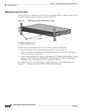
... an optional bracket kit that the system remains stable. Installing the Catalyst 2960 8-port switches in a partially filled rack, load the rack from Cisco. You can order a kit containing the 19-inch rack-mounting brackets and hardware from the bottom to the Catalyst 2960 8-port switches. The following guidelines are provided to ensure your safety...
... an optional bracket kit that the system remains stable. Installing the Catalyst 2960 8-port switches in a partially filled rack, load the rack from Cisco. You can order a kit containing the 19-inch rack-mounting brackets and hardware from the bottom to the Catalyst 2960 8-port switches. The following guidelines are provided to ensure your safety...
Hardware Installation Guide
Page 70
... Modules" section on page 2-18, and the "Connecting to a Dual-Purpose Port" section on the switch. You can order a kit containing the 19-inch rack-mounting brackets and hardware from Cisco. and 48-Port Switches)." 3-16 Catalyst 2960 Switch Hardware Installation Guide OL-7075-09 Installing the Switch Chapter 3 Switch Installation (8-Port Switches...
... Modules" section on page 2-18, and the "Connecting to a Dual-Purpose Port" section on the switch. You can order a kit containing the 19-inch rack-mounting brackets and hardware from Cisco. and 48-Port Switches)." 3-16 Catalyst 2960 Switch Hardware Installation Guide OL-7075-09 Installing the Switch Chapter 3 Switch Installation (8-Port Switches...

Hardware Installation Guide
Page 103
...B-1 to -DB-9 B-8 attaching the Cisco RPS warning 2-2, 2-6 auto-MDIX 1-11, 2-15, 2-20, B-1, B-3, C-2 autonegotiation 1-11 autonegotiation troubleshooting 4-4 OL-7075-09 INDEX B bodily injury prevention warning 2-2, 3-2 bodily injury warning 2-3, 2-6, 3-2, 3-15 brackets See mounting brackets C cable guard 1-19, 3-4..., B-1, B-3, C-2 pinouts B-6 See also connectors and cables circuit protection warning 2-3 Cisco IOS command-line interface 1-22 Catalyst 2960 Switch Hardware Installation Guide IN-1 and 24-inch racks 2-7, 3-15 A AC power connecting to 2-5, 3-5 connector 1-20 specifications A-2 to...
...B-1 to -DB-9 B-8 attaching the Cisco RPS warning 2-2, 2-6 auto-MDIX 1-11, 2-15, 2-20, B-1, B-3, C-2 autonegotiation 1-11 autonegotiation troubleshooting 4-4 OL-7075-09 INDEX B bodily injury prevention warning 2-2, 3-2 bodily injury warning 2-3, 2-6, 3-2, 3-15 brackets See mounting brackets C cable guard 1-19, 3-4..., B-1, B-3, C-2 pinouts B-6 See also connectors and cables circuit protection warning 2-3 Cisco IOS command-line interface 1-22 Catalyst 2960 Switch Hardware Installation Guide IN-1 and 24-inch racks 2-7, 3-15 A AC power connecting to 2-5, 3-5 connector 1-20 specifications A-2 to...

Hardware Installation Guide
Page 105
... 4-2 lightning activity warning 2-2, 3-2 link status troubleshooting 4-3 M Mode button 1-14 model descriptions 1-1 mounting, desk or shelf 2-14, 3-6 mounting, wall-mounting 2-11, 3-16 mounting brackets attaching 2-7 to 2-9 rack-mount 2-10, 3-16 N Network Assistant described 1-22 to configure switch 2-21, 3-18 network configuration examples...warning 2-3, 3-3 H HP OpenView 1-22 humidity, relative A-1 I installation assigning the IP address C-4 connecting to a power source C-4 mounting in a rack (8-port switches) 3-15 to 3-16 on desk or shelf 2-14, 3-6, 3-11 under a desk 3-8 using a magnet 3-14...
... 4-2 lightning activity warning 2-2, 3-2 link status troubleshooting 4-3 M Mode button 1-14 model descriptions 1-1 mounting, desk or shelf 2-14, 3-6 mounting, wall-mounting 2-11, 3-16 mounting brackets attaching 2-7 to 2-9 rack-mount 2-10, 3-16 N Network Assistant described 1-22 to configure switch 2-21, 3-18 network configuration examples...warning 2-3, 3-3 H HP OpenView 1-22 humidity, relative A-1 I installation assigning the IP address C-4 connecting to a power source C-4 mounting in a rack (8-port switches) 3-15 to 3-16 on desk or shelf 2-14, 3-6, 3-11 under a desk 3-8 using a magnet 3-14...
Hardware Installation Guide
Page 106
... 1-20 RPS connector 1-20 power supply warning 2-3, 3-3 procedures connection 2-14 to 2-20 installation 2-6 to 2-14, 3-5 to 3-18 product disposal warning 2-3, 3-3 R rack-mounting 2-7 to 2-10, 3-15 to 3-16 rack-mounting warning 2-3, 2-6, 3-2, 3-15 read the wall-mounting instructions warning 2-2, 3-11, 3-17 rear panel clearance 2-5, 3-4 description 1-19 to 1-21 redundant power supply See RPS removing SFP modules 2-17...
... 1-20 RPS connector 1-20 power supply warning 2-3, 3-3 procedures connection 2-14 to 2-20 installation 2-6 to 2-14, 3-5 to 3-18 product disposal warning 2-3, 3-3 R rack-mounting 2-7 to 2-10, 3-15 to 3-16 rack-mounting warning 2-3, 2-6, 3-2, 3-15 read the wall-mounting instructions warning 2-2, 3-11, 3-17 rear panel clearance 2-5, 3-4 description 1-19 to 1-21 redundant power supply See RPS removing SFP modules 2-17...

Hardware Installation Guide
Page 107
... Manager 1-22 switch descriptions 1-1 switch powering on 2-5, 3-5 system LED 1-15 T technical specifications A-1 telco racks 2-7, 3-15 Telnet, and accessing the CLI 1-22 temperature, operating A-1 terminal emulation software C-3 trained and ...settings 4-4 POST 4-1 spanning tree loops 4-4 speed, duplex, and autonegotiation 4-4 switch performance 4-4 troubleshooting spanning tree loops 4-4 W wall-mounting 2-11, 3-16 warnings attaching the Cisco RPS 2-2, 2-6 circuit protection 2-3 class 1 laser product 2-3, 3-2 disconnecting device 2-3 Ethernet cables 2-2, 3-2 Ethernet ports 3-3 ground connection...
... Manager 1-22 switch descriptions 1-1 switch powering on 2-5, 3-5 system LED 1-15 T technical specifications A-1 telco racks 2-7, 3-15 Telnet, and accessing the CLI 1-22 temperature, operating A-1 terminal emulation software C-3 trained and ...settings 4-4 POST 4-1 spanning tree loops 4-4 speed, duplex, and autonegotiation 4-4 switch performance 4-4 troubleshooting spanning tree loops 4-4 W wall-mounting 2-11, 3-16 warnings attaching the Cisco RPS 2-2, 2-6 circuit protection 2-3 class 1 laser product 2-3, 3-2 disconnecting device 2-3 Ethernet cables 2-2, 3-2 Ethernet ports 3-3 ground connection...
