Software Guide
Page 17
...T E R 78-15486-01 Configuring a Login Banner 27-4 Clearing the Login Banner 27-5 Enabling or Disabling the "Cisco Systems Console" Telnet Login Banner 27-5 Defining and Using Command Aliases 27-6 Defining and Using IP Aliases 27-7 Configuring ...Catalyst 4500 Series Switch 28-10 Understanding How Inline Power Works 28-11 Inline Power Management Modes 28-12 Power Requirements 28-12 Phone Detection Summary 28-14 Configuring Power Management 28-14 Setting Redundant Mode for the Catalyst 4500 Series Switches 28-14 Setting Combined Mode on the Catalyst 4500 Series Switches 28-15 Setting the DC...
...T E R 78-15486-01 Configuring a Login Banner 27-4 Clearing the Login Banner 27-5 Enabling or Disabling the "Cisco Systems Console" Telnet Login Banner 27-5 Defining and Using Command Aliases 27-6 Defining and Using IP Aliases 27-7 Configuring ...Catalyst 4500 Series Switch 28-10 Understanding How Inline Power Works 28-11 Inline Power Management Modes 28-12 Power Requirements 28-12 Phone Detection Summary 28-14 Configuring Power Management 28-14 Setting Redundant Mode for the Catalyst 4500 Series Switches 28-14 Setting Combined Mode on the Catalyst 4500 Series Switches 28-15 Setting the DC...

Software Guide
Page 411
... Sys-Status Uptime d,h:m:s Logout ok off ok 0,18:24:41 none PS1-Type PS2-Type PS3-Type WS-X4008-DC-650W WS-X4008 WS-X4008 Modem Baud Traffic Peak Peak-Time 78-15486-01 Catalyst 4500 Series, Catalyst 2948G, Catalyst 2980G Switches Software Configuration Guide-Release 8.1 27-3 Console> (enable) set system location Sunnyvale CA System location set system...
... Sys-Status Uptime d,h:m:s Logout ok off ok 0,18:24:41 none PS1-Type PS2-Type PS3-Type WS-X4008-DC-650W WS-X4008 WS-X4008 Modem Baud Traffic Peak Peak-Time 78-15486-01 Catalyst 4500 Series, Catalyst 2948G, Catalyst 2980G Switches Software Configuration Guide-Release 8.1 27-3 Console> (enable) set system location Sunnyvale CA System location set system...

Software Guide
Page 422
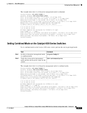
... in power supply bay (PS2). Note If you use the 1400 W DC power supply with different types or wattages in your switch has two power supplies. Combined mode requires that is provided by the power supplies in the Catalyst 4500 series switch are set to redundant mode. • Combined mode-Uses the power from...
... in power supply bay (PS2). Note If you use the 1400 W DC power supply with different types or wattages in your switch has two power supplies. Combined mode requires that is provided by the power supplies in the Catalyst 4500 series switch are set to redundant mode. • Combined mode-Uses the power from...

Software Guide
Page 423
... maximum available power for chassis and inline power for each power supply. 78-15486-01 Catalyst 4500 Series, Catalyst 2948G, Catalyst 2980G Switches Software Configuration Guide-Release 8.1 28-3 For more information about the 1400 W DC power supply, see the "1400 W DC Power Supply Guidelines and Restrictions" section on page 28-5. • When you use power supplies...
... maximum available power for chassis and inline power for each power supply. 78-15486-01 Catalyst 4500 Series, Catalyst 2948G, Catalyst 2980G Switches Software Configuration Guide-Release 8.1 28-3 For more information about the 1400 W DC power supply, see the "1400 W DC Power Supply Guidelines and Restrictions" section on page 28-5. • When you use power supplies...

Software Guide
Page 424
.... The backplane consumes 10 W in redundant mode. 4. The inline power has 0.96 efficiency. 5. For more information, see the "Power Management Limitations" section on page 28-4. The DC input can set combined mode, the switch displays this message: Insufficient power supplies present for specified configuration. 28-4 Catalyst 4500 Series, Catalyst 2948G, Catalyst 2980G Switches Software Configuration Guide-Release...
.... The backplane consumes 10 W in redundant mode. 4. The inline power has 0.96 efficiency. 5. For more information, see the "Power Management Limitations" section on page 28-4. The DC input can set combined mode, the switch displays this message: Insufficient power supplies present for specified configuration. 28-4 Catalyst 4500 Series, Catalyst 2948G, Catalyst 2980G Switches Software Configuration Guide-Release...

Software Guide
Page 425
...properly. 78-15486-01 Catalyst 4500 Series, Catalyst 2948G, Catalyst 2980G Switches Software Configuration Guide-Release 8.1 28-5 Chapter 28 Power Management Understanding How Power Management Works on the Catalyst 4500 Series Switches • Combined mode requires that you use the 1400 W DC power supply with Supervisor ...Engine II, use the 1400 W DC power supply with any other power supply, even for a...
...properly. 78-15486-01 Catalyst 4500 Series, Catalyst 2948G, Catalyst 2980G Switches Software Configuration Guide-Release 8.1 28-5 Chapter 28 Power Management Understanding How Power Management Works on the Catalyst 4500 Series Switches • Combined mode requires that you use the 1400 W DC power supply with Supervisor ...Engine II, use the 1400 W DC power supply with any other power supply, even for a...

Software Guide
Page 426
... mode) or to one primary plus one redundant power supply). The Catalyst 4000 series switch chassis supports only the 400 W AC, 400 W DC, and 650 W DC power supplies and allows you use the 1+1 redundancy mode in these hardware configurations: • One Catalyst 4006 chassis with a WS-X4013 supervisor engine with two 400 W power supplies (in 1+1 redundancy...
... mode) or to one primary plus one redundant power supply). The Catalyst 4000 series switch chassis supports only the 400 W AC, 400 W DC, and 650 W DC power supplies and allows you use the 1+1 redundancy mode in these hardware configurations: • One Catalyst 4006 chassis with a WS-X4013 supervisor engine with two 400 W power supplies (in 1+1 redundancy...

Software Guide
Page 431
... system power (see Table 28-2 on the circuit, the switch does not supply it. Table 28-3 Switch Components Supporting Inline Power Switch Chassis Catalyst 4006 Catalyst 4503 Catalyst 4506 Modules WS-X4148-RJ45V WS-X4148-RJ45V Power Supplies Catalyst 4000 Series Power Entry Module (PEM) 1300 W AC 2800 W AC 1400 W DC You can also be connected to an AC power...
... system power (see Table 28-2 on the circuit, the switch does not supply it. Table 28-3 Switch Components Supporting Inline Power Switch Chassis Catalyst 4006 Catalyst 4503 Catalyst 4506 Modules WS-X4148-RJ45V WS-X4148-RJ45V Power Supplies Catalyst 4000 Series Power Entry Module (PEM) 1300 W AC 2800 W AC 1400 W DC You can also be connected to an AC power...
Software Guide
Page 435
... mode on the Catalyst 4500 series switch, perform this task in privileged mode: Step 1 Step 2 Task Command Set the system power management mode set power budget 1 Console> (enable) show environment power mode and the current power usage for 2500Watts DC input Power Budget is...@12V) Remaining Power (excluding voice power): 1150 Watts (95.83 Amps @12V) Console>(enable) 78-15486-01 Catalyst 4500 Series, Catalyst 2948G, Catalyst 2980G Switches Software Configuration Guide-Release 8.1 28-15 Verify the system power management show environment power Total Inline Power Available: 774....
... mode on the Catalyst 4500 series switch, perform this task in privileged mode: Step 1 Step 2 Task Command Set the system power management mode set power budget 1 Console> (enable) show environment power mode and the current power usage for 2500Watts DC input Power Budget is...@12V) Remaining Power (excluding voice power): 1150 Watts (95.83 Amps @12V) Console>(enable) 78-15486-01 Catalyst 4500 Series, Catalyst 2948G, Catalyst 2980G Switches Software Configuration Guide-Release 8.1 28-15 Verify the system power management show environment power Total Inline Power Available: 774....

Software Guide
Page 436
... the setting: Console> (enable) set power dcinput 5000 Console> (enable) show environment power 28-16 Catalyst 4500 Series, Catalyst 2948G, Catalyst 2980G Switches Software Configuration Guide-Release 8.1 78-15486-01 Command set the DC power input for the 1400 W DC power supply, perform this task in privileged mode: Step 1 Step 2 Task Set the input wattage for...
... the setting: Console> (enable) set power dcinput 5000 Console> (enable) show environment power 28-16 Catalyst 4500 Series, Catalyst 2948G, Catalyst 2980G Switches Software Configuration Guide-Release 8.1 78-15486-01 Command set the DC power input for the 1400 W DC power supply, perform this task in privileged mode: Step 1 Step 2 Task Set the input wattage for...

Software Guide
Page 441
... any 10/100 or 10/100/1000 switching module. The Catalyst 4006 switch can only provide a maximum 400 W of IP Phones, page 29-2 • Configuring VoIP on a Switch, page 29-3 Hardware and Software Requirements The hardware and software requirements for the Catalyst 4500 series switches and Cisco CallManager are as follows: • Catalyst 4006, Catalyst 4500 series, Catalyst 5000 family, and Catalyst 6500 series switches running...
... any 10/100 or 10/100/1000 switching module. The Catalyst 4006 switch can only provide a maximum 400 W of IP Phones, page 29-2 • Configuring VoIP on a Switch, page 29-3 Hardware and Software Requirements The hardware and software requirements for the Catalyst 4500 series switches and Cisco CallManager are as follows: • Catalyst 4006, Catalyst 4500 series, Catalyst 5000 family, and Catalyst 6500 series switches running...

Software Guide
Page 593
...30-10 audience xxiii authentication See 802.1x authentication, Kerberos authentication; INDEX Numerics 10/100 port speed, setting 4-4 1400W DC power supply 28-5 802.1Q example 11-9, 11-19 mapping VLANs to ISL 10-11 overview 11-1 restrictions 11-4 supported switches ...autonegotiation duplex 4-5 speed 4-5 trunks 11-2 auxiliary VLANs configuring 10-13 dynamic VLAN membership 12-14 software support 10-5 B BackboneFast adding a switch (figure) 8-7 78-15486-01 Catalyst 4500 Series, Catalyst 2948G, Catalyst 2980G Switches Software Configuration Guide-Release 8.1 IN-1 NTP authentication; TACACS+...
...30-10 audience xxiii authentication See 802.1x authentication, Kerberos authentication; INDEX Numerics 10/100 port speed, setting 4-4 1400W DC power supply 28-5 802.1Q example 11-9, 11-19 mapping VLANs to ISL 10-11 overview 11-1 restrictions 11-4 supported switches ...autonegotiation duplex 4-5 speed 4-5 trunks 11-2 auxiliary VLANs configuring 10-13 dynamic VLAN membership 12-14 software support 10-5 B BackboneFast adding a switch (figure) 8-7 78-15486-01 Catalyst 4500 Series, Catalyst 2948G, Catalyst 2980G Switches Software Configuration Guide-Release 8.1 IN-1 NTP authentication; TACACS+...