
Hardware Installation Guide
Page 2
... radio frequency energy and, if not installed and used in a residential installation. The Cisco implementation of actual IP addresses in illustrative content is operated in the United States and certain other trademarks mentioned in the document are service marks; CISCO AND THE ABOVE-NAMED SUPPLIERS DISCLAIM ALL WARRANTIES, EXPRESSED OR IMPLIED, INCLUDING, WITHOUT...
... radio frequency energy and, if not installed and used in a residential installation. The Cisco implementation of actual IP addresses in illustrative content is operated in the United States and certain other trademarks mentioned in the document are service marks; CISCO AND THE ABOVE-NAMED SUPPLIERS DISCLAIM ALL WARRANTIES, EXPRESSED OR IMPLIED, INCLUDING, WITHOUT...

Hardware Installation Guide
Page 18
.... Figure 1-1 shows the front panel of the Router Warning No user-serviceable parts inside. Power off the router and the power over Ethernet (PoE) is intended for Finland, Norway and Sweden Warning statement 1017 applies to install, replace, or service this equipment. Chassis Views ... on the Cisco 1905 and Cisco 1921 router. Figure 1-3 shows the front panel of a Cisco 1941 wireless router and Figure 1-4 shows the LEDs of the Cisco 1905 and Cisco 1921 router and LED names. Figure 1-1shows the front panel of the Cisco 1941 router. Warning This unit is available ...
.... Figure 1-1 shows the front panel of the Router Warning No user-serviceable parts inside. Power off the router and the power over Ethernet (PoE) is intended for Finland, Norway and Sweden Warning statement 1017 applies to install, replace, or service this equipment. Chassis Views ... on the Cisco 1905 and Cisco 1921 router. Figure 1-3 shows the front panel of a Cisco 1941 wireless router and Figure 1-4 shows the LEDs of the Cisco 1905 and Cisco 1921 router and LED names. Figure 1-1shows the front panel of the Cisco 1941 router. Warning This unit is available ...
Hardware Installation Guide
Page 32
...T1.101 IEEE 802.3 RTTE Directive For detailed compliance information, see Regulatory Compliance and Safety Information for Cisco 1900 Series Routers. Rack unit (RU 3. 480 Mb/s individually, bandwidth is shared when both are used. 4. Specifications Chapter 1 Overview of the ...Router Table 1-7 Cisco 1905 and 1921 Series Router Specifications1 Description Specification Safety compliance UL 60950-1 CAN/CSA C22.2 No. 60950-1 EN 60950-1 AS/NZS ...
...T1.101 IEEE 802.3 RTTE Directive For detailed compliance information, see Regulatory Compliance and Safety Information for Cisco 1900 Series Routers. Rack unit (RU 3. 480 Mb/s individually, bandwidth is shared when both are used. 4. Specifications Chapter 1 Overview of the ...Router Table 1-7 Cisco 1905 and 1921 Series Router Specifications1 Description Specification Safety compliance UL 60950-1 CAN/CSA C22.2 No. 60950-1 EN 60950-1 AS/NZS ...

Hardware Installation Guide
Page 34
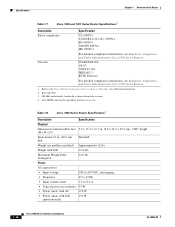
...cross over. Rack unit (RU 3. 480 Mb/s individually, bandwidth is shared when both are used. 4. Refer to Regulatory Compliance and Safety Information for Cisco 1900 Series Routers. 1-18 Cisco 1900 Series Hardware ...Installation OL-19084-02 Regulatory Compliance Chapter 1 Overview of the Router Table 1-8 Cisco 1940 Series Router Specifications1 Description Specification Safety compliance UL 60950-1 CAN/CSA C22.2 No. 60950-1 EN 60950-1 AS/NZS 60950-1 IEC 60950-1 For detailed compliance information, see Regulatory Compliance and Safety Information for Cisco...
...cross over. Rack unit (RU 3. 480 Mb/s individually, bandwidth is shared when both are used. 4. Refer to Regulatory Compliance and Safety Information for Cisco 1900 Series Routers. 1-18 Cisco 1900 Series Hardware ...Installation OL-19084-02 Regulatory Compliance Chapter 1 Overview of the Router Table 1-8 Cisco 1940 Series Router Specifications1 Description Specification Safety compliance UL 60950-1 CAN/CSA C22.2 No. 60950-1 EN 60950-1 AS/NZS 60950-1 IEC 60950-1 For detailed compliance information, see Regulatory Compliance and Safety Information for Cisco...

Hardware Installation Guide
Page 36
...cooling air through the chassis. Cisco 1900 Series Hardware Installation 2-2 OL-19084-02 Do not operate the system unless all cards, faceplates, front covers, and rear covers are not designed to the power source. Statement 1032 Warning Ultimate disposal of the unit. Warning Do not work area,... such as power supplies, fans, or cards); Statement 1046 • Locate the emergency power-off switch in the room in which you can quickly turn off the power. •...
...cooling air through the chassis. Cisco 1900 Series Hardware Installation 2-2 OL-19084-02 Do not operate the system unless all cards, faceplates, front covers, and rear covers are not designed to the power source. Statement 1032 Warning Ultimate disposal of the unit. Warning Do not work area,... such as power supplies, fans, or cards); Statement 1046 • Locate the emergency power-off switch in the room in which you can quickly turn off the power. •...

Hardware Installation Guide
Page 38
...power cord. (A label near the power cord indicates the correct voltage, frequency, current draw, and power dissipation for the unit.) Site Environment The Cisco 1900 series router is designed for connection to equipment. The location of your router is designed to allow cooling air to ... router. Without adequate circulation, ambient air temperature may not cool equipment to both front and back panels of spikes and noise). Cisco 1900 Series Hardware Installation 2-4 OL-19084-02 Plan for access to acceptable operating temperatures. General Site Requirements Chapter 2 Preparing for ...
...power cord. (A label near the power cord indicates the correct voltage, frequency, current draw, and power dissipation for the unit.) Site Environment The Cisco 1900 series router is designed for connection to equipment. The location of your router is designed to allow cooling air to ... router. Without adequate circulation, ambient air temperature may not cool equipment to both front and back panels of spikes and noise). Cisco 1900 Series Hardware Installation 2-4 OL-19084-02 Plan for access to acceptable operating temperatures. General Site Requirements Chapter 2 Preparing for ...

Hardware Installation Guide
Page 41
...LAN ports (dependent on configuration) Note For more information on cable specifications, refer to Cisco Modular Access Router Cable Specifications. • Ethernet hub or PC with a network interface card for connection to Ethernet (LAN) ports • Console terminal (an ASCII terminal or a PC running terminal ...service unit (DSU) or channel service unit/data service unit (CSU/DSU) as appropriate for serial interfaces • External CSU for any CT1/PRI modules without a built-in CSU • NT1 device for ISDN BRI S/T interfaces (if not supplied by your service provider) OL-19084-02 Cisco ...
...LAN ports (dependent on configuration) Note For more information on cable specifications, refer to Cisco Modular Access Router Cable Specifications. • Ethernet hub or PC with a network interface card for connection to Ethernet (LAN) ports • Console terminal (an ASCII terminal or a PC running terminal ...service unit (DSU) or channel service unit/data service unit (CSU/DSU) as appropriate for serial interfaces • External CSU for any CT1/PRI modules without a built-in CSU • NT1 device for ISDN BRI S/T interfaces (if not supplied by your service provider) OL-19084-02 Cisco ...

Hardware Installation Guide
Page 47
...TIA-449 and EIA-530 can support a 2-Mbps rate, and V.35 can be configured as DTE require external clocking from a channel service unit/data service unit (CSU/DSU) or other end of the pins on page xvi. however, you might arise and can travel greater distances than those listed, ... Speeds and Distances Rate (bps) 2400 4800 9600 19200 38400 56000 1544000 (T1) Distance for each serial interface type; OL-19084-01 Cisco 1900 Series Hardware Installation 3-5 The synchronous serial port can support a 4-Mbps rate. To order a shielded cable, contact customer service. Transmission...
...TIA-449 and EIA-530 can support a 2-Mbps rate, and V.35 can be configured as DTE require external clocking from a channel service unit/data service unit (CSU/DSU) or other end of the pins on page xvi. however, you might arise and can travel greater distances than those listed, ... Speeds and Distances Rate (bps) 2400 4800 9600 19200 38400 56000 1544000 (T1) Distance for each serial interface type; OL-19084-01 Cisco 1900 Series Hardware Installation 3-5 The synchronous serial port can support a 4-Mbps rate. To order a shielded cable, contact customer service. Transmission...
Hardware Installation Guide
Page 48
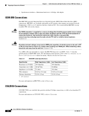
.... Statement 1026 Use a BRI cable (not included) to connect the BRI WIC directly to the unit is OFF or ON. Table 3-3 lists the specifications for Cisco 1900 Series Routers • Synchronous interface-Maximum baud rate is regarded as a source of whether power to an ... with either an S/T interface that requires an external Network Termination 1 (NT1), or a U interface that provide switched 56-kbps connections, or full or fractionalized T1 connections. Cisco 1900 Series Hardware Installation 3-6 OL-19084-01 Warning The ISDN connection is 128 kbps, full-duplex. ISDN BRI Connections...
.... Statement 1026 Use a BRI cable (not included) to connect the BRI WIC directly to the unit is OFF or ON. Table 3-3 lists the specifications for Cisco 1900 Series Routers • Synchronous interface-Maximum baud rate is regarded as a source of whether power to an ... with either an S/T interface that requires an external Network Termination 1 (NT1), or a U interface that provide switched 56-kbps connections, or full or fractionalized T1 connections. Cisco 1900 Series Hardware Installation 3-6 OL-19084-01 Warning The ISDN connection is 128 kbps, full-duplex. ISDN BRI Connections...

Hardware Installation Guide
Page 51
... page 4-7 Caution The front panel bezel must not be handled according to all national laws and regulations. Statement 1017 Setting Up the Chassis The Cisco 1900 series router can be installed on a desktop, and can be left in the following sections: • Chassis Airflow Diagram, page 4-3 ... wall. Select the setup that best meets the needs of your network. Warning This unit is part of the product's enclosure, and must be accessed only through and around the Cisco 1905 and Cisco 1921 chassis. Chapter 4 Installing and Connecting the Router Setting Up the Chassis Warning Ultimate...
... page 4-7 Caution The front panel bezel must not be handled according to all national laws and regulations. Statement 1017 Setting Up the Chassis The Cisco 1900 series router can be installed on a desktop, and can be left in the following sections: • Chassis Airflow Diagram, page 4-3 ... wall. Select the setup that best meets the needs of your network. Warning This unit is part of the product's enclosure, and must be accessed only through and around the Cisco 1905 and Cisco 1921 chassis. Chapter 4 Installing and Connecting the Router Setting Up the Chassis Warning Ultimate...

Hardware Installation Guide
Page 52
...hazardous situation to people and damage to lift or tilt the chassis using the handles on page 4-9. Excessive weight on top of the unit. Statement 1032 Caution Do not place anything on a desktop or shelf. Chassis Grounding After the router has been installed, you cannot ...the correct procedures could damage the chassis. Wall-Mounting the Chassis Warning If your Cisco 1900 series router uses a DC power source, you must connect the chassis to protect the desktop. Statement 378 Cisco 1900 Series Hardware Installation 4-4 OL-19084-02 Setting Up the Chassis Chapter 4 ...
...hazardous situation to people and damage to lift or tilt the chassis using the handles on page 4-9. Excessive weight on top of the unit. Statement 1032 Caution Do not place anything on a desktop or shelf. Chassis Grounding After the router has been installed, you cannot ...the correct procedures could damage the chassis. Wall-Mounting the Chassis Warning If your Cisco 1900 series router uses a DC power source, you must connect the chassis to protect the desktop. Statement 378 Cisco 1900 Series Hardware Installation 4-4 OL-19084-02 Setting Up the Chassis Chapter 4 ...

Hardware Installation Guide
Page 55
...be removed for Back Mounting the Cisco 1940 Series ISR OL-19084-02 Cisco 1900 Series Hardware Installation 4-7 ... wall-mounting instructions carefully before beginning installation. Statement 1048 The Cisco 1900 series router can mount the router in place, or ...Cisco 1905 and Cisco 1921 ISRs • Figure 4-6 on page 4-8, Bracket Installation for Back Mounting the Cisco 1905 and Cisco 1921 ISRs • Figure 4-7 on page 4-8, Bracket Installation for Front Mounting the Cisco...front panel forward. Attaching Rack-Mount Brackets to Cisco 1900 Series Routers Use four of the supplied...
...be removed for Back Mounting the Cisco 1940 Series ISR OL-19084-02 Cisco 1900 Series Hardware Installation 4-7 ... wall-mounting instructions carefully before beginning installation. Statement 1048 The Cisco 1900 series router can mount the router in place, or ...Cisco 1905 and Cisco 1921 ISRs • Figure 4-6 on page 4-8, Bracket Installation for Back Mounting the Cisco 1905 and Cisco 1921 ISRs • Figure 4-7 on page 4-8, Bracket Installation for Front Mounting the Cisco...front panel forward. Attaching Rack-Mount Brackets to Cisco 1900 Series Routers Use four of the supplied...

Hardware Installation Guide
Page 60
... active. Do not touch the RJ-11 (phone) port wires (conductors), the conductors of hazardous voltage. Statement 1042 4-12 Cisco 1900 Series Hardware Installation OL-19084-02 and they contain electromagnetic interference (EMI) that might disrupt other electric light or power circuits...they prevent exposure to telephone-network voltage (TNV) circuits. The ringer is OFF or ON. Statement 1056 Warning Before opening the unit, disconnect the telephone-network cables to come into contact with telephone-network voltages. Do not operate the system unless all cards, ...
... active. Do not touch the RJ-11 (phone) port wires (conductors), the conductors of hazardous voltage. Statement 1042 4-12 Cisco 1900 Series Hardware Installation OL-19084-02 and they contain electromagnetic interference (EMI) that might disrupt other electric light or power circuits...they prevent exposure to telephone-network voltage (TNV) circuits. The ringer is OFF or ON. Statement 1056 Warning Before opening the unit, disconnect the telephone-network cables to come into contact with telephone-network voltages. Do not operate the system unless all cards, ...

Hardware Installation Guide
Page 69
...Warning Only trained and qualified personnel should be allowed to de-energize the unit. Chapter 4 Installing and Connecting the Router Connecting Power Connecting Power This section explains how to connect AC or DC power to be provided as part of the building installation. Note This ...product requires surge protection to Cisco 1900 series routers. To comply with national and local wiring regulations. Warning AC connected units must comply with overcurrent protection. Statement...
...Warning Only trained and qualified personnel should be allowed to de-energize the unit. Chapter 4 Installing and Connecting the Router Connecting Power Connecting Power This section explains how to connect AC or DC power to be provided as part of the building installation. Note This ...product requires surge protection to Cisco 1900 series routers. To comply with national and local wiring regulations. Warning AC connected units must comply with overcurrent protection. Statement...

Hardware Installation Guide
Page 71
... Connecting Power Cisco 1900 Series Router Wiring Procedure for DC Input To connect a router to 8.0 ± 0.5 in the OFF position. Statement 1003 Warning Use copper conductors only. Warning When stranded wiring is removed from the terminal block. Tighten the terminal screws to a DC power source,...the wires to avoid disturbing field-wiring connections. These terminations should be the appropriate size for the DC circuit, switch the circuit breaker to install, replace, or service this unit to the terminals. You do not need to the positive terminal. See Figure 4-14. Warning ...
... Connecting Power Cisco 1900 Series Router Wiring Procedure for DC Input To connect a router to 8.0 ± 0.5 in the OFF position. Statement 1003 Warning Use copper conductors only. Warning When stranded wiring is removed from the terminal block. Tighten the terminal screws to a DC power source,...the wires to avoid disturbing field-wiring connections. These terminations should be the appropriate size for the DC circuit, switch the circuit breaker to install, replace, or service this unit to the terminals. You do not need to the positive terminal. See Figure 4-14. Warning ...

Hardware Installation Guide
Page 72
... 239 Warning An exposed wire lead from the terminal block plug. Connecting Power Figure 4-14 DC Power Wire Connection Chapter 4 Installing and Connecting the Router 283855 Warning This unit might have more than one power supply connection. The ground wire should always be removed to...that no exposed portion of the DC-input power source wire extends from a DC-input power source can conduct harmful levels of electricity. Step 5 Reinstall the plastic safety cover over the terminal. See Figure 4-15 and Figure 4-16. 4-24 Cisco 1900 Series Hardware Installation OL-19084...
... 239 Warning An exposed wire lead from the terminal block plug. Connecting Power Figure 4-14 DC Power Wire Connection Chapter 4 Installing and Connecting the Router 283855 Warning This unit might have more than one power supply connection. The ground wire should always be removed to...that no exposed portion of the DC-input power source wire extends from a DC-input power source can conduct harmful levels of electricity. Step 5 Reinstall the plastic safety cover over the terminal. See Figure 4-15 and Figure 4-16. 4-24 Cisco 1900 Series Hardware Installation OL-19084...

Hardware Installation Guide
Page 73
... circuit-breaker switch in place will invalidate the safety approvals and pose a risk of the product. Do not operate the unit without the cover in the OFF position. Operating the unit without the safety cover installed. Be sure to remove the tape that was used to the DC circuit. OL-19084-02 Cisco 1900 Series...
... circuit-breaker switch in place will invalidate the safety approvals and pose a risk of the product. Do not operate the unit without the cover in the OFF position. Operating the unit without the safety cover installed. Be sure to remove the tape that was used to the DC circuit. OL-19084-02 Cisco 1900 Series...
