Installation Guide
Page 18
... to bottom) Figure 1-2 Catalyst 6503 Switch-Rear View 63031 Power supply 2 (redundant) Power supply 1 INPUT FAN OUTPUT OK OK FAIL INPUT FAN OUTPUT OK OK FAIL Catalyst 6500 Series Ethernet Modules Installation Guide 1-2 OL-6265-03 Table 1-2 lists specifications of the Catalyst 6503 switch chassis. Catalyst 6503 Switch Chapter 1 Catalyst 6500 Series Switch Chassis Overview Catalyst 6503 Switch The Catalyst 6503 switch is a 3-slot horizontal...
... to bottom) Figure 1-2 Catalyst 6503 Switch-Rear View 63031 Power supply 2 (redundant) Power supply 1 INPUT FAN OUTPUT OK OK FAIL INPUT FAN OUTPUT OK OK FAIL Catalyst 6500 Series Ethernet Modules Installation Guide 1-2 OL-6265-03 Table 1-2 lists specifications of the Catalyst 6503 switch chassis. Catalyst 6503 Switch Chapter 1 Catalyst 6500 Series Switch Chassis Overview Catalyst 6503 Switch The Catalyst 6503 switch is a 3-slot horizontal...

Installation Guide
Page 19
... AC-input and one or two power supplies. OL-6265-03 Catalyst 6500 Series Ethernet Modules Installation Guide 1-3 Chapter 1 Catalyst 6500 Series Switch Chassis Overview Catalyst 6503 Switch Table 1-1 Catalyst 6503 Switch Features Feature Chassis Power supplies Description Three horizontal slots. Slots are supported: - 950 W AC-input power supply (PWR-950-AC) - 950 W DC-input power supply (PWR-950-DC) - 1400...
... AC-input and one or two power supplies. OL-6265-03 Catalyst 6500 Series Ethernet Modules Installation Guide 1-3 Chapter 1 Catalyst 6500 Series Switch Chassis Overview Catalyst 6503 Switch Table 1-1 Catalyst 6503 Switch Features Feature Chassis Power supplies Description Three horizontal slots. Slots are supported: - 950 W AC-input power supply (PWR-950-AC) - 950 W DC-input power supply (PWR-950-DC) - 1400...
Installation Guide
Page 22
..., 2 AC-input PEMs, and 2 AC-input power supplies: 85.4 lb (38.7 kg). • FAN-MOD-3 (standard fan tray)-170 CFM • FAN-MOD-3HS (optional high-speed fan tray)-270 CFM Note To maintain proper air circulation through the Catalyst switch chassis, we recommend that are triggered at 104°...to 6500 feet (0 to 2000 m) Designed and tested for operation: 32° to 130°F (0° to 55°C) Note The Catalyst 6500 series switches are equipped with internal air temperature sensors that you maintain a minimum 6-inch (15 cm) separation between the hot air exhaust on one chassis and...
..., 2 AC-input PEMs, and 2 AC-input power supplies: 85.4 lb (38.7 kg). • FAN-MOD-3 (standard fan tray)-170 CFM • FAN-MOD-3HS (optional high-speed fan tray)-270 CFM Note To maintain proper air circulation through the Catalyst switch chassis, we recommend that are triggered at 104°...to 6500 feet (0 to 2000 m) Designed and tested for operation: 32° to 130°F (0° to 55°C) Note The Catalyst 6500 series switches are equipped with internal air temperature sensors that you maintain a minimum 6-inch (15 cm) separation between the hot air exhaust on one chassis and...
Installation Guide
Page 23
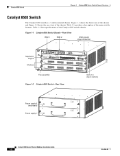
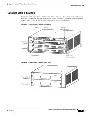
... shows the rear view of the major switch features. Table 1-4 lists the specifications of the Catalyst 6503-E switch chassis. Chapter 1 Catalyst 6500 Series Switch Chassis Overview Catalyst 6503-E Switch Catalyst 6503-E Switch The Catalyst 6503-E switch is a 3-slot horizontal chassis. Figure 1-3 Catalyst 6503-E Switch-Front View PEM 1 PEM 2 ESD ... 15 16 LINK LINK LINK LINK Fan assembly Slots 1-3 (top to bottom) Figure 1-4 Catalyst 6503-E Switch-Rear View 63031 Power supply 2 (redundant) Power supply 1 INPUT OK FAN OUTPUT OK FAIL INPUT FAN OUTPUT OK OK FAIL OL-6265-03...
... shows the rear view of the major switch features. Table 1-4 lists the specifications of the Catalyst 6503-E switch chassis. Chapter 1 Catalyst 6500 Series Switch Chassis Overview Catalyst 6503-E Switch Catalyst 6503-E Switch The Catalyst 6503-E switch is a 3-slot horizontal chassis. Figure 1-3 Catalyst 6503-E Switch-Front View PEM 1 PEM 2 ESD ... 15 16 LINK LINK LINK LINK Fan assembly Slots 1-3 (top to bottom) Figure 1-4 Catalyst 6503-E Switch-Rear View 63031 Power supply 2 (redundant) Power supply 1 INPUT OK FAN OUTPUT OK FAIL INPUT FAN OUTPUT OK OK FAIL OL-6265-03...

Installation Guide
Page 24
... information and specifications for each supervisor engine must have its own, which means all AC power supply inputs are isolated. • Single power supplies are installed in the same chassis. - Power supplies can be configured in the Catalyst 6500 Series Switches Installation Guide. Each supervisor engine must have the resources to run the configured features...
... information and specifications for each supervisor engine must have its own, which means all AC power supply inputs are isolated. • Single power supplies are installed in the same chassis. - Power supplies can be configured in the Catalyst 6500 Series Switches Installation Guide. Each supervisor engine must have the resources to run the configured features...
Installation Guide
Page 26
...; Chassis can cause the chassis to overheat and the system to fail. WS-C6503-E-FAN-282 CFM Note To maintain proper air circulation through the Catalyst switch chassis, we recommend that you maintain a minimum 15 cm (6-inch) separation between the hot air exhaust on one chassis and the air intake on another... ETS 300-119 standards. • Chassis only: 33 lb (15 kg). • Chassis fully configured with 1 supervisor engine, 2 modules, 2 AC-input PEMs, and 2 AC-input power supplies: 85.4 lb (38.7 kg).
...; Chassis can cause the chassis to overheat and the system to fail. WS-C6503-E-FAN-282 CFM Note To maintain proper air circulation through the Catalyst switch chassis, we recommend that you maintain a minimum 15 cm (6-inch) separation between the hot air exhaust on one chassis and the air intake on another... ETS 300-119 standards. • Chassis only: 33 lb (15 kg). • Chassis fully configured with 1 supervisor engine, 2 modules, 2 AC-input PEMs, and 2 AC-input power supplies: 85.4 lb (38.7 kg).
Installation Guide
Page 27
.... Table 1-6 lists the specifications of the chassis. Table 1-5 provides a description of major switch features. Figure 1-5 Catalyst 6504-E Switch-Front View 126559 Supervisor Engine Redundant Supervisor Engine OSMs FAN STATUS STATUS STATUS Slots 1-4 (top to bottom) Figure 1-6 Catalyst 6504-E Switch-Rear View Power Supply 2 (redundant) Power Supply 1 100-240V-16A 50/60Hz 100-240V-16A 50/60Hz PWR...
.... Table 1-6 lists the specifications of the chassis. Table 1-5 provides a description of major switch features. Figure 1-5 Catalyst 6504-E Switch-Front View 126559 Supervisor Engine Redundant Supervisor Engine OSMs FAN STATUS STATUS STATUS Slots 1-4 (top to bottom) Figure 1-6 Catalyst 6504-E Switch-Rear View Power Supply 2 (redundant) Power Supply 1 100-240V-16A 50/60Hz 100-240V-16A 50/60Hz PWR...

Installation Guide
Page 28
... redundant or nonredundant mode. • All Catalyst 6500 series AC-input power supplies require single-phase source AC. Catalyst 6504-E Switch Chapter 1 Catalyst 6500 Series Switch Chassis Overview Table 1-5 Catalyst 6504-E Switch Features Feature Chassis Power supplies Description Four horizontal slots. Slots are... Supervisor Engine 720, and Supervisor Engine 720-10GE. - The following power supplies are installed in the Catalyst 6500 Series Switches Installation Guide. PWR-2700-AC/4 (2700 W AC-input power supply) - Switch Fabric Modules (WS-C6500-SFM and WS-X6500-SFM2) are numbered ...
... redundant or nonredundant mode. • All Catalyst 6500 series AC-input power supplies require single-phase source AC. Catalyst 6504-E Switch Chapter 1 Catalyst 6500 Series Switch Chassis Overview Table 1-5 Catalyst 6504-E Switch Features Feature Chassis Power supplies Description Four horizontal slots. Slots are... Supervisor Engine 720, and Supervisor Engine 720-10GE. - The following power supplies are installed in the Catalyst 6500 Series Switches Installation Guide. PWR-2700-AC/4 (2700 W AC-input power supply) - Switch Fabric Modules (WS-C6500-SFM and WS-X6500-SFM2) are numbered ...

Installation Guide
Page 30
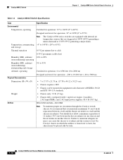
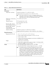
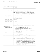
... Note To maintain proper air circulation through the Catalyst switch chassis, we recommend that are equipped with 2 supervisor engines, 2 modules, and 2 AC-input power supplies: 97 lb (43.99 kg). On Catalyst chassis in equipment racks that meet ANSI/EIA ... air space can be placed side-by-side. 1-14 Catalyst 6500 Series Ethernet Modules Installation Guide OL-6265-03 Catalyst 6504-E Switch Chapter 1 Catalyst 6500 Series Switch Chassis Overview Table 1-6 Catalyst 6504-E Switch Specifications Item Environmental Temperature, operating Temperature, nonoperating and storage Thermal...
... Note To maintain proper air circulation through the Catalyst switch chassis, we recommend that are equipped with 2 supervisor engines, 2 modules, and 2 AC-input power supplies: 97 lb (43.99 kg). On Catalyst chassis in equipment racks that meet ANSI/EIA ... air space can be placed side-by-side. 1-14 Catalyst 6500 Series Ethernet Modules Installation Guide OL-6265-03 Catalyst 6504-E Switch Chapter 1 Catalyst 6500 Series Switch Chassis Overview Table 1-6 Catalyst 6504-E Switch Specifications Item Environmental Temperature, operating Temperature, nonoperating and storage Thermal...
Installation Guide
Page 31
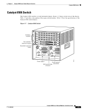
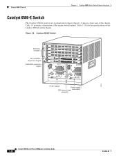
Figure 1-7 shows a front view of the major switch features. Figure 1-7 Catalyst 6506 Switch LINK LINK LINK Switching modules Fan assembly Supervisor engine Redundant supervisor engine 1 ...Power supply 1 Power supply 2 ESD ground strap (redundant) connector 18224 OL-6265-03 Catalyst 6500 Series Ethernet Modules Installation Guide 1-15 Table 1-7 provides a description of the chassis. Table 1-8 lists the specifications of the Catalyst 6506 switch chassis. Chapter 1 Catalyst 6500 Series Switch Chassis Overview Catalyst 6506 Switch Catalyst 6506 Switch The Catalyst 6506 switch...
Figure 1-7 shows a front view of the major switch features. Figure 1-7 Catalyst 6506 Switch LINK LINK LINK Switching modules Fan assembly Supervisor engine Redundant supervisor engine 1 ...Power supply 1 Power supply 2 ESD ground strap (redundant) connector 18224 OL-6265-03 Catalyst 6500 Series Ethernet Modules Installation Guide 1-15 Table 1-7 provides a description of the chassis. Table 1-8 lists the specifications of the Catalyst 6506 switch chassis. Chapter 1 Catalyst 6500 Series Switch Chassis Overview Catalyst 6506 Switch Catalyst 6506 Switch The Catalyst 6506 switch...

Installation Guide
Page 32
... AC. WS-CAC-4000W-US (4000 W AC-input power supply) - Installed power supplies can be configured in the Catalyst 6500 Series Switches Installation Guide. • Installed power supplies can be out of different wattage ratings. Catalyst 6506 Switch Chapter 1 Catalyst 6500 Series Switch Chassis Overview Table 1-7 Catalyst 6506 Switch Features Feature Chassis Power supplies Descriptions Six horizontal slots. Slots are installed in...
... AC. WS-CAC-4000W-US (4000 W AC-input power supply) - Installed power supplies can be configured in the Catalyst 6500 Series Switches Installation Guide. • Installed power supplies can be out of different wattage ratings. Catalyst 6506 Switch Chapter 1 Catalyst 6500 Series Switch Chassis Overview Table 1-7 Catalyst 6506 Switch Features Feature Chassis Power supplies Descriptions Six horizontal slots. Slots are installed in...
Installation Guide
Page 33
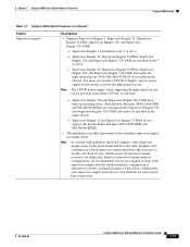
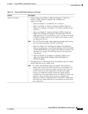
... In systems with the smaller memory configuration is installed in the chassis to power the high-speed fan tray. You must have built-in the same chassis. - Switch Fabric Modules (WS-C6500-SFM and WS-X6500-SFM2) are installed in ...in slot 5 or slot 6. - Supervisor Engine 2 is sufficient to run the configured features of the switch. Chapter 1 Catalyst 6500 Series Switch Chassis Overview Catalyst 6506 Switch Table 1-7 Catalyst 6506 Switch Features (continued) Feature Supervisor engines Descriptions • Supports Supervisor Engine 2, Supervisor Engine 32, Supervisor Engine 32...
... In systems with the smaller memory configuration is installed in the chassis to power the high-speed fan tray. You must have built-in the same chassis. - Switch Fabric Modules (WS-C6500-SFM and WS-X6500-SFM2) are installed in ...in slot 5 or slot 6. - Supervisor Engine 2 is sufficient to run the configured features of the switch. Chapter 1 Catalyst 6500 Series Switch Chassis Overview Catalyst 6506 Switch Table 1-7 Catalyst 6506 Switch Features (continued) Feature Supervisor engines Descriptions • Supports Supervisor Engine 2, Supervisor Engine 32, Supervisor Engine 32...
Installation Guide
Page 35
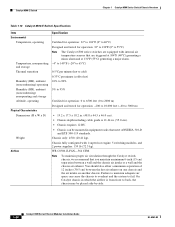
...176; to 40°C) Designed and tested for operation: 32° to 130°F (0° to 55°C) Note The Catalyst 6500 series switches are equipped with 1 supervisor engine, 5 switching modules, and 2 power supplies: 156.6 lb (71.0 kg). • WS-C6K-6SLOT-FAN (Standard fan tray)-227 CFM. • WS-C6K-... cm) separation between the hot air exhaust on one chassis and the air intake on another chassis. Note To maintain proper air circulation through the Catalyst switch chassis, we recommend that meet ANSI/EIA 310-D and ETS 300-119 standards. • Chassis only: 45 lb (20.4 kg). •...
...176; to 40°C) Designed and tested for operation: 32° to 130°F (0° to 55°C) Note The Catalyst 6500 series switches are equipped with 1 supervisor engine, 5 switching modules, and 2 power supplies: 156.6 lb (71.0 kg). • WS-C6K-6SLOT-FAN (Standard fan tray)-227 CFM. • WS-C6K-... cm) separation between the hot air exhaust on one chassis and the air intake on another chassis. Note To maintain proper air circulation through the Catalyst switch chassis, we recommend that meet ANSI/EIA 310-D and ETS 300-119 standards. • Chassis only: 45 lb (20.4 kg). •...
Installation Guide
Page 36
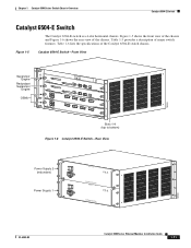
... of the Catalyst 6506-E switch chassis. Table 1-10 lists the specifications of the major switch features. Catalyst 6506-E Switch Chapter 1 Catalyst 6500 Series Switch Chassis Overview Catalyst 6506-E Switch The Catalyst 6506-E switch is a 6-slot horizontal chassis. Figure 1-8 Catalyst 6506-E Switch LINK LINK LINK Switching modules Fan ... o o INPUT OK FAN OUTPUT OK FAIL INPUT OK FAN OUTPUT OK FAIL Power supply 1 Power supply 2 ESD ground strap (redundant) connector 18224 1-20 Catalyst 6500 Series Ethernet Modules Installation Guide OL-6265-03 Figure 1-8 shows a front ...
... of the Catalyst 6506-E switch chassis. Table 1-10 lists the specifications of the major switch features. Catalyst 6506-E Switch Chapter 1 Catalyst 6500 Series Switch Chassis Overview Catalyst 6506-E Switch The Catalyst 6506-E switch is a 6-slot horizontal chassis. Figure 1-8 Catalyst 6506-E Switch LINK LINK LINK Switching modules Fan ... o o INPUT OK FAN OUTPUT OK FAIL INPUT OK FAN OUTPUT OK FAIL Power supply 1 Power supply 2 ESD ground strap (redundant) connector 18224 1-20 Catalyst 6500 Series Ethernet Modules Installation Guide OL-6265-03 Figure 1-8 shows a front ...

Installation Guide
Page 37
... one DC-input. Chapter 1 Catalyst 6500 Series Switch Chassis Overview Catalyst 6506-E Switch Table 1-9 Catalyst 6506-E Switch Features Feature Chassis Power supplies Descriptions Six horizontal slots. The second power supply is installed in the left power supply bay. Slots are numbered from 1 (top) to Appendix A, "Power Supply Specifications," in the Catalyst 6500 Series Switches Installation Guide. • Installed power supplies can be configured...
... one DC-input. Chapter 1 Catalyst 6500 Series Switch Chassis Overview Catalyst 6506-E Switch Table 1-9 Catalyst 6506-E Switch Features Feature Chassis Power supplies Descriptions Six horizontal slots. The second power supply is installed in the left power supply bay. Slots are numbered from 1 (top) to Appendix A, "Power Supply Specifications," in the Catalyst 6500 Series Switches Installation Guide. • Installed power supplies can be configured...
Installation Guide
Page 40
...Installation Guide OL-6265-03 Chassis fully configured with internal air temperature sensors that are equipped with 1 supervisor engine, 5 switching modules, and 2 power supplies: 159 lb (72.3 kg). On Catalyst chassis in equipment racks that you maintain a minimum 6-inch (15 cm) separation between the hot air exhaust on ...(48.8 x 44.5 x 46.0 cm). • Chassis depth including cable guide is from front to fail. Note To maintain proper air circulation through the Catalyst switch chassis, we recommend that meet ANSI/EIA 310-D and ETS 300-119 standards. WS-C6506-E-FAN-564 CFM.
...Installation Guide OL-6265-03 Chassis fully configured with internal air temperature sensors that are equipped with 1 supervisor engine, 5 switching modules, and 2 power supplies: 159 lb (72.3 kg). On Catalyst chassis in equipment racks that you maintain a minimum 6-inch (15 cm) separation between the hot air exhaust on ...(48.8 x 44.5 x 46.0 cm). • Chassis depth including cable guide is from front to fail. Note To maintain proper air circulation through the Catalyst switch chassis, we recommend that meet ANSI/EIA 310-D and ETS 300-119 standards. WS-C6506-E-FAN-564 CFM.

Installation Guide
Page 41
... Power supply 1 Power supply 2 ESD ground strap (redundant) connector 16076 OL-6265-03 Catalyst 6500 Series Ethernet Modules Installation Guide 1-25 Table 1-12 lists the specifications of the major switch features. Table 1-11 provides a description of the Catalyst 6509 switch chassis. Figure 1-9 shows a front view of the chassis. Chapter 1 Catalyst 6500 Series Switch Chassis Overview Catalyst 6509 Switch Catalyst 6509 Switch The Catalyst...
... Power supply 1 Power supply 2 ESD ground strap (redundant) connector 16076 OL-6265-03 Catalyst 6500 Series Ethernet Modules Installation Guide 1-25 Table 1-12 lists the specifications of the major switch features. Table 1-11 provides a description of the Catalyst 6509 switch chassis. Figure 1-9 shows a front view of the chassis. Chapter 1 Catalyst 6500 Series Switch Chassis Overview Catalyst 6509 Switch Catalyst 6509 Switch The Catalyst...

Installation Guide
Page 42
... isolated. • Single power supplies are limited to Appendix A, "Power Supply Specifications," in the Catalyst 6500 Series Switches Installation Guide. • Installed power supplies can be configured in the left power supply bay. WS-CAC-2500W (2500 W AC-input power supply) - Catalyst 6509 Switch Chapter 1 Catalyst 6500 Series Switch Chassis Overview Table 1-11 Catalyst 6509 Switch Features Feature Chassis Power supplies Description Nine horizontal...
... isolated. • Single power supplies are limited to Appendix A, "Power Supply Specifications," in the Catalyst 6500 Series Switches Installation Guide. • Installed power supplies can be configured in the left power supply bay. WS-CAC-2500W (2500 W AC-input power supply) - Catalyst 6509 Switch Chapter 1 Catalyst 6500 Series Switch Chassis Overview Table 1-11 Catalyst 6509 Switch Features Feature Chassis Power supplies Description Nine horizontal...
Installation Guide
Page 43
... the same daughter card configurations. Additionally, each supervisor engine must also install a 2500 W or higher capacity power supply in the chassis to power the high-speed fan tray. Chapter 1 Catalyst 6500 Series Switch Chassis Overview Catalyst 6509 Switch Table 1-11 Catalyst 6509 Switch Features (continued) Feature Supervisor engines Description • Supports Supervisor Engine 2, Supervisor Engine 32, Supervisor Engine...
... the same daughter card configurations. Additionally, each supervisor engine must also install a 2500 W or higher capacity power supply in the chassis to power the high-speed fan tray. Chapter 1 Catalyst 6500 Series Switch Chassis Overview Catalyst 6509 Switch Table 1-11 Catalyst 6509 Switch Features (continued) Feature Supervisor engines Description • Supports Supervisor Engine 2, Supervisor Engine 32, Supervisor Engine...
Installation Guide
Page 45
..., 8 switching modules, and 2 power supplies: 194.5 lb (88.2 kg). • WS-C6K-9SLOT-FAN (Standard fan tray)-340 CFM • WS-C6K-9SLOT-FAN2 (Optional high-speed fan tray)-630 CFM Note To maintain proper air circulation through the Catalyst switch chassis, ...adequate air space can be mounted in which the airflow is from front to fail. Chapter 1 Catalyst 6500 Series Switch Chassis Overview Catalyst 6509 Switch Table 1-12 Catalyst 6509 Switch Specifications Item Environmental Temperature, operating Temperature, ambient nonoperating and storage Thermal transition Humidity (RH), ambient (...
..., 8 switching modules, and 2 power supplies: 194.5 lb (88.2 kg). • WS-C6K-9SLOT-FAN (Standard fan tray)-340 CFM • WS-C6K-9SLOT-FAN2 (Optional high-speed fan tray)-630 CFM Note To maintain proper air circulation through the Catalyst switch chassis, ...adequate air space can be mounted in which the airflow is from front to fail. Chapter 1 Catalyst 6500 Series Switch Chassis Overview Catalyst 6509 Switch Table 1-12 Catalyst 6509 Switch Specifications Item Environmental Temperature, operating Temperature, ambient nonoperating and storage Thermal transition Humidity (RH), ambient (...
