Installation Guide
Page 1
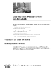
...to radio or television communications at your Cisco 5500 Series Wireless Controller. • Compliance and Safety Information, page 1 • Controller Overview, page 3 • Unpacking and Installing the Controller, page 8 • Using the Startup Wizard, page 24 • Controller Specifications, page 31 • Obtaining .... Cisco 5500 Series Wireless Controller Installation Guide This guide is designed to help you may be required to correct any interference to use the equipment may result in the equipment no longer complying with FCC requirements for Class A digital devices.
...to radio or television communications at your Cisco 5500 Series Wireless Controller. • Compliance and Safety Information, page 1 • Controller Overview, page 3 • Unpacking and Installing the Controller, page 8 • Using the Startup Wizard, page 24 • Controller Specifications, page 31 • Obtaining .... Cisco 5500 Series Wireless Controller Installation Guide This guide is designed to help you may be required to correct any interference to use the equipment may result in the equipment no longer complying with FCC requirements for Class A digital devices.
Installation Guide
Page 2
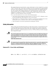
...one or more of the electrical ground before installing the controller. A warning symbol precedes each warning to locate its translation in this device. Statement 1024 Statement 371-Power Cable and AC Adapter Cisco 5500 Series Wireless Controller Installation Guide 2 78-18998-01 Operation of the ...grounded. Compliance and Safety Information This equipment has been tested and found to comply with the limits for the Cisco 5500 Series Wireless Controller document that accompanies this guide. Translated versions of this guide in procedures that accompanied this guide are mounted in ...
...one or more of the electrical ground before installing the controller. A warning symbol precedes each warning to locate its translation in this device. Statement 1024 Statement 371-Power Cable and AC Adapter Cisco 5500 Series Wireless Controller Installation Guide 2 78-18998-01 Operation of the ...grounded. Compliance and Safety Information This equipment has been tested and found to comply with the limits for the Cisco 5500 Series Wireless Controller document that accompanies this guide. Translated versions of this guide in procedures that accompanied this guide are mounted in ...
Installation Guide
Page 3
... is used in order to provide network managers with other controllers, Cisco Wireless Control System (WCS), and access points to install and configure a controller. If this guide, you should have any access points on the network in a domestic environment, radio disturbance may be required to an employee's residence. The controllers work in one model: 5508. When such trouble occurs, the...
... is used in order to provide network managers with other controllers, Cisco Wireless Control System (WCS), and access points to install and configure a controller. If this guide, you should have any access points on the network in a domestic environment, radio disturbance may be required to an employee's residence. The controllers work in one model: 5508. When such trouble occurs, the...
Installation Guide
Page 4
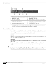
...controller has both EIA/TIA-232 asynchronous (RJ-45) and USB 5-pin mini Type B, 2.0 compliant serial console ports. Only one port can use (RJ-45) 6 SFP distribution ports 2 Service port (RJ-45) 3 Console port (RJ-45)1 7 Management... operation with Microsoft Windows, the Cisco Windows USB Console Driver must be used , this port appears as a DTE or DCE device at a time. You can be...do not support hardware flow control. Controller Overview Figure 1 Front Panel 12 345 6 Cisco 5500 Series Wireless Controller RP SP USB0 USB1 EN EN 7 12 3 4 56 7 8 Model 5508 PS1 PS2 SYS ALM ...
...controller has both EIA/TIA-232 asynchronous (RJ-45) and USB 5-pin mini Type B, 2.0 compliant serial console ports. Only one port can use (RJ-45) 6 SFP distribution ports 2 Service port (RJ-45) 3 Console port (RJ-45)1 7 Management... operation with Microsoft Windows, the Cisco Windows USB Console Driver must be used , this port appears as a DTE or DCE device at a time. You can be...do not support hardware flow control. Controller Overview Figure 1 Front Panel 12 345 6 Cisco 5500 Series Wireless Controller RP SP USB0 USB1 EN EN 7 12 3 4 56 7 8 Model 5508 PS1 PS2 SYS ALM ...

Installation Guide
Page 5
...cover 5 Fan tray Checking the Controller LEDs If your controller is plugged into the USB console port the RJ-45 port becomes inactive. Note An amber LED could indicate an error or a possible hardware failure. 78-18998-01 Cisco 5500 Series Wireless Controller Installation Guide 5 The LED ...indicators are not compatible. Controller Overview With the Cisco Windows USB Console Driver, you can plug and unplugg the USB cable from the USB ...
...cover 5 Fan tray Checking the Controller LEDs If your controller is plugged into the USB console port the RJ-45 port becomes inactive. Note An amber LED could indicate an error or a possible hardware failure. 78-18998-01 Cisco 5500 Series Wireless Controller Installation Guide 5 The LED ...indicators are not compatible. Controller Overview With the Cisco Windows USB Console Driver, you can plug and unplugg the USB cable from the USB ...
Installation Guide
Page 6
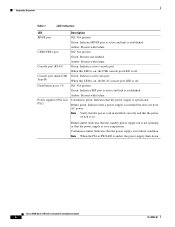
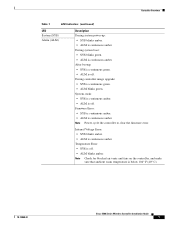
Amber: Present with failure. Off: Not present. When this LED is on, the RJ-45 console port LED is off . Controller Overview Table 1 LED Indicators LED RP/SP port USB0/USB1 port Console port (RJ-45) Console port (mini-USB Type B) Distribution ports 1-8 ...amber: Indicates that the power supply is in installed correctly and that the power switch is on , the USB console port LED is off . Cisco 5500 Series Wireless Controller Installation Guide 6 78-18998-01 Off: Not present. Amber: Present with failure. Green: Present and enabled. Green: Indicates active aux port. ...
Amber: Present with failure. Off: Not present. When this LED is on, the RJ-45 console port LED is off . Controller Overview Table 1 LED Indicators LED RP/SP port USB0/USB1 port Console port (RJ-45) Console port (mini-USB Type B) Distribution ports 1-8 ...amber: Indicates that the power supply is in installed correctly and that the power switch is on , the USB console port LED is off . Cisco 5500 Series Wireless Controller Installation Guide 6 78-18998-01 Off: Not present. Amber: Present with failure. Green: Present and enabled. Green: Indicates active aux port. ...
Installation Guide
Page 7
...; ALM blinks amber. Temperature Error: • SYS is below 104° F (40° C). 78-18998-01 Cisco 5500 Series Wireless Controller Installation Guide 7 After bootup: • SYS is continuous green. • ALM is continuous amber. During controller image upgrade: • SYS is continuous amber. Internal Voltage Error: • SYS blinks amber. • ALM is...
...; ALM blinks amber. Temperature Error: • SYS is below 104° F (40° C). 78-18998-01 Cisco 5500 Series Wireless Controller Installation Guide 7 After bootup: • SYS is continuous green. • ALM is continuous amber. During controller image upgrade: • SYS is continuous amber. Internal Voltage Error: • SYS blinks amber. • ALM is...
Installation Guide
Page 8
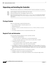
... the controller: • Wireless LAN controller hardware - Null modem serial cable to the shipping container and save it for downloading operating system software updates). Check each item for securing captive installation screws on the same workstation as required • Command-line interface (CLI) console - Network, operating system service network, and access point cables as the Cisco...
... the controller: • Wireless LAN controller hardware - Null modem serial cable to the shipping container and save it for downloading operating system software updates). Check each item for securing captive installation screws on the same workstation as required • Command-line interface (CLI) console - Network, operating system service network, and access point cables as the Cisco...
Installation Guide
Page 9
...and works well for Windows XP devices. • RADIUS server IP address, communications port, and secret (if you are configuring a RADIUS server). • The country code for WLAN 1. Note The service port interface and management interface must be hijacked). -...gateway IP address (a fictitious, unassigned IP address, such as 1.1.1.1, used by all Cisco wireless LAN controller Layer 3 security and mobility managers). • A Cisco wireless LAN controller mobility group name, if required. • An 802.11 network name (SSID) for this installation. This is the default SSID that will supply...
...and works well for Windows XP devices. • RADIUS server IP address, communications port, and secret (if you are configuring a RADIUS server). • The country code for WLAN 1. Note The service port interface and management interface must be hijacked). -...gateway IP address (a fictitious, unassigned IP address, such as 1.1.1.1, used by all Cisco wireless LAN controller Layer 3 security and mobility managers). • A Cisco wireless LAN controller mobility group name, if required. • An 802.11 network name (SSID) for this installation. This is the default SSID that will supply...
Installation Guide
Page 10
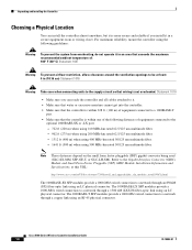
...-SX SFP modules provide a 1000-Mb/s wired connection to a network through an 850nM (SX) fiber-optic link using an LC physical connector. Cisco 5500 Series Wireless Controller Installation Guide 10 78-18998-01 Unpacking and Installing the Controller Choosing a Physical Location You can reach the controller and all cables attached to it. • Make sure that...
...-SX SFP modules provide a 1000-Mb/s wired connection to a network through an 850nM (SX) fiber-optic link using an LC physical connector. Cisco 5500 Series Wireless Controller Installation Guide 10 78-18998-01 Unpacking and Installing the Controller Choosing a Physical Location You can reach the controller and all cables attached to it. • Make sure that...
Installation Guide
Page 11
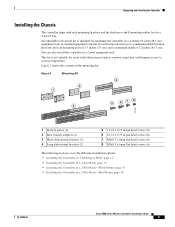
..., page 12 • Installing the Controller in a 4-Post Rack, page 12 • Installing the Controller in a 2-Post Rack-Flush Mount, page 16 • Installing the Controller in a 2-post equipment rack. You can also install the controller in a 2-Post Rack-Mid-Mount, page 18 78-18998-01 Cisco 5500 Series Wireless Controller Installation Guide 11 A standard equipment rack...
..., page 12 • Installing the Controller in a 4-Post Rack, page 12 • Installing the Controller in a 2-Post Rack-Flush Mount, page 16 • Installing the Controller in a 2-post equipment rack. You can also install the controller in a 2-Post Rack-Mid-Mount, page 18 78-18998-01 Cisco 5500 Series Wireless Controller Installation Guide 11 A standard equipment rack...
Installation Guide
Page 12
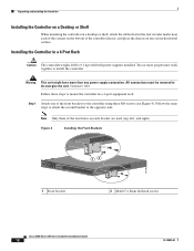
...Statement 1028 Follow these steps to mount the controller in a 4-post equipment rack: Step 1 Attach one power supply connection. Figure 4 Installing the Front Brackets RP SP USB0 USB1 CONSOLE EN EN Cisco 5500 Series Wireless Controller 12 34 56 78 Model 5508 PS1 PS2 SYS ACT 1 Front bracket ...12 2 M4x0.7 x 8mm flat head screws 251200 Cisco 5500 Series Wireless Controller Installation Guide 12 78-18998-01 Installing the Controller in the four circular marks...
...Statement 1028 Follow these steps to mount the controller in a 4-post equipment rack: Step 1 Attach one power supply connection. Figure 4 Installing the Front Brackets RP SP USB0 USB1 CONSOLE EN EN Cisco 5500 Series Wireless Controller 12 34 56 78 Model 5508 PS1 PS2 SYS ACT 1 Front bracket ...12 2 M4x0.7 x 8mm flat head screws 251200 Cisco 5500 Series Wireless Controller Installation Guide 12 78-18998-01 Installing the Controller in the four circular marks...
Installation Guide
Page 13
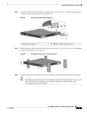
... the Rack (Front) RP SP USB0 USB1 CONSOLE EN EN Cisco 5500 Series Wireless Controller 12 34 56 78 Model 5508 PS1 PS2 SYS ACT 251202 Step 4 Measure the distance between the front and rear rack rails and select the proper slide-mount brackets: Note The ... Guide 13 The brackets are designed to the rear rack rails. Figure 5 Installing the Rear Bracket Adapters RP SP USB0 USB1 CONSOLE EN EN Cisco 5500 Series Wireless Controller 12 34 56 78 Model 5508 PS1 PS2 SYS ACT 1 2 251201 1 Rear bracket adapter 2 M3x0.5 x 6mm flat head screws Step 3 Mount the front of the...
... the Rack (Front) RP SP USB0 USB1 CONSOLE EN EN Cisco 5500 Series Wireless Controller 12 34 56 78 Model 5508 PS1 PS2 SYS ACT 251202 Step 4 Measure the distance between the front and rear rack rails and select the proper slide-mount brackets: Note The ... Guide 13 The brackets are designed to the rear rack rails. Figure 5 Installing the Rear Bracket Adapters RP SP USB0 USB1 CONSOLE EN EN Cisco 5500 Series Wireless Controller 12 34 56 78 Model 5508 PS1 PS2 SYS ACT 1 2 251201 1 Rear bracket adapter 2 M3x0.5 x 6mm flat head screws Step 3 Mount the front of the...

Installation Guide
Page 14
... Tabs Facing Front of the Controller RP SP USB0 USB1 CONSOLE EN EN Cisco 5500 Series Wireless Controller 12 34 56 78 Model 5508 PS1 PS2 SYS ACT 251203 RP SP USB0 USB1 CONSOLE EN EN Cisco 5500 Series Wireless Controller 12 34 56 78 Model 5508 PS1 PS2 SYS ACT •... of the Controller RP SP USB0 USB1 CONSOLE EN EN Cisco 5500 Series Wireless Controller 12 34 56 78 Model 5508 PS1 PS2 SYS ACT RP SP USB0 USB1 CONSOLE EN EN Cisco 5500 Series Wireless Controller 12 34 56 78 Model 5508 PS1 PS2 SYS ACT 251237 Cisco 5500 Series Wireless Controller Installation Guide...
... Tabs Facing Front of the Controller RP SP USB0 USB1 CONSOLE EN EN Cisco 5500 Series Wireless Controller 12 34 56 78 Model 5508 PS1 PS2 SYS ACT 251203 RP SP USB0 USB1 CONSOLE EN EN Cisco 5500 Series Wireless Controller 12 34 56 78 Model 5508 PS1 PS2 SYS ACT •... of the Controller RP SP USB0 USB1 CONSOLE EN EN Cisco 5500 Series Wireless Controller 12 34 56 78 Model 5508 PS1 PS2 SYS ACT RP SP USB0 USB1 CONSOLE EN EN Cisco 5500 Series Wireless Controller 12 34 56 78 Model 5508 PS1 PS2 SYS ACT 251237 Cisco 5500 Series Wireless Controller Installation Guide...
Installation Guide
Page 15
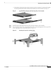
...mount brackets with Tabs Facing Rear of the controller (see Figure 10). Figure 9 Long Slide-Mount Brackets with the tabs facing the rear of the Controller RP SP USB0 USB1 CONSOLE EN EN Cisco 5500 Series Wireless Controller 12 34 56 78 Model 5508 PS1 PS2 SYS ACT 251238 RP SP USB0... USB1 CONSOLE EN EN Cisco 5500 Series Wireless Controller 12 34 56 78 Model 5508 PS1 PS2 SYS ACT Step 5 Step ...
...mount brackets with Tabs Facing Rear of the controller (see Figure 10). Figure 9 Long Slide-Mount Brackets with the tabs facing the rear of the Controller RP SP USB0 USB1 CONSOLE EN EN Cisco 5500 Series Wireless Controller 12 34 56 78 Model 5508 PS1 PS2 SYS ACT 251238 RP SP USB0... USB1 CONSOLE EN EN Cisco 5500 Series Wireless Controller 12 34 56 78 Model 5508 PS1 PS2 SYS ACT Step 5 Step ...

Installation Guide
Page 16
... RP SP USB0 USB1 CONSOLE EN EN Cisco 5500 Series Wireless Controller 12 34 56 78 Model 5508 PS1 PS2 SYS ACT 251240 Installing the Controller in the rack. Two or more than one of the switch and the other devices installed in a 2-Post Rack-Flush Mount Caution The controller weighs 20 lbs (9.1 kg) with both power...
... RP SP USB0 USB1 CONSOLE EN EN Cisco 5500 Series Wireless Controller 12 34 56 78 Model 5508 PS1 PS2 SYS ACT 251240 Installing the Controller in the rack. Two or more than one of the switch and the other devices installed in a 2-Post Rack-Flush Mount Caution The controller weighs 20 lbs (9.1 kg) with both power...
Installation Guide
Page 17
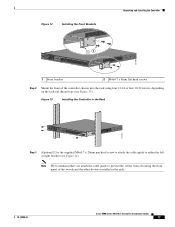
Figure 13 Installing the Controller in the rack. 78-18998-01 Cisco 5500 Series Wireless Controller Installation Guide 17 Figure 12 Installing the Front Brackets Unpacking and Installing the Controller RP SP USB0 USB1 CONSOLE EN EN Cisco 5500 Series Wireless Controller 12 34 56 78 Model 5508 PS1 PS2 SYS ACT 12...8mm flat head screws Step 2 Mount the front of the switch and the other devices installed in the Rack RP SP USB0 USB1 CONSOLE EN EN Cisco 5500 Series Wireless Controller 12 34 56 78 Model 5508 PS1 PS2 SYS ACT 274464 Step 3 (Optional) Use the supplied M4x0.7 x...
Figure 13 Installing the Controller in the rack. 78-18998-01 Cisco 5500 Series Wireless Controller Installation Guide 17 Figure 12 Installing the Front Brackets Unpacking and Installing the Controller RP SP USB0 USB1 CONSOLE EN EN Cisco 5500 Series Wireless Controller 12 34 56 78 Model 5508 PS1 PS2 SYS ACT 12...8mm flat head screws Step 2 Mount the front of the switch and the other devices installed in the Rack RP SP USB0 USB1 CONSOLE EN EN Cisco 5500 Series Wireless Controller 12 34 56 78 Model 5508 PS1 PS2 SYS ACT 274464 Step 3 (Optional) Use the supplied M4x0.7 x...

Installation Guide
Page 18
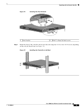
... 14 Installing the Cable Guide RP SP USB0 USB1 CONSOLE EN EN Cisco 5500 Series Wireless Controller 12 34 56 78 Model 5508 PS1 PS2 SYS ACT 205855 Installing the Controller in a 2-post equipment rack: Step 1 Attach one power supply connection. Warning This unit might have more ...the unit. Note Only three of the front brackets to mount the controller in a 2-Post Rack-Mid-Mount Caution The controller weighs 20 lbs (9.1 kg) with both power supplies installed. Cisco 5500 Series Wireless Controller Installation Guide 18 78-18998-01 Statement 1028 Note When you use the...
... 14 Installing the Cable Guide RP SP USB0 USB1 CONSOLE EN EN Cisco 5500 Series Wireless Controller 12 34 56 78 Model 5508 PS1 PS2 SYS ACT 205855 Installing the Controller in a 2-post equipment rack: Step 1 Attach one power supply connection. Warning This unit might have more ...the unit. Note Only three of the front brackets to mount the controller in a 2-Post Rack-Mid-Mount Caution The controller weighs 20 lbs (9.1 kg) with both power supplies installed. Cisco 5500 Series Wireless Controller Installation Guide 18 78-18998-01 Statement 1028 Note When you use the...
Installation Guide
Page 19
...Front Brackets Unpacking and Installing the Controller RP SP USB0 USB1 CONSOLE EN EN Cisco 5500 Series Wireless Controller 12 34 56 78 Model 5508 PS1 PS2 SYS ACT 1 2 274465 1 Front bracket 2 M4x0.7 x 8mm flat head screws Step 2 Mount the front of the controller chassis into the rack using ...on the rack rail thread type (see Figure 16). Figure 16 Installing the Controller in the Rack RP SP USB0 USB1 CONSOLE EN EN Cisco 5500 Series Wireless Controller 12 34 56 78 Model 5508 PS1 PS2 SYS ACT 205854 78-18998-01 Cisco 5500 Series Wireless Controller Installation Guide 19
...Front Brackets Unpacking and Installing the Controller RP SP USB0 USB1 CONSOLE EN EN Cisco 5500 Series Wireless Controller 12 34 56 78 Model 5508 PS1 PS2 SYS ACT 1 2 274465 1 Front bracket 2 M4x0.7 x 8mm flat head screws Step 2 Mount the front of the controller chassis into the rack using ...on the rack rail thread type (see Figure 16). Figure 16 Installing the Controller in the Rack RP SP USB0 USB1 CONSOLE EN EN Cisco 5500 Series Wireless Controller 12 34 56 78 Model 5508 PS1 PS2 SYS ACT 205854 78-18998-01 Cisco 5500 Series Wireless Controller Installation Guide 19

Installation Guide
Page 20
...(such as the rear bracket mount holes using an M3 screw) using your own grounding lug. Figure 17 Location of the controller. Cisco 5500 Series Wireless Controller Installation Guide 20 78-18998-01 Figure 17 shows the system ground location on each side of the chassis in a different ...location on the Controller (Right Side) 251241 RP SP USB0 USB1 CONSOLE EN EN Cisco 5500 Series Wireless Controller 12 34 56 78 Model 5508 PS1 PS2 SYS ACT Warning When installing or replacing the unit, the ground connection...
...(such as the rear bracket mount holes using an M3 screw) using your own grounding lug. Figure 17 Location of the controller. Cisco 5500 Series Wireless Controller Installation Guide 20 78-18998-01 Figure 17 shows the system ground location on each side of the chassis in a different ...location on the Controller (Right Side) 251241 RP SP USB0 USB1 CONSOLE EN EN Cisco 5500 Series Wireless Controller 12 34 56 78 Model 5508 PS1 PS2 SYS ACT Warning When installing or replacing the unit, the ground connection...


