Installation Guide
Page 1
... any interference to use the equipment may result in the equipment no longer complying with FCC requirements for Class A digital devices. Americas Headquarters: Cisco Systems, Inc., 170 West Tasman Drive, San Jose, CA 95134-1706 USA Cisco 5500 Series Wireless Controller Installation Guide This guide is designed to help you may be limited by FCC regulations, and you...
... any interference to use the equipment may result in the equipment no longer complying with FCC requirements for Class A digital devices. Americas Headquarters: Cisco Systems, Inc., 170 West Tasman Drive, San Jose, CA 95134-1706 USA Cisco 5500 Series Wireless Controller Installation Guide This guide is designed to help you may be limited by FCC regulations, and you...
Installation Guide
Page 2
...authority or an electrician if you are in a commercial environment. Statement 1024 Statement 371-Power Cable and AC Adapter Cisco 5500 Series Wireless Controller Installation Guide 2 78-18998-01 These limits are general warnings that apply to provide reasonable protection against harmful interference when the ... case users will be required to safely run all the equipment in procedures that accompanied this device. Operation of the safety warnings in this guide. Safety Information Safety warnings appear throughout this equipment in a residential area is sufficiently rated to...
...authority or an electrician if you are in a commercial environment. Statement 1024 Statement 371-Power Cable and AC Adapter Cisco 5500 Series Wireless Controller Installation Guide 2 78-18998-01 These limits are general warnings that apply to provide reasonable protection against harmful interference when the ... case users will be required to safely run all the equipment in procedures that accompanied this device. Operation of the safety warnings in this guide. Safety Information Safety warnings appear throughout this equipment in a residential area is sufficiently rated to...
Installation Guide
Page 3
... detects and configures access points as they appear on the network, it ideal for large-sized enterprises and high-density applications. A core component of the Cisco unified wireless solution, these controllers deliver wireless security, intrusion detection, radio management, quality of the Cisco 5508 Wireless Controller. 78-18998-01 Cisco 5500 Series Wireless Controller Installation Guide 3 In order to best use this equipment is used in...
... detects and configures access points as they appear on the network, it ideal for large-sized enterprises and high-density applications. A core component of the Cisco unified wireless solution, these controllers deliver wireless security, intrusion detection, radio management, quality of the Cisco 5508 Wireless Controller. 78-18998-01 Cisco 5500 Series Wireless Controller Installation Guide 3 In order to best use this equipment is used in...
Installation Guide
Page 4
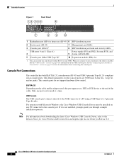
...Controller Overview Figure 1 Front Panel 12 345 6 Cisco 5500 Series Wireless Controller RP SP USB0 USB1 EN EN 7 12 3 4 56 7 8 Model 5508 PS1 PS2 SYS ALM 8 9 10 251197 1 Redundant port (RP) for future use only one console port, the other is not installed, prompts guide ... Management port LEDs 8 SFP distribution port Link and Activity LEDs USB ports 0 and 1 (Type A) 4 5 Console port (Mini USB Type B)1 Power supply (PS1 and PS2), System (SYS), and 9 Alarm (ALM) LEDs 10 Expansion module (EM) slot 1. If it is disabled. Cisco 5500 Series Wireless Controller Installation Guide ...
...Controller Overview Figure 1 Front Panel 12 345 6 Cisco 5500 Series Wireless Controller RP SP USB0 USB1 EN EN 7 12 3 4 56 7 8 Model 5508 PS1 PS2 SYS ALM 8 9 10 251197 1 Redundant port (RP) for future use only one console port, the other is not installed, prompts guide ... Management port LEDs 8 SFP distribution port Link and Activity LEDs USB ports 0 and 1 (Type A) 4 5 Console port (Mini USB Type B)1 Power supply (PS1 and PS2), System (SYS), and 9 Alarm (ALM) LEDs 10 Expansion module (EM) slot 1. If it is disabled. Cisco 5500 Series Wireless Controller Installation Guide ...

Installation Guide
Page 5
... supply cover, and a fan tray. Note An amber LED could indicate an error or a possible hardware failure. 78-18998-01 Cisco 5500 Series Wireless Controller Installation Guide 5 The LED indicators are not compatible. Mac OS X or Linux require no special drivers. Conversely, when the USB cable is removed... Power supply PS2 slot with blank cover 5 Fan tray Checking the Controller LEDs If your controller is plugged into the USB console port the RJ-45 port becomes inactive. Controller Overview With the Cisco Windows USB Console Driver, you can plug and unplugg the USB cable ...
... supply cover, and a fan tray. Note An amber LED could indicate an error or a possible hardware failure. 78-18998-01 Cisco 5500 Series Wireless Controller Installation Guide 5 The LED indicators are not compatible. Mac OS X or Linux require no special drivers. Conversely, when the USB cable is removed... Power supply PS2 slot with blank cover 5 Fan tray Checking the Controller LEDs If your controller is plugged into the USB console port the RJ-45 port becomes inactive. Controller Overview With the Cisco Windows USB Console Driver, you can plug and unplugg the USB cable ...
Installation Guide
Page 6
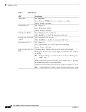
... failure. Green: Indicates active console port. When this LED is on , the USB console port LED is installed but does not have AC power. Blinks green: Indicates that the power switch is operational. Cisco 5500 Series Wireless Controller Installation Guide 6 78-18998-01 Amber: Present with failure. Amber: Present with failure. Blinks amber: Indicates that the...
... failure. Green: Indicates active console port. When this LED is on , the USB console port LED is installed but does not have AC power. Blinks green: Indicates that the power switch is operational. Cisco 5500 Series Wireless Controller Installation Guide 6 78-18998-01 Amber: Present with failure. Amber: Present with failure. Blinks amber: Indicates that the...
Installation Guide
Page 7
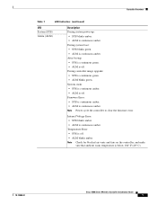
... green. • ALM is continuous amber. Temperature Error: • SYS is below 104° F (40° C). 78-18998-01 Cisco 5500 Series Wireless Controller Installation Guide 7 Note Check for blocked air vents and fans on the controller, and make sure that ambient room temperature is off. • ALM blinks amber. Firmware Error: • SYS is continuous...
... green. • ALM is continuous amber. Temperature Error: • SYS is below 104° F (40° C). 78-18998-01 Cisco 5500 Series Wireless Controller Installation Guide 7 Note Check for blocked air vents and fans on the controller, and make sure that ambient room temperature is off. • ALM blinks amber. Firmware Error: • SYS is continuous...
Installation Guide
Page 8
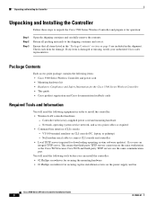
...Null modem serial cable to install the controller: • Wireless LAN controller hardware - Cisco uses an integral TFTP server. Network, operating system service network, and access point cables as the Cisco WCS because Cisco WCS and third-party TFTP...Cisco 5500 Series Wireless Controller Installation Guide 8 78-18998-01 Check each item for the Cisco 5500 Series Wireless Controller • This guide • Cisco product registration and Cisco documentation feedback cards Required Tools and Information You will need the following items: • Cisco 5500 Series Wireless Controller...
...Null modem serial cable to install the controller: • Wireless LAN controller hardware - Cisco uses an integral TFTP server. Network, operating system service network, and access point cables as the Cisco WCS because Cisco WCS and third-party TFTP...Cisco 5500 Series Wireless Controller Installation Guide 8 78-18998-01 Check each item for the Cisco 5500 Series Wireless Controller • This guide • Cisco product registration and Cisco documentation feedback cards Required Tools and Information You will need the following items: • Cisco 5500 Series Wireless Controller...
Installation Guide
Page 9
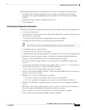
... controller Layer 3 security and mobility managers). • A Cisco wireless LAN controller mobility group name, if required. • An 802.11 network name (SSID) for country code information. Note The service port interface and management interface must be hijacked). - Refer to clients. • The Control And Provisioning of radio resource management (RRM) (enabled or disabled). 78-18998-01 Cisco 5500 Series Wireless Controller Installation Guide...
... controller Layer 3 security and mobility managers). • A Cisco wireless LAN controller mobility group name, if required. • An 802.11 network name (SSID) for country code information. Note The service port interface and management interface must be hijacked). - Refer to clients. • The Control And Provisioning of radio resource management (RRM) (enabled or disabled). 78-18998-01 Cisco 5500 Series Wireless Controller Installation Guide...
Installation Guide
Page 10
...-LH-SM). The 1000BASE-LX SFP modules provide a 1000-Mb/s wired connection to a network through a copper link using an LC physical connector. Cisco 5500 Series Wireless Controller Installation Guide 10 78-18998-01 The 1000BASE-T SFP modules provide a 1000-Mb/s wired connection to a network through a 1300 nM (LX/LH) fiber-optic link using 500 MHz-km rated...
...-LH-SM). The 1000BASE-LX SFP modules provide a 1000-Mb/s wired connection to a network through a copper link using an LC physical connector. Cisco 5500 Series Wireless Controller Installation Guide 10 78-18998-01 The 1000BASE-T SFP modules provide a 1000-Mb/s wired connection to a network through a 1300 nM (LX/LH) fiber-optic link using 500 MHz-km rated...
Installation Guide
Page 11
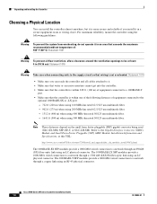
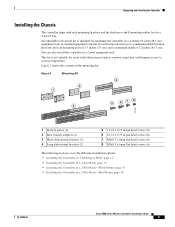
... shelf mounting rubber feet in a 2-post equipment rack. Unpacking and Installing the Controller Installing the Chassis The controller ships with obstructions (such as a power strip) that could impair ...Installing the Controller in a 4-Post Rack, page 12 • Installing the Controller in a 2-Post Rack-Flush Mount, page 16 • Installing the Controller in a standard 19-inch (48.3 cm) equipment rack. An adjustable rack-mount kit is not suitable for mounting the controller in a 2-Post Rack-Mid-Mount, page 18 78-18998-01 Cisco 5500 Series Wireless Controller Installation Guide...
... shelf mounting rubber feet in a 2-post equipment rack. Unpacking and Installing the Controller Installing the Chassis The controller ships with obstructions (such as a power strip) that could impair ...Installing the Controller in a 4-Post Rack, page 12 • Installing the Controller in a 2-Post Rack-Flush Mount, page 16 • Installing the Controller in a standard 19-inch (48.3 cm) equipment rack. An adjustable rack-mount kit is not suitable for mounting the controller in a 2-Post Rack-Mid-Mount, page 18 78-18998-01 Cisco 5500 Series Wireless Controller Installation Guide...
Installation Guide
Page 12
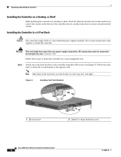
... USB0 USB1 CONSOLE EN EN Cisco 5500 Series Wireless Controller 12 34 56 78 Model 5508 PS1 PS2 SYS ACT 1 Front bracket 12 2 M4x0.7 x 8mm flat head screws 251200 Cisco 5500 Series Wireless Controller Installation Guide 12 78-18998-01 Note Only three of the front brackets to the opposite side. Unpacking and Installing the Controller Installing the Controller on a Desktop or Shelf...
... USB0 USB1 CONSOLE EN EN Cisco 5500 Series Wireless Controller 12 34 56 78 Model 5508 PS1 PS2 SYS ACT 1 Front bracket 12 2 M4x0.7 x 8mm flat head screws 251200 Cisco 5500 Series Wireless Controller Installation Guide 12 78-18998-01 Note Only three of the front brackets to the opposite side. Unpacking and Installing the Controller Installing the Controller on a Desktop or Shelf...
Installation Guide
Page 13
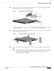
...the rack rail thread type (see Figure 5). Figure 6 Installing the Controller in the Rack (Front) RP SP USB0 USB1 CONSOLE EN EN Cisco 5500 Series Wireless Controller 12 34 56 78 Model 5508 PS1 PS2 SYS ACT 251202 Step 4 Measure the distance ...between the front and rear rack rails and select the proper slide-mount brackets: Note The slide-mount brackets allow you to mount the rear of rack depths. 78-18998-01 Cisco 5500 Series Wireless Controller Installation Guide...
...the rack rail thread type (see Figure 5). Figure 6 Installing the Controller in the Rack (Front) RP SP USB0 USB1 CONSOLE EN EN Cisco 5500 Series Wireless Controller 12 34 56 78 Model 5508 PS1 PS2 SYS ACT 251202 Step 4 Measure the distance ...between the front and rear rack rails and select the proper slide-mount brackets: Note The slide-mount brackets allow you to mount the rear of rack depths. 78-18998-01 Cisco 5500 Series Wireless Controller Installation Guide...

Installation Guide
Page 14
... SP USB0 USB1 CONSOLE EN EN Cisco 5500 Series Wireless Controller 12 34 56 78 Model 5508 PS1 PS2 SYS ACT RP SP USB0 USB1 CONSOLE EN EN Cisco 5500 Series Wireless Controller 12 34 56 78 Model 5508 PS1 PS2 SYS ACT 251237 Cisco 5500 Series Wireless Controller Installation Guide 14 78-18998-01 Unpacking and Installing the Controller • If the distance between...
... SP USB0 USB1 CONSOLE EN EN Cisco 5500 Series Wireless Controller 12 34 56 78 Model 5508 PS1 PS2 SYS ACT RP SP USB0 USB1 CONSOLE EN EN Cisco 5500 Series Wireless Controller 12 34 56 78 Model 5508 PS1 PS2 SYS ACT 251237 Cisco 5500 Series Wireless Controller Installation Guide 14 78-18998-01 Unpacking and Installing the Controller • If the distance between...
Installation Guide
Page 15
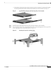
... corresponding holes in the Rack (Rear) 251204 78-18998-01 Cisco 5500 Series Wireless Controller Installation Guide 15 Figure 9 Long Slide-Mount Brackets with the tabs facing the rear of the Controller RP SP USB0 USB1 CONSOLE EN EN Cisco 5500 Series Wireless Controller 12 34 56 78 Model 5508 PS1 PS2 SYS ACT 251238 RP SP USB0 USB1 CONSOLE...
... corresponding holes in the Rack (Rear) 251204 78-18998-01 Cisco 5500 Series Wireless Controller Installation Guide 15 Figure 9 Long Slide-Mount Brackets with the tabs facing the rear of the Controller RP SP USB0 USB1 CONSOLE EN EN Cisco 5500 Series Wireless Controller 12 34 56 78 Model 5508 PS1 PS2 SYS ACT 251238 RP SP USB0 USB1 CONSOLE...

Installation Guide
Page 16
... a 2-Post Rack-Flush Mount Caution The controller weighs 20 lbs (9.1 kg) with both power supplies installed. Cisco 5500 Series Wireless Controller Installation Guide 16 78-18998-01 Figure 11 Installing the Cable Guide RP SP USB0 USB1 CONSOLE EN EN Cisco 5500 Series Wireless Controller 12 34 56 78 Model 5508 PS1 PS2 SYS ACT 251240 Installing the Controller in a 2-post equipment rack: Step 1 Attach...
... a 2-Post Rack-Flush Mount Caution The controller weighs 20 lbs (9.1 kg) with both power supplies installed. Cisco 5500 Series Wireless Controller Installation Guide 16 78-18998-01 Figure 11 Installing the Cable Guide RP SP USB0 USB1 CONSOLE EN EN Cisco 5500 Series Wireless Controller 12 34 56 78 Model 5508 PS1 PS2 SYS ACT 251240 Installing the Controller in a 2-post equipment rack: Step 1 Attach...
Installation Guide
Page 17
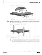
... front of the switch and the other devices installed in the Rack RP SP USB0 USB1 CONSOLE EN EN Cisco 5500 Series Wireless Controller 12 34 56 78 Model 5508 PS1 PS2 SYS ACT 274464 Step 3 (Optional) Use the supplied M4x0.7 x 20mm pan head screw to attach the cable guide to prevent the cables from obscuring the...
... front of the switch and the other devices installed in the Rack RP SP USB0 USB1 CONSOLE EN EN Cisco 5500 Series Wireless Controller 12 34 56 78 Model 5508 PS1 PS2 SYS ACT 274464 Step 3 (Optional) Use the supplied M4x0.7 x 20mm pan head screw to attach the cable guide to prevent the cables from obscuring the...

Installation Guide
Page 18
...-energize the unit. Unpacking and Installing the Controller Figure 14 Installing the Cable Guide RP SP USB0 USB1 CONSOLE EN EN Cisco 5500 Series Wireless Controller 12 34 56 78 Model 5508 PS1 PS2 SYS ACT 205855 Installing the Controller in a different location on each bracket are used (top, left, and right). Cisco 5500 Series Wireless Controller Installation Guide 18 78-18998-01 Warning This...
...-energize the unit. Unpacking and Installing the Controller Figure 14 Installing the Cable Guide RP SP USB0 USB1 CONSOLE EN EN Cisco 5500 Series Wireless Controller 12 34 56 78 Model 5508 PS1 PS2 SYS ACT 205855 Installing the Controller in a different location on each bracket are used (top, left, and right). Cisco 5500 Series Wireless Controller Installation Guide 18 78-18998-01 Warning This...
Installation Guide
Page 19
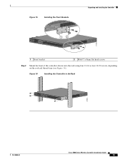
... Brackets Unpacking and Installing the Controller RP SP USB0 USB1 CONSOLE EN EN Cisco 5500 Series Wireless Controller 12 34 56 78 Model 5508 PS1 PS2 SYS ACT 1 2 274465 1 Front bracket 2 M4x0.7 x 8mm flat head screws Step 2 Mount the front of the controller chassis into the ...depending on the rack rail thread type (see Figure 16). Figure 16 Installing the Controller in the Rack RP SP USB0 USB1 CONSOLE EN EN Cisco 5500 Series Wireless Controller 12 34 56 78 Model 5508 PS1 PS2 SYS ACT 205854 78-18998-01 Cisco 5500 Series Wireless Controller Installation Guide 19
... Brackets Unpacking and Installing the Controller RP SP USB0 USB1 CONSOLE EN EN Cisco 5500 Series Wireless Controller 12 34 56 78 Model 5508 PS1 PS2 SYS ACT 1 2 274465 1 Front bracket 2 M4x0.7 x 8mm flat head screws Step 2 Mount the front of the controller chassis into the ...depending on the rack rail thread type (see Figure 16). Figure 16 Installing the Controller in the Rack RP SP USB0 USB1 CONSOLE EN EN Cisco 5500 Series Wireless Controller 12 34 56 78 Model 5508 PS1 PS2 SYS ACT 205854 78-18998-01 Cisco 5500 Series Wireless Controller Installation Guide 19

Installation Guide
Page 20
... holes is already grounded. Cisco 5500 Series Wireless Controller Installation Guide 20 78-18998-01 Figure 17 shows the system ground location on each side of the chassis in a different location on the Controller (Right Side) 251241 RP SP USB0 USB1 CONSOLE EN EN Cisco 5500 Series Wireless Controller 12 34 56 78 Model 5508 PS1 PS2 SYS ACT Warning...
... holes is already grounded. Cisco 5500 Series Wireless Controller Installation Guide 20 78-18998-01 Figure 17 shows the system ground location on each side of the chassis in a different location on the Controller (Right Side) 251241 RP SP USB0 USB1 CONSOLE EN EN Cisco 5500 Series Wireless Controller 12 34 56 78 Model 5508 PS1 PS2 SYS ACT Warning...
