Installation Guide
Page 4
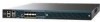
...)1 7 Management port LEDs 8 SFP distribution port Link and Activity LEDs USB ports 0 and 1 (Type A) 4 5 Console port (Mini USB Type B)1 Power supply (PS1 and PS2), System (SYS), and 9 Alarm (ALM) LEDs 10 Expansion module (EM) slot 1. Controller Overview Figure 1 Front Panel 12 345 6 Cisco 5500 Series Wireless Controller RP SP USB0 USB1 EN EN 7 12 3 4 56 7 8 Model 5508 PS1...
...)1 7 Management port LEDs 8 SFP distribution port Link and Activity LEDs USB ports 0 and 1 (Type A) 4 5 Console port (Mini USB Type B)1 Power supply (PS1 and PS2), System (SYS), and 9 Alarm (ALM) LEDs 10 Expansion module (EM) slot 1. Controller Overview Figure 1 Front Panel 12 345 6 Cisco 5500 Series Wireless Controller RP SP USB0 USB1 EN EN 7 12 3 4 56 7 8 Model 5508 PS1...

Installation Guide
Page 5
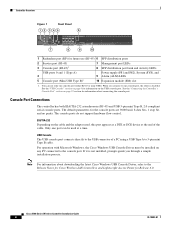
...The LED indicators are not compatible. Note An amber LED could indicate an error or a possible hardware failure. 78-18998-01 Cisco 5500 Series Wireless Controller Installation Guide 5 Conversely, when the USB cable is plugged into the USB console port the RJ-45 port becomes inactive. ... the USB port, the RJ-45 port becomes active. When a cable is removed from the console port without affecting Windows HyperTerminal operations. Figure 2 12 Back Panel 251198 3 4 1 Power supply PS1 2 Power supply PS1 on/off switch 3 Power supply PS1 AC cable connection 5 4 Power supply...
...The LED indicators are not compatible. Note An amber LED could indicate an error or a possible hardware failure. 78-18998-01 Cisco 5500 Series Wireless Controller Installation Guide 5 Conversely, when the USB cable is plugged into the USB console port the RJ-45 port becomes inactive. ... the USB port, the RJ-45 port becomes active. When a cable is removed from the console port without affecting Windows HyperTerminal operations. Figure 2 12 Back Panel 251198 3 4 1 Power supply PS1 2 Power supply PS1 on/off switch 3 Power supply PS1 AC cable connection 5 4 Power supply...
Installation Guide
Page 11
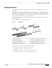
... adjustable rack-mount kit is not suitable for mounting the controller in a 2-Post Rack-Mid-Mount, page 18 78-18998-01 Cisco 5500 Series Wireless Controller Installation Guide 11 This kit is included for racks with rack... mounting brackets and the desktop or shelf mounting rubber feet in a 2-post equipment rack. Figure 3 Mounting Kit 3 2 1 5 6 78 4 251199 1 Front brackets (2) 2 Rear bracket adapters (2) 3 Short slide-mount brackets (2) 4 Long slide-mount brackets (2) 5 12...
... adjustable rack-mount kit is not suitable for mounting the controller in a 2-Post Rack-Mid-Mount, page 18 78-18998-01 Cisco 5500 Series Wireless Controller Installation Guide 11 This kit is included for racks with rack... mounting brackets and the desktop or shelf mounting rubber feet in a 2-post equipment rack. Figure 3 Mounting Kit 3 2 1 5 6 78 4 251199 1 Front brackets (2) 2 Rear bracket adapters (2) 3 Short slide-mount brackets (2) 4 Long slide-mount brackets (2) 5 12...
Installation Guide
Page 12
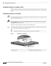
...Cisco 5500 Series Wireless Controller 12 34 56 78 Model 5508 PS1 PS2 SYS ACT 1 Front bracket 12 2 M4x0.7 x 8mm flat head screws 251200 Cisco 5500 Series Wireless Controller Installation Guide 12 78-18998-01 Unpacking and Installing the Controller Installing the Controller on a Desktop or Shelf When mounting the controller ...This unit might have more people must be removed to install the controller. Follow the same steps to attach the second bracket to mount the controller in a 4-Post Rack Caution The controller weighs 20 lbs (9.1 kg) with both power supplies installed. ...
...Cisco 5500 Series Wireless Controller 12 34 56 78 Model 5508 PS1 PS2 SYS ACT 1 Front bracket 12 2 M4x0.7 x 8mm flat head screws 251200 Cisco 5500 Series Wireless Controller Installation Guide 12 78-18998-01 Unpacking and Installing the Controller Installing the Controller on a Desktop or Shelf When mounting the controller ...This unit might have more people must be removed to install the controller. Follow the same steps to attach the second bracket to mount the controller in a 4-Post Rack Caution The controller weighs 20 lbs (9.1 kg) with both power supplies installed. ...
Installation Guide
Page 13
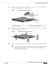
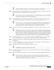
...Rear Bracket Adapters RP SP USB0 USB1 CONSOLE EN EN Cisco 5500 Series Wireless Controller 12 34 56 78 Model 5508 PS1 PS2 SYS ACT 1 2 251201 1 Rear bracket adapter 2 M3x0.5 x 6mm flat head screws Step 3 Mount the front of the controller chassis into the rack using three M3 screws (see ...depending on the rack rail thread type (see Figure 5). Figure 6 Installing the Controller in the Rack (Front) RP SP USB0 USB1 CONSOLE EN EN Cisco 5500 Series Wireless Controller 12 34 56 78 Model 5508 PS1 PS2 SYS ACT 251202 Step 4 Measure the distance between the front and rear...
...Rear Bracket Adapters RP SP USB0 USB1 CONSOLE EN EN Cisco 5500 Series Wireless Controller 12 34 56 78 Model 5508 PS1 PS2 SYS ACT 1 2 251201 1 Rear bracket adapter 2 M3x0.5 x 6mm flat head screws Step 3 Mount the front of the controller chassis into the rack using three M3 screws (see ...depending on the rack rail thread type (see Figure 5). Figure 6 Installing the Controller in the Rack (Front) RP SP USB0 USB1 CONSOLE EN EN Cisco 5500 Series Wireless Controller 12 34 56 78 Model 5508 PS1 PS2 SYS ACT 251202 Step 4 Measure the distance between the front and rear...

Installation Guide
Page 14
... Tabs Facing Front of the Controller RP SP USB0 USB1 CONSOLE EN EN Cisco 5500 Series Wireless Controller 12 34 56 78 Model 5508 PS1 PS2 SYS ACT 251203 RP SP USB0 USB1 CONSOLE EN EN Cisco 5500 Series Wireless Controller 12 34 56 78 Model 5508 PS1 PS2 SYS ACT •... the Controller RP SP USB0 USB1 CONSOLE EN EN Cisco 5500 Series Wireless Controller 12 34 56 78 Model 5508 PS1 PS2 SYS ACT RP SP USB0 USB1 CONSOLE EN EN Cisco 5500 Series Wireless Controller 12 34 56 78 Model 5508 PS1 PS2 SYS ACT 251237 Cisco 5500 Series Wireless Controller Installation Guide...
... Tabs Facing Front of the Controller RP SP USB0 USB1 CONSOLE EN EN Cisco 5500 Series Wireless Controller 12 34 56 78 Model 5508 PS1 PS2 SYS ACT 251203 RP SP USB0 USB1 CONSOLE EN EN Cisco 5500 Series Wireless Controller 12 34 56 78 Model 5508 PS1 PS2 SYS ACT •... the Controller RP SP USB0 USB1 CONSOLE EN EN Cisco 5500 Series Wireless Controller 12 34 56 78 Model 5508 PS1 PS2 SYS ACT RP SP USB0 USB1 CONSOLE EN EN Cisco 5500 Series Wireless Controller 12 34 56 78 Model 5508 PS1 PS2 SYS ACT 251237 Cisco 5500 Series Wireless Controller Installation Guide...
Installation Guide
Page 15
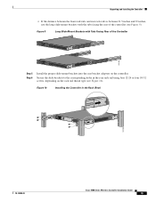
...-Mount Brackets with the tabs facing the rear of the Controller RP SP USB0 USB1 CONSOLE EN EN Cisco 5500 Series Wireless Controller 12 34 56 78 Model 5508 PS1 PS2 SYS ACT 251238 RP SP USB0 USB1 CONSOLE EN EN Cisco 5500 Series Wireless Controller 12 34 56 78 Model 5508 PS1 PS2 SYS ACT Step 5 Step 6 Install the proper...
...-Mount Brackets with the tabs facing the rear of the Controller RP SP USB0 USB1 CONSOLE EN EN Cisco 5500 Series Wireless Controller 12 34 56 78 Model 5508 PS1 PS2 SYS ACT 251238 RP SP USB0 USB1 CONSOLE EN EN Cisco 5500 Series Wireless Controller 12 34 56 78 Model 5508 PS1 PS2 SYS ACT Step 5 Step 6 Install the proper...

Installation Guide
Page 16
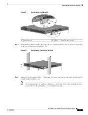
... the Cable Guide RP SP USB0 USB1 CONSOLE EN EN Cisco 5500 Series Wireless Controller 12 34 56 78 Model 5508 PS1 PS2 SYS ACT 251240 Installing the Controller in the rack. Two or more than one of the front brackets to the controller using three M4 screws (see Figure 11). Unpacking and ... obscuring the front panel of the four holes on each bracket are used (top, left or right bracket (see Figure 12). Note Only three of the switch and the other devices installed in a 2-Post Rack-Flush Mount Caution The controller weighs 20 lbs (9.1 kg) with both power supplies installed.
... the Cable Guide RP SP USB0 USB1 CONSOLE EN EN Cisco 5500 Series Wireless Controller 12 34 56 78 Model 5508 PS1 PS2 SYS ACT 251240 Installing the Controller in the rack. Two or more than one of the front brackets to the controller using three M4 screws (see Figure 11). Unpacking and ... obscuring the front panel of the four holes on each bracket are used (top, left or right bracket (see Figure 12). Note Only three of the switch and the other devices installed in a 2-Post Rack-Flush Mount Caution The controller weighs 20 lbs (9.1 kg) with both power supplies installed.
Installation Guide
Page 17
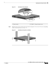
... bracket 2 M4x0.7 x 8mm flat head screws Step 2 Mount the front of the switch and the other devices installed in the Rack RP SP USB0 USB1 CONSOLE EN EN Cisco 5500 Series Wireless Controller 12 34 56 78 Model 5508 PS1 PS2 SYS ACT 274464 Step 3 (Optional) Use the supplied M4x0.7 x 20mm pan head screw to attach...
... bracket 2 M4x0.7 x 8mm flat head screws Step 2 Mount the front of the switch and the other devices installed in the Rack RP SP USB0 USB1 CONSOLE EN EN Cisco 5500 Series Wireless Controller 12 34 56 78 Model 5508 PS1 PS2 SYS ACT 274464 Step 3 (Optional) Use the supplied M4x0.7 x 20mm pan head screw to attach...

Installation Guide
Page 18
... same steps to attach the second bracket to install the controller. Unpacking and Installing the Controller Figure 14 Installing the Cable Guide RP SP USB0 USB1 CONSOLE EN EN Cisco 5500 Series Wireless Controller 12 34 56 78 Model 5508 PS1 PS2 SYS ACT 205855 Installing the Controller in a different location on each bracket are used (top, left...
... same steps to attach the second bracket to install the controller. Unpacking and Installing the Controller Figure 14 Installing the Cable Guide RP SP USB0 USB1 CONSOLE EN EN Cisco 5500 Series Wireless Controller 12 34 56 78 Model 5508 PS1 PS2 SYS ACT 205855 Installing the Controller in a different location on each bracket are used (top, left...
Installation Guide
Page 19
... the Front Brackets Unpacking and Installing the Controller RP SP USB0 USB1 CONSOLE EN EN Cisco 5500 Series Wireless Controller 12 34 56 78 Model 5508 PS1 PS2 SYS ACT 1 2 274465 1 Front bracket 2 M4x0.7 x 8mm flat head screws Step 2 Mount the front of the controller chassis into the rack using four 12-24 or four 10-32 screws...
... the Front Brackets Unpacking and Installing the Controller RP SP USB0 USB1 CONSOLE EN EN Cisco 5500 Series Wireless Controller 12 34 56 78 Model 5508 PS1 PS2 SYS ACT 1 2 274465 1 Front bracket 2 M4x0.7 x 8mm flat head screws Step 2 Mount the front of the controller chassis into the rack using four 12-24 or four 10-32 screws...

Installation Guide
Page 20
...must be the grounding type, and the grounding conductors should connect to protective earth ground at the service equipment. Unpacking and Installing the Controller Grounding the Chassis Note If you cannot use the chassis grounding pad or the provided grounding lug. A grounding pad with two threaded ...on the right side of the chassis in the wire-up position, or on the Controller (Right Side) 251241 RP SP USB0 USB1 CONSOLE EN EN Cisco 5500 Series Wireless Controller 12 34 56 78 Model 5508 PS1 PS2 SYS ACT Warning When installing or replacing the unit, the ground connection ...
...must be the grounding type, and the grounding conductors should connect to protective earth ground at the service equipment. Unpacking and Installing the Controller Grounding the Chassis Note If you cannot use the chassis grounding pad or the provided grounding lug. A grounding pad with two threaded ...on the right side of the chassis in the wire-up position, or on the Controller (Right Side) 251241 RP SP USB0 USB1 CONSOLE EN EN Cisco 5500 Series Wireless Controller 12 34 56 78 Model 5508 PS1 PS2 SYS ACT Warning When installing or replacing the unit, the ground connection ...

Installation Guide
Page 21
.... Figure 18 ESD Wrist Strap Connector Location RP SP USB0 USB1 CONSOLE EN EN Cisco 5500 Series Wireless Controller 12 34 56 78 Model 5508 PS1 PS2 SYS ACT 251239 78-18998-01 Cisco 5500 Series Wireless Controller Installation Guide 21 Unpacking and Installing the Controller Note The grounding lug must comply with National Electrical Code (NEC) for the...
.... Figure 18 ESD Wrist Strap Connector Location RP SP USB0 USB1 CONSOLE EN EN Cisco 5500 Series Wireless Controller 12 34 56 78 Model 5508 PS1 PS2 SYS ACT 251239 78-18998-01 Cisco 5500 Series Wireless Controller Installation Guide 21 Unpacking and Installing the Controller Note The grounding lug must comply with National Electrical Code (NEC) for the...
Installation Guide
Page 25
... identical. Step 11 Step 12 Step 13 Step 14 Enter the network name, or service set to optimize RRM parameter settings, such as guest web authentication and VPN termination. Enter yes to allow clients to clients, the controller's management interface, and optionally the ..., a mobility group facilitates scalable, system-wide mobility and controller redundancy while an RF group facilitates scalable, system-wide dynamic RF management. Enter the code for the group. 78-18998-01 Cisco 5500 Series Wireless Controller Installation Guide 25 Using the Startup Wizard Note The VLAN ...
... identical. Step 11 Step 12 Step 13 Step 14 Enter the network name, or service set to optimize RRM parameter settings, such as guest web authentication and VPN termination. Enter yes to allow clients to clients, the controller's management interface, and optionally the ..., a mobility group facilitates scalable, system-wide mobility and controller redundancy while an RF group facilitates scalable, system-wide dynamic RF management. Enter the code for the group. 78-18998-01 Cisco 5500 Series Wireless Controller Installation Guide 25 Using the Startup Wizard Note The VLAN ...

Data Sheet
Page 2
... without the need for a physical connection to the wired network ● Available on select Cisco Aironet access points, Enterprise Wireless Mesh is Cisco Public Information. Cisco 5500 Series Wireless LAN Controller Features Feature Scalability High Performance RF Management OfficeExtend Comprehensive End-to-End Security Enterprise Wireless Mesh High Performance Video End-to-end Voice High Availability Environmentally Responsible Mobility...
... without the need for a physical connection to the wired network ● Available on select Cisco Aironet access points, Enterprise Wireless Mesh is Cisco Public Information. Cisco 5500 Series Wireless LAN Controller Features Feature Scalability High Performance RF Management OfficeExtend Comprehensive End-to-End Security Enterprise Wireless Mesh High Performance Video End-to-end Voice High Availability Environmentally Responsible Mobility...

Data Sheet
Page 5
... 5508 Controller (eDelivery) 50 AP Adder License for the 5508 Controller (eDelivery) 100 AP Adder License for the 5508 Controller (eDelivery) 250 AP Adder License for the 5508 Controller (eDelivery) Cisco SMARTnet Service 8x5xNBD CON-SNT-LCTUPG CON-SNT-LCT25A CON-SNT-LCT50A CON-SNT-LCT100A CON-SNT-LCT250A Table 6. Ordering Information for Cisco 5500 Series Wireless Controllers Part Number AIR-CT5508-12...
... 5508 Controller (eDelivery) 50 AP Adder License for the 5508 Controller (eDelivery) 100 AP Adder License for the 5508 Controller (eDelivery) 250 AP Adder License for the 5508 Controller (eDelivery) Cisco SMARTnet Service 8x5xNBD CON-SNT-LCTUPG CON-SNT-LCT25A CON-SNT-LCT50A CON-SNT-LCT100A CON-SNT-LCT250A Table 6. Ordering Information for Cisco 5500 Series Wireless Controllers Part Number AIR-CT5508-12...

Data Sheet
Page 8
... the Cisco Unified Wireless Network framework, visit: http://www.cisco.com/go /wirelesslanservices. The Cisco 5500 Series Wireless Controller manages all the Cisco access points within campus environments and branch locations, eliminating complexity and providing network administrators with intelligent, customized services from Cisco and our partners. Service and Support Realize the full business value of your wireless network. For more about Cisco wireless controllers, contact your network...
... the Cisco Unified Wireless Network framework, visit: http://www.cisco.com/go /wirelesslanservices. The Cisco 5500 Series Wireless Controller manages all the Cisco access points within campus environments and branch locations, eliminating complexity and providing network administrators with intelligent, customized services from Cisco and our partners. Service and Support Realize the full business value of your wireless network. For more about Cisco wireless controllers, contact your network...
