
Installation Guide
Page 5
...-18998-01 Cisco 5500 Series Wireless Controller Installation Guide 5 Note Four-pin mini Type B connectors are easily confused with a power supply, a blank power supply cover, and a fan tray. Controller Overview With the Cisco Windows USB Console Driver, you can use the LED indications to quickly assess the unit's status. The LED indicators are not compatible. They...
...-18998-01 Cisco 5500 Series Wireless Controller Installation Guide 5 Note Four-pin mini Type B connectors are easily confused with a power supply, a blank power supply cover, and a fan tray. Controller Overview With the Cisco Windows USB Console Driver, you can use the LED indications to quickly assess the unit's status. The LED indicators are not compatible. They...

Installation Guide
Page 21
... 18 ESD Wrist Strap Connector Location RP SP USB0 USB1 CONSOLE EN EN Cisco 5500 Series Wireless Controller 12 34 56 78 Model 5508 PS1 PS2 SYS ACT 251239 78-18998-01 Cisco 5500 Series Wireless Controller Installation Guide 21 Always use an ESD-preventive wrist or ankle strap and ... skin contact. Ensure that it to ensure adequate earth ground. The measurement should be used and the copper conductor must be NRTL listed and compatible with copper conductors. Prepare the other equipment. To attach the grounding lug and cable to the chassis, follow these steps: Step 1 Step...
... 18 ESD Wrist Strap Connector Location RP SP USB0 USB1 CONSOLE EN EN Cisco 5500 Series Wireless Controller 12 34 56 78 Model 5508 PS1 PS2 SYS ACT 251239 78-18998-01 Cisco 5500 Series Wireless Controller Installation Guide 21 Always use an ESD-preventive wrist or ankle strap and ... skin contact. Ensure that it to ensure adequate earth ground. The measurement should be used and the copper conductor must be NRTL listed and compatible with copper conductors. Prepare the other equipment. To attach the grounding lug and cable to the chassis, follow these steps: Step 1 Step...
Installation Guide
Page 27
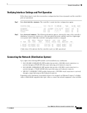
Step 1 Enter show port summary. The controller's current interface configurations appear: Step 2 Interface Name management service-port virtual Port ---LAG N/A N/A Vlan Id -------untagged N/A N/A IP Address 10.91.104.93 10.10.0.9 1.1.1.1 Type ------Static ... 5 or higher cables or SX/LX/LH compatible fiber-optic cables to connect the network equipment to which serve as the data path between the controller and Cisco lightweight access points and to the controller. 78-18998-01 Cisco 5500 Series Wireless Controller Installation Guide 27 Depending on the distribution system physical...
Step 1 Enter show port summary. The controller's current interface configurations appear: Step 2 Interface Name management service-port virtual Port ---LAG N/A N/A Vlan Id -------untagged N/A N/A IP Address 10.91.104.93 10.10.0.9 1.1.1.1 Type ------Static ... 5 or higher cables or SX/LX/LH compatible fiber-optic cables to connect the network equipment to which serve as the data path between the controller and Cisco lightweight access points and to the controller. 78-18998-01 Cisco 5500 Series Wireless Controller Installation Guide 27 Depending on the distribution system physical...