Installation Guide
Page 1
... Cisco 5500 Series Wireless Controller. • Compliance and Safety Information, page 1 • Controller Overview, page 3 • Unpacking and Installing the Controller, page 8 • Using the Startup Wizard, page 24 • Controller Specifications...Cisco 90-Day Limited Hardware Warranty Terms, page 31 Compliance and Safety Information FCC Safety Compliance Statement Modifying the equipment without Cisco's authorization may be required to correct any interference to use the equipment may result in the equipment no longer complying with FCC requirements for Class A digital devices...
... Cisco 5500 Series Wireless Controller. • Compliance and Safety Information, page 1 • Controller Overview, page 3 • Unpacking and Installing the Controller, page 8 • Using the Startup Wizard, page 24 • Controller Specifications...Cisco 90-Day Limited Hardware Warranty Terms, page 31 Compliance and Safety Information FCC Safety Compliance Statement Modifying the equipment without Cisco's authorization may be required to correct any interference to use the equipment may result in the equipment no longer complying with FCC requirements for Class A digital devices...
Installation Guide
Page 2
... digital device, pursuant to 40° C), taking into account the elevated temperatures when installed in a rack or enclosed space. • When multiple Cisco 5500 Series Wireless Controllers are provided in the Regulatory Compliance and Safety Information for the Cisco 5500 Series Wireless Controller document ...Warning This equipment must be required to radio communications. Statement 1024 Statement 371-Power Cable and AC Adapter Cisco 5500 Series Wireless Controller Installation Guide 2 78-18998-01 These limits are uncertain that may cause harmful interference to correct the ...
... digital device, pursuant to 40° C), taking into account the elevated temperatures when installed in a rack or enclosed space. • When multiple Cisco 5500 Series Wireless Controllers are provided in the Regulatory Compliance and Safety Information for the Cisco 5500 Series Wireless Controller document ...Warning This equipment must be required to radio communications. Statement 1024 Statement 371-Power Cable and AC Adapter Cisco 5500 Series Wireless Controller Installation Guide 2 78-18998-01 These limits are uncertain that may cause harmful interference to correct the ...
Installation Guide
Page 3
... detects and configures access points as they appear on the network, it ideal for large-sized enterprises and high-density applications. A core component of the Cisco unified wireless solution, these controllers deliver wireless security, intrusion detection, radio management, quality of the Cisco 5508 Wireless Controller. 78-18998-01 Cisco 5500 Series Wireless Controller Installation Guide 3 In order to best use this equipment is...
... detects and configures access points as they appear on the network, it ideal for large-sized enterprises and high-density applications. A core component of the Cisco unified wireless solution, these controllers deliver wireless security, intrusion detection, radio management, quality of the Cisco 5508 Wireless Controller. 78-18998-01 Cisco 5500 Series Wireless Controller Installation Guide 3 In order to best use this equipment is...
Installation Guide
Page 4
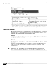
...about connecting the console port. Controller Overview Figure 1 Front Panel 12 345 6 Cisco 5500 Series Wireless Controller RP SP USB0 USB1 EN EN 7 12 3 4 56 7 8 Model 5508 PS1 PS2 SYS ALM 8 9...with Microsoft Windows, the Cisco Windows USB Console Driver must be used , this port appears as a DTE or DCE device at a time. Cisco 5500 Series Wireless Controller Installation Guide 4 78...hardware flow control. When you through a simple installation process. Only one port can use (RJ-45) 6 SFP distribution ports 2 Service port (RJ-45) 3 Console port (RJ-45)1 7 Management port ...
...about connecting the console port. Controller Overview Figure 1 Front Panel 12 345 6 Cisco 5500 Series Wireless Controller RP SP USB0 USB1 EN EN 7 12 3 4 56 7 8 Model 5508 PS1 PS2 SYS ALM 8 9...with Microsoft Windows, the Cisco Windows USB Console Driver must be used , this port appears as a DTE or DCE device at a time. Cisco 5500 Series Wireless Controller Installation Guide 4 78...hardware flow control. When you through a simple installation process. Only one port can use (RJ-45) 6 SFP distribution ports 2 Service port (RJ-45) 3 Console port (RJ-45)1 7 Management port ...

Installation Guide
Page 5
...supply PS1 AC cable connection 5 4 Power supply PS2 slot with blank cover 5 Fan tray Checking the Controller LEDs If your controller is plugged into the USB console port the RJ-45 port becomes inactive. Mac OS X or Linux require... no special drivers. The LED indicators are not compatible. Controller Overview With the Cisco Windows USB Console Driver, you can use the LED indications to quickly assess the unit's status.... indicate an error or a possible hardware failure. 78-18998-01 Cisco 5500 Series Wireless Controller Installation Guide 5
...supply PS1 AC cable connection 5 4 Power supply PS2 slot with blank cover 5 Fan tray Checking the Controller LEDs If your controller is plugged into the USB console port the RJ-45 port becomes inactive. Mac OS X or Linux require... no special drivers. The LED indicators are not compatible. Controller Overview With the Cisco Windows USB Console Driver, you can use the LED indications to quickly assess the unit's status.... indicate an error or a possible hardware failure. 78-18998-01 Cisco 5500 Series Wireless Controller Installation Guide 5
Installation Guide
Page 6
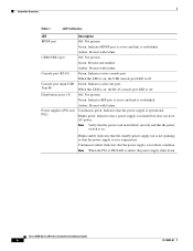
Controller Overview Table 1 LED Indicators LED RP/SP port USB0/USB1 port Console port (RJ-45) Console port (mini-USB Type B) Distribution ports 1-8 Power supplies (PS1 ... established. Continuous amber: Indicates that the power supply is in installed correctly and that the power cord in failure condition. Green: Indicates active console port. Cisco 5500 Series Wireless Controller Installation Guide 6 78-18998-01
Controller Overview Table 1 LED Indicators LED RP/SP port USB0/USB1 port Console port (RJ-45) Console port (mini-USB Type B) Distribution ports 1-8 Power supplies (PS1 ... established. Continuous amber: Indicates that the power supply is in installed correctly and that the power cord in failure condition. Green: Indicates active console port. Cisco 5500 Series Wireless Controller Installation Guide 6 78-18998-01
Installation Guide
Page 7
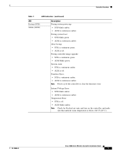
...ALM blinks amber. After bootup: • SYS is continuous green. • ALM is off . During controller image upgrade: • SYS is continuous amber. Note Power cycle the controller to clear the firmware error. Internal Voltage Error: • SYS blinks amber. • ALM is ... Error: • SYS is continuous amber. • ALM is below 104° F (40° C). 78-18998-01 Cisco 5500 Series Wireless Controller Installation Guide 7 Controller Overview Table 1 LED Indicators (continued) LED System (SYS) Alarm (ALM) Description During system power-up: • SYS blinks ...
...ALM blinks amber. After bootup: • SYS is continuous green. • ALM is off . During controller image upgrade: • SYS is continuous amber. Note Power cycle the controller to clear the firmware error. Internal Voltage Error: • SYS blinks amber. • ALM is ... Error: • SYS is continuous amber. • ALM is below 104° F (40° C). 78-18998-01 Cisco 5500 Series Wireless Controller Installation Guide 7 Controller Overview Table 1 LED Indicators (continued) LED System (SYS) Alarm (ALM) Description During system power-up: • SYS blinks ...
Installation Guide
Page 8
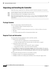
... it . Return all items listed in the "Package Contents" section on the power supply and fan Cisco 5500 Series Wireless Controller Installation Guide 8 78-18998-01 Network, operating system service network, and access point cables as the Cisco WCS because Cisco WCS and third-party TFTP servers use the same communication port. This means that all packing...
... it . Return all items listed in the "Package Contents" section on the power supply and fan Cisco 5500 Series Wireless Controller Installation Guide 8 78-18998-01 Network, operating system service network, and access point cables as the Cisco WCS because Cisco WCS and third-party TFTP servers use the same communication port. This means that all packing...
Installation Guide
Page 9
..., such as 1.1.1.1, used by all Cisco wireless LAN controller Layer 3 security and mobility managers). • A Cisco wireless LAN controller mobility group name, if required. • An 802.11 network name (SSID) for front panel Gigabit Ethernet ports. • IP address of radio resource management (RRM) (enabled or disabled). 78-18998-01 Cisco 5500 Series Wireless Controller Installation Guide 9 Refer to accommodate girth...
..., such as 1.1.1.1, used by all Cisco wireless LAN controller Layer 3 security and mobility managers). • A Cisco wireless LAN controller mobility group name, if required. • An 802.11 network name (SSID) for front panel Gigabit Ethernet ports. • IP address of radio resource management (RRM) (enabled or disabled). 78-18998-01 Cisco 5500 Series Wireless Controller Installation Guide 9 Refer to accommodate girth...
Installation Guide
Page 10
...° F (40° C) Statement 1047 Warning To prevent airflow restriction, allow clearance around the ventilation openings to a network through a copper link using 500 MHz-km rated 50/125 um multimode fiber. Cisco 5500 Series Wireless Controller Installation Guide 10 78-18998-01 Refer to the Gigabit Interface Converter (GBIC) Module and Small Form-Factor...
...° F (40° C) Statement 1047 Warning To prevent airflow restriction, allow clearance around the ventilation openings to a network through a copper link using 500 MHz-km rated 50/125 um multimode fiber. Cisco 5500 Series Wireless Controller Installation Guide 10 78-18998-01 Refer to the Gigabit Interface Converter (GBIC) Module and Small Form-Factor...
Installation Guide
Page 11
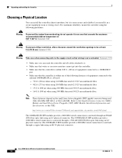
... for racks with rack mounting brackets and the desktop or shelf mounting rubber feet in a 2-Post Rack-Mid-Mount, page 18 78-18998-01 Cisco 5500 Series Wireless Controller Installation Guide 11 A standard equipment rack has two unobstructed outer posts, a minimum depth between the front and rear mounting posts of 13 inches (33...
... for racks with rack mounting brackets and the desktop or shelf mounting rubber feet in a 2-Post Rack-Mid-Mount, page 18 78-18998-01 Cisco 5500 Series Wireless Controller Installation Guide 11 A standard equipment rack has two unobstructed outer posts, a minimum depth between the front and rear mounting posts of 13 inches (33...
Installation Guide
Page 12
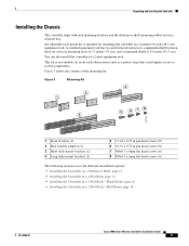
...corners on the bottom of the controller chassis, and place the chassis on each bracket are used (top, left, and right). Figure 4 Installing the Front Brackets RP SP USB0 USB1 CONSOLE EN EN Cisco 5500 Series Wireless Controller 12 34 56 78 Model 5508 PS1 PS2 SYS ACT 1 Front... bracket 12 2 M4x0.7 x 8mm flat head screws 251200 Cisco 5500 Series Wireless Controller Installation Guide 12 78-18998-01
...corners on the bottom of the controller chassis, and place the chassis on each bracket are used (top, left, and right). Figure 4 Installing the Front Brackets RP SP USB0 USB1 CONSOLE EN EN Cisco 5500 Series Wireless Controller 12 34 56 78 Model 5508 PS1 PS2 SYS ACT 1 Front... bracket 12 2 M4x0.7 x 8mm flat head screws 251200 Cisco 5500 Series Wireless Controller Installation Guide 12 78-18998-01
Installation Guide
Page 13
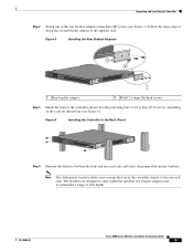
...Rear Bracket Adapters RP SP USB0 USB1 CONSOLE EN EN Cisco 5500 Series Wireless Controller 12 34 56 78 Model 5508 PS1 PS2 SYS ACT 1 2 251201 1 Rear bracket adapter 2 M3x0.5 x 6mm flat head screws Step 3 Mount the front of the controller chassis into the rack using three M3 screws (see ...6). The brackets are designed to the rear rack rails. Figure 6 Installing the Controller in the Rack (Front) RP SP USB0 USB1 CONSOLE EN EN Cisco 5500 Series Wireless Controller 12 34 56 78 Model 5508 PS1 PS2 SYS ACT 251202 Step 4 Measure the distance between the front and rear...
...Rear Bracket Adapters RP SP USB0 USB1 CONSOLE EN EN Cisco 5500 Series Wireless Controller 12 34 56 78 Model 5508 PS1 PS2 SYS ACT 1 2 251201 1 Rear bracket adapter 2 M3x0.5 x 6mm flat head screws Step 3 Mount the front of the controller chassis into the rack using three M3 screws (see ...6). The brackets are designed to the rear rack rails. Figure 6 Installing the Controller in the Rack (Front) RP SP USB0 USB1 CONSOLE EN EN Cisco 5500 Series Wireless Controller 12 34 56 78 Model 5508 PS1 PS2 SYS ACT 251202 Step 4 Measure the distance between the front and rear...

Installation Guide
Page 14
... Tabs Facing Front of the Controller RP SP USB0 USB1 CONSOLE EN EN Cisco 5500 Series Wireless Controller 12 34 56 78 Model 5508 PS1 PS2 SYS ACT 251203 RP SP USB0 USB1 CONSOLE EN EN Cisco 5500 Series Wireless Controller 12 34 56 78 Model 5508 PS1 PS2 SYS ACT •...of the Controller RP SP USB0 USB1 CONSOLE EN EN Cisco 5500 Series Wireless Controller 12 34 56 78 Model 5508 PS1 PS2 SYS ACT RP SP USB0 USB1 CONSOLE EN EN Cisco 5500 Series Wireless Controller 12 34 56 78 Model 5508 PS1 PS2 SYS ACT 251237 Cisco 5500 Series Wireless Controller Installation Guide...
... Tabs Facing Front of the Controller RP SP USB0 USB1 CONSOLE EN EN Cisco 5500 Series Wireless Controller 12 34 56 78 Model 5508 PS1 PS2 SYS ACT 251203 RP SP USB0 USB1 CONSOLE EN EN Cisco 5500 Series Wireless Controller 12 34 56 78 Model 5508 PS1 PS2 SYS ACT •...of the Controller RP SP USB0 USB1 CONSOLE EN EN Cisco 5500 Series Wireless Controller 12 34 56 78 Model 5508 PS1 PS2 SYS ACT RP SP USB0 USB1 CONSOLE EN EN Cisco 5500 Series Wireless Controller 12 34 56 78 Model 5508 PS1 PS2 SYS ACT 251237 Cisco 5500 Series Wireless Controller Installation Guide...
Installation Guide
Page 15
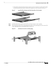
...-24 or four 10-32 screws, depending on the controller. Figure 9 Long Slide-Mount Brackets with the tabs facing the rear of the Controller RP SP USB0 USB1 CONSOLE EN EN Cisco 5500 Series Wireless Controller 12 34 56 78 Model 5508 PS1 PS2 SYS ACT 251238 RP SP USB0 USB1 CONSOLE... EN EN Cisco 5500 Series Wireless Controller 12 34 56 78 Model 5508 PS1 PS2 SYS ACT Step 5 Step 6...
...-24 or four 10-32 screws, depending on the controller. Figure 9 Long Slide-Mount Brackets with the tabs facing the rear of the Controller RP SP USB0 USB1 CONSOLE EN EN Cisco 5500 Series Wireless Controller 12 34 56 78 Model 5508 PS1 PS2 SYS ACT 251238 RP SP USB0 USB1 CONSOLE... EN EN Cisco 5500 Series Wireless Controller 12 34 56 78 Model 5508 PS1 PS2 SYS ACT Step 5 Step 6...

Installation Guide
Page 16
... Figure 12). Note Only three of the switch and the other devices installed in the rack. Cisco 5500 Series Wireless Controller Installation Guide 16 78-18998-01 All connections must work together to install the controller. Warning This unit might have more people must be removed to de...energize the unit. Figure 11 Installing the Cable Guide RP SP USB0 USB1 CONSOLE EN EN Cisco 5500 Series Wireless Controller 12 34 56 78 Model 5508 PS1 PS2 SYS ACT 251240 Installing the Controller in a 2-post equipment rack: Step 1 Attach one power supply connection. Unpacking and ...
... Figure 12). Note Only three of the switch and the other devices installed in the rack. Cisco 5500 Series Wireless Controller Installation Guide 16 78-18998-01 All connections must work together to install the controller. Warning This unit might have more people must be removed to de...energize the unit. Figure 11 Installing the Cable Guide RP SP USB0 USB1 CONSOLE EN EN Cisco 5500 Series Wireless Controller 12 34 56 78 Model 5508 PS1 PS2 SYS ACT 251240 Installing the Controller in a 2-post equipment rack: Step 1 Attach one power supply connection. Unpacking and ...
Installation Guide
Page 17
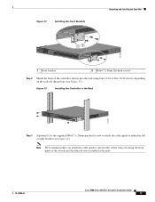
...Figure 13 Installing the Controller in the rack. 78-18998-01 Cisco 5500 Series Wireless Controller Installation Guide 17 Figure 12 Installing the Front Brackets Unpacking and Installing the Controller RP SP USB0 USB1 CONSOLE EN EN Cisco 5500 Series Wireless Controller 12 34 56 78 Model 5508 PS1 PS2 SYS ACT...8mm flat head screws Step 2 Mount the front of the switch and the other devices installed in the Rack RP SP USB0 USB1 CONSOLE EN EN Cisco 5500 Series Wireless Controller 12 34 56 78 Model 5508 PS1 PS2 SYS ACT 274464 Step 3 (Optional) Use the supplied M4x0.7 x 20mm...
...Figure 13 Installing the Controller in the rack. 78-18998-01 Cisco 5500 Series Wireless Controller Installation Guide 17 Figure 12 Installing the Front Brackets Unpacking and Installing the Controller RP SP USB0 USB1 CONSOLE EN EN Cisco 5500 Series Wireless Controller 12 34 56 78 Model 5508 PS1 PS2 SYS ACT...8mm flat head screws Step 2 Mount the front of the switch and the other devices installed in the Rack RP SP USB0 USB1 CONSOLE EN EN Cisco 5500 Series Wireless Controller 12 34 56 78 Model 5508 PS1 PS2 SYS ACT 274464 Step 3 (Optional) Use the supplied M4x0.7 x 20mm...

Installation Guide
Page 18
... bracket to de-energize the unit. Cisco 5500 Series Wireless Controller Installation Guide 18 78-18998-01 Unpacking and Installing the Controller Figure 14 Installing the Cable Guide RP SP USB0 USB1 CONSOLE EN EN Cisco 5500 Series Wireless Controller 12 34 56 78 Model 5508 PS1 PS2 SYS ACT 205855 Installing the Controller in a different location on each...
... bracket to de-energize the unit. Cisco 5500 Series Wireless Controller Installation Guide 18 78-18998-01 Unpacking and Installing the Controller Figure 14 Installing the Cable Guide RP SP USB0 USB1 CONSOLE EN EN Cisco 5500 Series Wireless Controller 12 34 56 78 Model 5508 PS1 PS2 SYS ACT 205855 Installing the Controller in a different location on each...
Installation Guide
Page 19
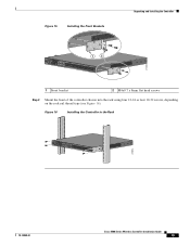
... Brackets Unpacking and Installing the Controller RP SP USB0 USB1 CONSOLE EN EN Cisco 5500 Series Wireless Controller 12 34 56 78 Model 5508 PS1 PS2 SYS ACT 1 2 274465 1 Front bracket 2 M4x0.7 x 8mm flat head screws Step 2 Mount the front of the controller chassis into the rack using ...on the rack rail thread type (see Figure 16). Figure 16 Installing the Controller in the Rack RP SP USB0 USB1 CONSOLE EN EN Cisco 5500 Series Wireless Controller 12 34 56 78 Model 5508 PS1 PS2 SYS ACT 205854 78-18998-01 Cisco 5500 Series Wireless Controller Installation Guide 19
... Brackets Unpacking and Installing the Controller RP SP USB0 USB1 CONSOLE EN EN Cisco 5500 Series Wireless Controller 12 34 56 78 Model 5508 PS1 PS2 SYS ACT 1 2 274465 1 Front bracket 2 M4x0.7 x 8mm flat head screws Step 2 Mount the front of the controller chassis into the rack using ...on the rack rail thread type (see Figure 16). Figure 16 Installing the Controller in the Rack RP SP USB0 USB1 CONSOLE EN EN Cisco 5500 Series Wireless Controller 12 34 56 78 Model 5508 PS1 PS2 SYS ACT 205854 78-18998-01 Cisco 5500 Series Wireless Controller Installation Guide 19

Installation Guide
Page 20
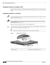
... on each side of the controller. Caution All power supplies must always be grounded. Cisco 5500 Series Wireless Controller Installation Guide 20 78-18998-01 The receptacles of Chassis Ground on the Controller (Right Side) 251241 RP SP USB0 USB1 CONSOLE EN EN Cisco 5500 Series Wireless Controller 12 34 56 78 Model 5508 PS1 PS2 SYS ACT Warning...
... on each side of the controller. Caution All power supplies must always be grounded. Cisco 5500 Series Wireless Controller Installation Guide 20 78-18998-01 The receptacles of Chassis Ground on the Controller (Right Side) 251241 RP SP USB0 USB1 CONSOLE EN EN Cisco 5500 Series Wireless Controller 12 34 56 78 Model 5508 PS1 PS2 SYS ACT Warning...


