Installation Guide
Page 2
...in the translated safety warnings that accompanied this device. You are general warnings that may cause harmful interference to correct the interference at the end of the electrical ground before installing the controller. Operation of this guide in procedures that apply...equipment in the Regulatory Compliance and Safety Information for the Cisco 5500 Series Wireless Controller document that could cause bodily injury. Contact the appropriate electrical inspection authority or an electrician if you are mounted in an equipment rack, be familiar with the instruction ...
...in the translated safety warnings that accompanied this device. You are general warnings that may cause harmful interference to correct the interference at the end of the electrical ground before installing the controller. Operation of this guide in procedures that apply...equipment in the Regulatory Compliance and Safety Information for the Cisco 5500 Series Wireless Controller document that could cause bodily injury. Contact the appropriate electrical inspection authority or an electrician if you are mounted in an equipment rack, be familiar with the instruction ...
Installation Guide
Page 8
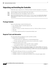
...contains the following items: • Cisco 5500 Series Wireless Controller and power cord • Mounting hardware kit • Regulatory Compliance and Safety Information for the Cisco 5500 Series Wireless Controller • This guide • Cisco product registration and Cisco documentation feedback cards Required Tools and...cannot run on CLI console (PC, laptop, or palmtop) - Network, operating system service network, and access point cables as the Cisco WCS because Cisco WCS and third-party TFTP servers use the same communication port. Cisco uses an integral TFTP server.
...contains the following items: • Cisco 5500 Series Wireless Controller and power cord • Mounting hardware kit • Regulatory Compliance and Safety Information for the Cisco 5500 Series Wireless Controller • This guide • Cisco product registration and Cisco documentation feedback cards Required Tools and...cannot run on CLI console (PC, laptop, or palmtop) - Network, operating system service network, and access point cables as the Cisco WCS because Cisco WCS and third-party TFTP servers use the same communication port. Cisco uses an integral TFTP server.
Installation Guide
Page 10
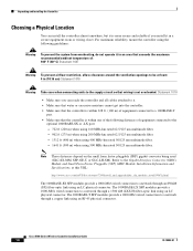
...GLC-LH-SM). The 1000BASE-T SFP modules provide a 1000-Mb/s wired connection to a network through a 1300 nM (LX/LH) fiber-optic link using an LC physical connector. For maximum reliability, mount the controller using the following distances of equipment connected to the optional 1000BASE-SX or -LX port: -...1641 ft (500 m) when using 500 MHz-km rated 50/125 um multimode fiber. Cisco 5500 Series Wireless Controller Installation Guide 10 78-18998-01 Statement 1018 • Make sure you can install the controller almost anywhere, but it is more secure and reliable if you install it in a ...
...GLC-LH-SM). The 1000BASE-T SFP modules provide a 1000-Mb/s wired connection to a network through a 1300 nM (LX/LH) fiber-optic link using an LC physical connector. For maximum reliability, mount the controller using the following distances of equipment connected to the optional 1000BASE-SX or -LX port: -...1641 ft (500 m) when using 500 MHz-km rated 50/125 um multimode fiber. Cisco 5500 Series Wireless Controller Installation Guide 10 78-18998-01 Statement 1018 • Make sure you can install the controller almost anywhere, but it is more secure and reliable if you install it in a ...
Installation Guide
Page 11
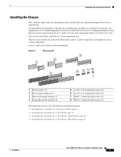
You can also install the controller in a 2-Post Rack-Mid-Mount, page 18 78-18998-01 Cisco 5500 Series Wireless Controller Installation Guide 11 Figure 3 Mounting Kit 3 2 1 5 6 78 4 251199 1 Front brackets (2) 2 Rear bracket adapters (2) 3 Short slide-mount brackets (2) 4 Long slide-mount brackets (2) 5 12-24 x 0.75 in pan head screws (8) 6 10-32 x 0.75 in pan head screws (8) 7 M4x0.7 x 8mm flat...
You can also install the controller in a 2-Post Rack-Mid-Mount, page 18 78-18998-01 Cisco 5500 Series Wireless Controller Installation Guide 11 Figure 3 Mounting Kit 3 2 1 5 6 78 4 251199 1 Front brackets (2) 2 Rear bracket adapters (2) 3 Short slide-mount brackets (2) 4 Long slide-mount brackets (2) 5 12-24 x 0.75 in pan head screws (8) 6 10-32 x 0.75 in pan head screws (8) 7 M4x0.7 x 8mm flat...
Installation Guide
Page 12
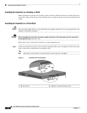
... horizontal surface. All connections must work together to mount the controller in a 4-Post Rack Caution The controller weighs 20 lbs (9.1 kg) with both power supplies installed. Figure 4 Installing the Front Brackets RP SP USB0 USB1 CONSOLE EN EN Cisco 5500 Series Wireless Controller 12 34 56 78 Model 5508 PS1 PS2 SYS ACT 1 Front bracket 12 2 M4x0...
... horizontal surface. All connections must work together to mount the controller in a 4-Post Rack Caution The controller weighs 20 lbs (9.1 kg) with both power supplies installed. Figure 4 Installing the Front Brackets RP SP USB0 USB1 CONSOLE EN EN Cisco 5500 Series Wireless Controller 12 34 56 78 Model 5508 PS1 PS2 SYS ACT 1 Front bracket 12 2 M4x0...
Installation Guide
Page 13
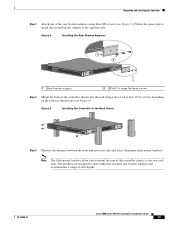
... Rear Bracket Adapters RP SP USB0 USB1 CONSOLE EN EN Cisco 5500 Series Wireless Controller 12 34 56 78 Model 5508 PS1 PS2 SYS ACT 1 2 251201 1 Rear bracket adapter 2 M3x0.5 x 6mm flat head screws Step 3 Mount the front of rack depths. 78-18998-01 Cisco 5500 Series Wireless Controller Installation Guide 13 The brackets are designed to slide...
... Rear Bracket Adapters RP SP USB0 USB1 CONSOLE EN EN Cisco 5500 Series Wireless Controller 12 34 56 78 Model 5508 PS1 PS2 SYS ACT 1 2 251201 1 Rear bracket adapter 2 M3x0.5 x 6mm flat head screws Step 3 Mount the front of rack depths. 78-18998-01 Cisco 5500 Series Wireless Controller Installation Guide 13 The brackets are designed to slide...

Installation Guide
Page 14
... CONSOLE EN EN Cisco 5500 Series Wireless Controller 12 34 56 78 Model 5508 PS1 PS2 SYS ACT 251237 Cisco 5500 Series Wireless Controller Installation Guide 14 78-18998-01 Figure 7 Short Slide-Mount Brackets with Tabs Facing Front of the Controller RP SP USB0 USB1 CONSOLE EN EN Cisco 5500 Series Wireless Controller 12 34 56 78 Model 5508 PS1 PS2 SYS...
... CONSOLE EN EN Cisco 5500 Series Wireless Controller 12 34 56 78 Model 5508 PS1 PS2 SYS ACT 251237 Cisco 5500 Series Wireless Controller Installation Guide 14 78-18998-01 Figure 7 Short Slide-Mount Brackets with Tabs Facing Front of the Controller RP SP USB0 USB1 CONSOLE EN EN Cisco 5500 Series Wireless Controller 12 34 56 78 Model 5508 PS1 PS2 SYS...
Installation Guide
Page 15
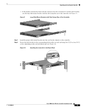
... holes in the Rack (Rear) 251204 78-18998-01 Cisco 5500 Series Wireless Controller Installation Guide 15 Figure 9 Long Slide-Mount Brackets with the tabs facing the rear of the Controller RP SP USB0 USB1 CONSOLE EN EN Cisco 5500 Series Wireless Controller 12 34 56 78 Model 5508 PS1 PS2 SYS ACT 251238 RP SP USB0 USB1 CONSOLE...
... holes in the Rack (Rear) 251204 78-18998-01 Cisco 5500 Series Wireless Controller Installation Guide 15 Figure 9 Long Slide-Mount Brackets with the tabs facing the rear of the Controller RP SP USB0 USB1 CONSOLE EN EN Cisco 5500 Series Wireless Controller 12 34 56 78 Model 5508 PS1 PS2 SYS ACT 251238 RP SP USB0 USB1 CONSOLE...

Installation Guide
Page 16
... other devices installed in the rack. Figure 11 Installing the Cable Guide RP SP USB0 USB1 CONSOLE EN EN Cisco 5500 Series Wireless Controller 12 34 56 78 Model 5508 PS1 PS2 SYS ACT 251240 Installing the Controller in a 2-post equipment rack: Step 1 Attach one power supply connection. Statement 1028 Follow these steps to flush mount the controller...
... other devices installed in the rack. Figure 11 Installing the Cable Guide RP SP USB0 USB1 CONSOLE EN EN Cisco 5500 Series Wireless Controller 12 34 56 78 Model 5508 PS1 PS2 SYS ACT 251240 Installing the Controller in a 2-post equipment rack: Step 1 Attach one power supply connection. Statement 1028 Follow these steps to flush mount the controller...
Installation Guide
Page 17
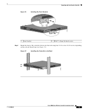
... SYS ACT 12 251200 1 Front bracket 2 M4x0.7 x 8mm flat head screws Step 2 Mount the front of the switch and the other devices installed in the Rack RP SP USB0 USB1 CONSOLE EN EN Cisco 5500 Series Wireless Controller 12 34 56 78 Model 5508 PS1 PS2 SYS ACT 274464 Step 3 (Optional) Use the supplied M4x0.7 x 20mm...
... SYS ACT 12 251200 1 Front bracket 2 M4x0.7 x 8mm flat head screws Step 2 Mount the front of the switch and the other devices installed in the Rack RP SP USB0 USB1 CONSOLE EN EN Cisco 5500 Series Wireless Controller 12 34 56 78 Model 5508 PS1 PS2 SYS ACT 274464 Step 3 (Optional) Use the supplied M4x0.7 x 20mm...

Installation Guide
Page 18
... attach the second bracket to mount the controller in a 2-Post Rack-Mid-Mount Caution The controller weighs 20 lbs (9.1 kg) with both power supplies installed. Unpacking and Installing the Controller Figure 14 Installing the Cable Guide RP SP USB0 USB1 CONSOLE EN EN Cisco 5500 Series Wireless Controller 12 34 56 78 Model 5508 PS1 PS2 SYS ACT 205855...
... attach the second bracket to mount the controller in a 2-Post Rack-Mid-Mount Caution The controller weighs 20 lbs (9.1 kg) with both power supplies installed. Unpacking and Installing the Controller Figure 14 Installing the Cable Guide RP SP USB0 USB1 CONSOLE EN EN Cisco 5500 Series Wireless Controller 12 34 56 78 Model 5508 PS1 PS2 SYS ACT 205855...
Installation Guide
Page 19
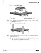
Figure 15 Installing the Front Brackets Unpacking and Installing the Controller RP SP USB0 USB1 CONSOLE EN EN Cisco 5500 Series Wireless Controller 12 34 56 78 Model 5508 PS1 PS2 SYS ACT 1 2 274465 1 Front bracket 2 M4x0.7 x 8mm flat head screws Step 2 Mount the front of the controller chassis into the rack using four 12-24 or four...
Figure 15 Installing the Front Brackets Unpacking and Installing the Controller RP SP USB0 USB1 CONSOLE EN EN Cisco 5500 Series Wireless Controller 12 34 56 78 Model 5508 PS1 PS2 SYS ACT 1 2 274465 1 Front bracket 2 M4x0.7 x 8mm flat head screws Step 2 Mount the front of the controller chassis into the rack using four 12-24 or four...

Installation Guide
Page 20
... need to protective earth ground at the service equipment. Unpacking and Installing the Controller Grounding the Chassis Note If you mid-mounted the chassis in a different location on the chassis (such as the rear bracket mount holes using an M3 screw) using your own grounding lug. Note To maintain... the wire-up position, or on the right side of Chassis Ground on the Controller (Right Side) 251241 RP SP USB0 USB1 CONSOLE EN EN Cisco 5500 Series Wireless Controller 12 34 56 78 Model 5508 PS1 PS2 SYS ACT Warning When installing or replacing the unit, the ground connection ...
... need to protective earth ground at the service equipment. Unpacking and Installing the Controller Grounding the Chassis Note If you mid-mounted the chassis in a different location on the chassis (such as the rear bracket mount holes using an M3 screw) using your own grounding lug. Note To maintain... the wire-up position, or on the right side of Chassis Ground on the Controller (Right Side) 251241 RP SP USB0 USB1 CONSOLE EN EN Cisco 5500 Series Wireless Controller 12 34 56 78 Model 5508 PS1 PS2 SYS ACT Warning When installing or replacing the unit, the ground connection ...

Data Sheet
Page 5
...-5500= AIR-CT5500-RK-MNT Product Name 5500 Series Wireless Controller Redundant AC Power Supply 5500 Series Wireless Controller Fan Tray 5500 Series Wireless Controller Spare mounting kit Additive Capacity Upgrade Licenses Tables 5 and 6 list additive capacity upgrade licenses for Cisco 5500 Series Wireless Controllers. Paper License Ordering Information for the 5508 Controller Cisco SMARTnet Service 8x5xNBD CON-SNT-LCTUPG CON-SNT-LCT25A...
...-5500= AIR-CT5500-RK-MNT Product Name 5500 Series Wireless Controller Redundant AC Power Supply 5500 Series Wireless Controller Fan Tray 5500 Series Wireless Controller Spare mounting kit Additive Capacity Upgrade Licenses Tables 5 and 6 list additive capacity upgrade licenses for Cisco 5500 Series Wireless Controllers. Paper License Ordering Information for the 5508 Controller Cisco SMARTnet Service 8x5xNBD CON-SNT-LCTUPG CON-SNT-LCT25A...
