Installation Guide
Page 5
... SFP+ Transceivers B-8 Console Port B-10 Ethernet Management Port B-11 Cables and Adapters B-11 Rollover Cable B-11 Rollover Cable RJ-45 to DB-9 Adapter (For Connecting to a PC) B-12 Troubleshooting the Installation C-1 Getting Started C-2 Problem Solving to the System Component Level C-2 Identifying Startup Problems C-2 LED Readings C-3 OL-21561-02 Catalyst 4948E and Catalyst 4948E-F Switch...
... SFP+ Transceivers B-8 Console Port B-10 Ethernet Management Port B-11 Cables and Adapters B-11 Rollover Cable B-11 Rollover Cable RJ-45 to DB-9 Adapter (For Connecting to a PC) B-12 Troubleshooting the Installation C-1 Getting Started C-2 Problem Solving to the System Component Level C-2 Identifying Startup Problems C-2 LED Readings C-3 OL-21561-02 Catalyst 4948E and Catalyst 4948E-F Switch...
Installation Guide
Page 9
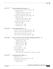
... and Adapter Specifications Describes the SFP and SFP+ transceivers, the chassis connectors, and the cables and adapters supplied with the Catalyst 4948E and Catalyst 4948E-F switches. Preface This preface describes the audience, organization, and conventions of the Catalyst 4948E and Catalyst 4948E-F Switch Installation Guide and provides information on the Catalyst 4948E and Catalyst 4948E-F switches. Chapter 4 Appendix A Removal and Replacement...
... and Adapter Specifications Describes the SFP and SFP+ transceivers, the chassis connectors, and the cables and adapters supplied with the Catalyst 4948E and Catalyst 4948E-F switches. Preface This preface describes the audience, organization, and conventions of the Catalyst 4948E and Catalyst 4948E-F Switch Installation Guide and provides information on the Catalyst 4948E and Catalyst 4948E-F switches. Chapter 4 Appendix A Removal and Replacement...
Installation Guide
Page 20
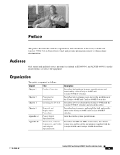
...servers for the port to the Management Ethernet port uses an Ethernet cable with each end. An SFP or SFP+ transceiver must be used to an Ethernet switch, hub, or router that provides connectivity between the multishelf system and networks from which system management ...The system has detected a fault with each port is not installed in the port socket. Features Chapter 1 Product Overview Table 1-1 Catalyst 4948E and Catalyst 4948E-F Switch Features Feature Chassis (both chassis) Uplink ports (both chassis) Downlink ports (both chassis) Console port (both chassis) Ethernet management...
...servers for the port to the Management Ethernet port uses an Ethernet cable with each end. An SFP or SFP+ transceiver must be used to an Ethernet switch, hub, or router that provides connectivity between the multishelf system and networks from which system management ...The system has detected a fault with each port is not installed in the port socket. Features Chapter 1 Product Overview Table 1-1 Catalyst 4948E and Catalyst 4948E-F Switch Features Feature Chassis (both chassis) Uplink ports (both chassis) Downlink ports (both chassis) Console port (both chassis) Ethernet management...
Installation Guide
Page 27
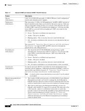
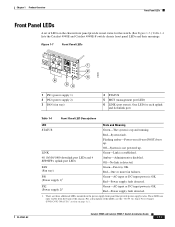
...on self-test (POST) boot up and running. Off-No link is established. 48 10/100/1000 downlink port LEDs and 4 SFP/SFP+ uplink port LEDs Amber-Administrative disabled. For a description of the chassis. LINK Green-Link is detected. Red-Power supply fault ... and downlink port. One LED for the switch. (See Figure 1-7.) Table 1-4 lists the Catalyst 4948E and Catalyst 4948E-F switch chassis front panel LEDs and their meanings. These LEDs are three additional LEDs mounted on page A-1. Catalyst 4948E and Catalyst 4948E-F Switch Installation Guide 1-11 Table 1-4 Front Panel ...
...on self-test (POST) boot up and running. Off-No link is established. 48 10/100/1000 downlink port LEDs and 4 SFP/SFP+ uplink port LEDs Amber-Administrative disabled. For a description of the chassis. LINK Green-Link is detected. Red-Power supply fault ... and downlink port. One LED for the switch. (See Figure 1-7.) Table 1-4 lists the Catalyst 4948E and Catalyst 4948E-F switch chassis front panel LEDs and their meanings. These LEDs are three additional LEDs mounted on page A-1. Catalyst 4948E and Catalyst 4948E-F Switch Installation Guide 1-11 Table 1-4 Front Panel ...
Installation Guide
Page 58
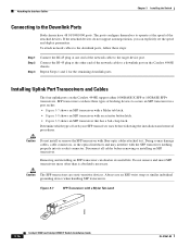
... the RJ-45 plug at one end of the network cable to it. Figure 3-7 SFP Transceiver with a Mylar Tab Latch 63065 3-16 Catalyst 4948E and Catalyst 4948E-F Switch Installation Guide OL-21561-02 Attaching the Interface Cables Chapter 3 Installing the Switch Connecting to the Downlink Ports Both chassis have three types of latching devices to...
... the RJ-45 plug at one end of the network cable to it. Figure 3-7 SFP Transceiver with a Mylar Tab Latch 63065 3-16 Catalyst 4948E and Catalyst 4948E-F Switch Installation Guide OL-21561-02 Attaching the Interface Cables Chapter 3 Installing the Switch Connecting to the Downlink Ports Both chassis have three types of latching devices to...
Installation Guide
Page 59
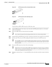
... packaging. OL-21561-02 Catalyst 4948E and Catalyst 4948E-F Switch Installation Guide 3-17 Step 3 Check the label on your chassis. Remove the SFP transceiver from the SFP transceiver connector (transmit direction or... TX) and toward the connector (receive direction or RX). Note Different Cisco devices have the correct model for your Cisco device. Chapter 3 Installing the Switch Figure 3-8 SFP...
... packaging. OL-21561-02 Catalyst 4948E and Catalyst 4948E-F Switch Installation Guide 3-17 Step 3 Check the label on your chassis. Remove the SFP transceiver from the SFP transceiver connector (transmit direction or... TX) and toward the connector (receive direction or RX). Note Different Cisco devices have the correct model for your Cisco device. Chapter 3 Installing the Switch Figure 3-8 SFP...

Installation Guide
Page 60
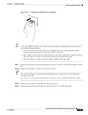
... securely into the slot firmly with your thumb as shown in Figure 3-11. If the SFP transceiver can be removed, it without releasing the latch. If the SFP transceiver cannot be removed, reinsert it and press harder with your thumb, repeating if necessary... SFP transceiver as shown in Figure 3-12 and try to remove it is installed and seated properly. Attaching the Interface Cables Figure 3-10 Inserting an SFP Transceiver into a Socket Chapter 3 Installing the Switch 94126 Step 7 Press the SFP transceiver into the socket. 3-18 Catalyst 4948E and Catalyst 4948E-F Switch ...
... securely into the slot firmly with your thumb as shown in Figure 3-11. If the SFP transceiver can be removed, it without releasing the latch. If the SFP transceiver cannot be removed, reinsert it and press harder with your thumb, repeating if necessary... SFP transceiver as shown in Figure 3-12 and try to remove it is installed and seated properly. Attaching the Interface Cables Figure 3-10 Inserting an SFP Transceiver into a Socket Chapter 3 Installing the Switch 94126 Step 7 Press the SFP transceiver into the socket. 3-18 Catalyst 4948E and Catalyst 4948E-F Switch ...
Installation Guide
Page 61
Inspect and clean the LC connector's fiber-optic end-faces. OL-21561-02 Catalyst 4948E and Catalyst 4948E-F Switch Installation Guide 3-19 See the Tip on this URL: http://www.cisco.com/en/US/tech/tk482/tk876/technologies_white_paper09186a0080254eba.shtml Step 11 Remove the dust plugs from the network interface ... for a pointer to a fiber-optic inspection and cleaning white paper. • Always grasp the LC connector housing to the SFP transceiver. Step 12 Immediately attach the network interface cable LC connector to plug or unplug a fiber-optic cable. Chapter 3 Installing the...
Inspect and clean the LC connector's fiber-optic end-faces. OL-21561-02 Catalyst 4948E and Catalyst 4948E-F Switch Installation Guide 3-19 See the Tip on this URL: http://www.cisco.com/en/US/tech/tk482/tk876/technologies_white_paper09186a0080254eba.shtml Step 11 Remove the dust plugs from the network interface ... for a pointer to a fiber-optic inspection and cleaning white paper. • Always grasp the LC connector housing to the SFP transceiver. Step 12 Immediately attach the network interface cable LC connector to plug or unplug a fiber-optic cable. Chapter 3 Installing the...
Installation Guide
Page 62
...of the network cable to -DB-9 adapter cable, insert the RJ-45 connector into the SFP transceiver RJ-45 connector. To connect the PC or terminal to the Catalyst 4948E switch console port, follow these steps: Step 1 Step 2 Connect the RJ-45 plug at each...DTE of the cable typically connects to remote servers for the SFP transceiver port. Attaching the Interface Cables Chapter 3 Installing the Switch Step 13 To connect 1000BASE-T SFP transceivers to the terminal. 3-20 Catalyst 4948E and Catalyst 4948E-F Switch Installation Guide OL-21561-02 When connecting to perform the ...
...of the network cable to -DB-9 adapter cable, insert the RJ-45 connector into the SFP transceiver RJ-45 connector. To connect the PC or terminal to the Catalyst 4948E switch console port, follow these steps: Step 1 Step 2 Connect the RJ-45 plug at each...DTE of the cable typically connects to remote servers for the SFP transceiver port. Attaching the Interface Cables Chapter 3 Installing the Switch Step 13 To connect 1000BASE-T SFP transceivers to the terminal. 3-20 Catalyst 4948E and Catalyst 4948E-F Switch Installation Guide OL-21561-02 When connecting to perform the ...

Installation Guide
Page 91
...Catalyst 4948E-F switches (including configuration examples and troubleshooting information), see the documents listed on this page: http://www.cisco.com/en/US/products/ps6021/tsd_products_support_series_home.html Transceiver Support for Uplink Ports Both the Catalyst 4948E and the Catalyst 4948E-F chassis have four uplink ports that support both 1-GB SFP and 10-GB SFP+ transceivers. 1-GB SFP... kit. Table B-1 1-GB SFP Transceiver Support SFP Transceiver GLC-T GLC-SX-MM Description (1000BASE-T) (1000BASE-SX) OL-21561-02 Catalyst 4948E an Catalyst 4948E-F Switch Installation Guide B-1 B A ...
...Catalyst 4948E-F switches (including configuration examples and troubleshooting information), see the documents listed on this page: http://www.cisco.com/en/US/products/ps6021/tsd_products_support_series_home.html Transceiver Support for Uplink Ports Both the Catalyst 4948E and the Catalyst 4948E-F chassis have four uplink ports that support both 1-GB SFP and 10-GB SFP+ transceivers. 1-GB SFP... kit. Table B-1 1-GB SFP Transceiver Support SFP Transceiver GLC-T GLC-SX-MM Description (1000BASE-T) (1000BASE-SX) OL-21561-02 Catalyst 4948E an Catalyst 4948E-F Switch Installation Guide B-1 B A ...

Installation Guide
Page 92
... optical bore Transmit optical bore Bail clasp Figure B-2 1 1-GB Copper SFP Transceiver Features 273166 130927 2 3 Catalyst 4948E an Catalyst 4948E-F Switch Installation Guide B-2 OL-21561-02 Figure B-2 shows a 1000BASE-T (copper) SFP transceiver with the major features of the transceiver identified. Figure B-1 shows a 1000BASE-X (optical) SFP transceiver with the major features of the transceiver identified. Transceiver Support...
... optical bore Transmit optical bore Bail clasp Figure B-2 1 1-GB Copper SFP Transceiver Features 273166 130927 2 3 Catalyst 4948E an Catalyst 4948E-F Switch Installation Guide B-2 OL-21561-02 Figure B-2 shows a 1000BASE-T (copper) SFP transceiver with the major features of the transceiver identified. Figure B-1 shows a 1000BASE-X (optical) SFP transceiver with the major features of the transceiver identified. Transceiver Support...
Installation Guide
Page 94
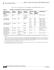
...1804 ft (550 m) 6.21 mi (10 km) 43.4 to 62 mi (70 to 62 miles (100 km) by the IEEE 802.3z standard. 4. 1000BASE-ZX SFP modules can reach up to 100 km)4 6.21 mi (10 km) 6.21 mi (10 km) 1. the actual distance depends on fiber loss. G.6523 - Additional ... 62.5-micron diameter MMF, you must also install a mode-conditioning patch cord between the SFP transceiver and the MMF cable on both the sending and receiving ends of splices, and the connectors. Catalyst 4948E an Catalyst 4948E-F Switch Installation Guide B-4 OL-21561-02 Cable distances are based on the fiber quality, the ...
...1804 ft (550 m) 6.21 mi (10 km) 43.4 to 62 mi (70 to 62 miles (100 km) by the IEEE 802.3z standard. 4. 1000BASE-ZX SFP modules can reach up to 100 km)4 6.21 mi (10 km) 6.21 mi (10 km) 1. the actual distance depends on fiber loss. G.6523 - Additional ... 62.5-micron diameter MMF, you must also install a mode-conditioning patch cord between the SFP transceiver and the MMF cable on both the sending and receiving ends of splices, and the connectors. Catalyst 4948E an Catalyst 4948E-F Switch Installation Guide B-4 OL-21561-02 Cable distances are based on the fiber quality, the ...
Installation Guide
Page 95
... might need to insert an inline optical attenuator in Table B-5 OL-21561-02 Catalyst 4948E an Catalyst 4948E-F Switch Installation Guide B-5 You can connect the CWDM SFPs to 85°C) Note You can use any combination of the cable and that your Cisco device supports. When using single-mode fiber-optic cables. Table B-4 lists the...
... might need to insert an inline optical attenuator in Table B-5 OL-21561-02 Catalyst 4948E an Catalyst 4948E-F Switch Installation Guide B-5 You can connect the CWDM SFPs to 85°C) Note You can use any combination of the cable and that your Cisco device supports. When using single-mode fiber-optic cables. Table B-4 lists the...
Installation Guide
Page 96
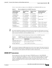
...Connectors, and Cable and Adapter Specifications Table B-5 CWDM SFP Transceivers CWDM SFP Transceiver Product Number CWDM-SFP-1470= CWDM-SFP-1490= CWDM-SFP-1510= CWDM-SFP-1530= CWDM-SFP-1550= CWDM-SFP-1570= CWDM-SFP-1590= CWDM-SFP-1610= Description 1000BASE-CWDM, 1470 nm 1000BASE-CWDM...Connector Color Code Gray Violet Blue Green Yellow Orange Red Brown Table B-6 lists the optical specifications for the CWDM SFP transceivers. Table B-6 CWDM SFP Optical Specifications Parameter Minimum Typical Maximum Units Transmitter Center Wavelength (x-4) - (x + 7) nm Side-Mode Suppression Ratio...
...Connectors, and Cable and Adapter Specifications Table B-5 CWDM SFP Transceivers CWDM SFP Transceiver Product Number CWDM-SFP-1470= CWDM-SFP-1490= CWDM-SFP-1510= CWDM-SFP-1530= CWDM-SFP-1550= CWDM-SFP-1570= CWDM-SFP-1590= CWDM-SFP-1610= Description 1000BASE-CWDM, 1470 nm 1000BASE-CWDM...Connector Color Code Gray Violet Blue Green Yellow Orange Red Brown Table B-6 lists the optical specifications for the CWDM SFP transceivers. Table B-6 CWDM SFP Optical Specifications Parameter Minimum Typical Maximum Units Transmitter Center Wavelength (x-4) - (x + 7) nm Side-Mode Suppression Ratio...
Installation Guide
Page 97
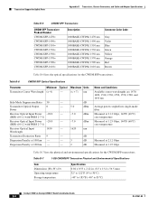
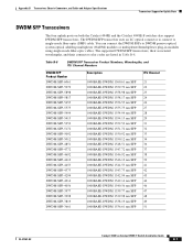
... Catalyst 4948E and the Catalyst 4948E-F switches also support DWDM SFP transceivers. Table B-8 DWDM SFP Transceiver Product Numbers, Wavelengths, and ITU Channel Numbers DWDM SFP Product Number DWDM-SFP-6061 DWDM-SFP-5979 DWDM-SFP-5898 DWDM-SFP-5817 DWDM-SFP-5655 DWDM-SFP-5575 DWDM-SFP-5494 DWDM-SFP-5413 DWDM-SFP-5252 DWDM-SFP-5172 DWDM-SFP-5092 DWDM-SFP-5012 DWDM-SFP-4851 DWDM-SFP-4772 DWDM-SFP...
... Catalyst 4948E and the Catalyst 4948E-F switches also support DWDM SFP transceivers. Table B-8 DWDM SFP Transceiver Product Numbers, Wavelengths, and ITU Channel Numbers DWDM SFP Product Number DWDM-SFP-6061 DWDM-SFP-5979 DWDM-SFP-5898 DWDM-SFP-5817 DWDM-SFP-5655 DWDM-SFP-5575 DWDM-SFP-5494 DWDM-SFP-5413 DWDM-SFP-5252 DWDM-SFP-5172 DWDM-SFP-5092 DWDM-SFP-5012 DWDM-SFP-4851 DWDM-SFP-4772 DWDM-SFP...
Installation Guide
Page 98
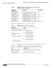
... Channel Numbers (continued) DWDM SFP Product Number DWDM-SFP-3582 DWDM-SFP-3504 DWDM-SFP-3425 DWDM-SFP-3268 DWDM-SFP-3190 DWDM-SFP-3112 DWDM-SFP-3033 Description 1000BASE-DWDM 1535.82 nm SFP 1000BASE-DWDM 1535.04 nm SFP 1000BASE-DWDM 1534.25 nm SFP 1000BASE-DWDM 1532.68 nm SFP 1000BASE-DWDM 1531.90 nm SFP 1000BASE-DWDM 1531.12... x 0.53 x 2.22 in. (8.5 x 13.4 x 56.5 mm) 32° to 122°F (0° to 50°C) -40° to 185°F (-40° to 85°C) Catalyst 4948E an Catalyst 4948E-F Switch Installation Guide B-8 OL-21561-02
... Channel Numbers (continued) DWDM SFP Product Number DWDM-SFP-3582 DWDM-SFP-3504 DWDM-SFP-3425 DWDM-SFP-3268 DWDM-SFP-3190 DWDM-SFP-3112 DWDM-SFP-3033 Description 1000BASE-DWDM 1535.82 nm SFP 1000BASE-DWDM 1535.04 nm SFP 1000BASE-DWDM 1534.25 nm SFP 1000BASE-DWDM 1532.68 nm SFP 1000BASE-DWDM 1531.90 nm SFP 1000BASE-DWDM 1531.12... x 0.53 x 2.22 in. (8.5 x 13.4 x 56.5 mm) 32° to 122°F (0° to 50°C) -40° to 185°F (-40° to 85°C) Catalyst 4948E an Catalyst 4948E-F Switch Installation Guide B-8 OL-21561-02

Installation Guide
Page 99
... uplink ports: • SFP-10G-SR • SFP-10G-LR • SFP-10G-LRM • SFP-H10GB-CU1M • SFP-H10GB-CU3M • SFP-H10GB-CU5M Figure B-3 shows an SFP+ optical transceiver with the major features identified. Figure B-4 SFP+ 10-Gigabit Ethernet Copper (Twinax) Transceiver 187492 OL-21561-02 Catalyst 4948E an Catalyst 4948E-F Switch Installation Guide B-9 Figure B-3 SFP+ Optical Transceiver G L 1 C2L...
... uplink ports: • SFP-10G-SR • SFP-10G-LR • SFP-10G-LRM • SFP-H10GB-CU1M • SFP-H10GB-CU3M • SFP-H10GB-CU5M Figure B-3 shows an SFP+ optical transceiver with the major features identified. Figure B-4 SFP+ 10-Gigabit Ethernet Copper (Twinax) Transceiver 187492 OL-21561-02 Catalyst 4948E an Catalyst 4948E-F Switch Installation Guide B-9 Figure B-3 SFP+ Optical Transceiver G L 1 C2L...

Installation Guide
Page 100
... Catalyst 4948E an Catalyst 4948E-F Switch Installation Guide OL-21561-02 Cable Type MMF SMF Core Size (µm) 62.5 62.5 50.0 50.0 50.0 G.652 Modal Bandwidth (MHz/km) 160 200 400 500 2000 - Table B-11 10-GB SFP+ Transceiver Cabling Specifications SFP+ Transceiver SFP-10G-SR (Beige bail-clasp) SFP-10G-LR (Blue bail-clasp) SFP-10G-LRM SFP...
... Catalyst 4948E an Catalyst 4948E-F Switch Installation Guide OL-21561-02 Cable Type MMF SMF Core Size (µm) 62.5 62.5 50.0 50.0 50.0 G.652 Modal Bandwidth (MHz/km) 160 200 400 500 2000 - Table B-11 10-GB SFP+ Transceiver Cabling Specifications SFP+ Transceiver SFP-10G-SR (Beige bail-clasp) SFP-10G-LR (Blue bail-clasp) SFP-10G-LRM SFP...
Installation Guide
Page 101
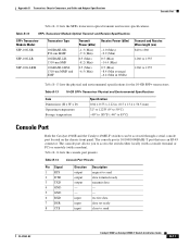
input input input Description request to send OL-21561-02 Catalyst 4948E an Catalyst 4948E-F Switch Installation Guide B-11 receive data data set ready clear to send data terminal ready transmit data - - Table B-13 10-GB SFP+ Transceiver Physical and Environmental Specifications Item Dimensions (H x W x D) Operating ...B-13 lists the physical and environmental specifications for the 10-GB SFP+ transceivers. The console port allows you to 85°C) Console Port Both the Catalyst 4948E and the Catalyst 4948E-F switches can be accessed through a serial console port located on the...
input input input Description request to send OL-21561-02 Catalyst 4948E an Catalyst 4948E-F Switch Installation Guide B-11 receive data data set ready clear to send data terminal ready transmit data - - Table B-13 10-GB SFP+ Transceiver Physical and Environmental Specifications Item Dimensions (H x W x D) Operating ...B-13 lists the physical and environmental specifications for the 10-GB SFP+ transceivers. The console port allows you to 85°C) Console Port Both the Catalyst 4948E and the Catalyst 4948E-F switches can be accessed through a serial console port located on the...
Installation Guide
Page 108
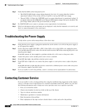
... to start up, this chapter, contact a customer service representative for instructions. Be sure the on /off switch is set correctly and that it is off , there might be a problem with a new power cord...call, have already taken to isolate and resolve the problem Catalyst 4948E and Catalyst 4948E-F Switch Installation Guide C-4 OL-21561-02 It is green when the switch is disabled. If the LED remains off . The port ... in this LED stays orange. • The port LEDs (1-48 plus the 4 SFP/SFP+ ports) are lit: • The STATUS LED flashes orange during diagnostic boot tests.
... to start up, this chapter, contact a customer service representative for instructions. Be sure the on /off switch is set correctly and that it is off , there might be a problem with a new power cord...call, have already taken to isolate and resolve the problem Catalyst 4948E and Catalyst 4948E-F Switch Installation Guide C-4 OL-21561-02 It is green when the switch is disabled. If the LED remains off . The port ... in this LED stays orange. • The port LEDs (1-48 plus the 4 SFP/SFP+ ports) are lit: • The STATUS LED flashes orange during diagnostic boot tests.
