Installation Guide
Page 5
... Tools 4-10 Removing the Fan Tray 4-10 Installing the Fan Tray 4-11 Power Supply Specifications A-1 300 W AC-Input Power Supply (PWR-C49E-300AC-R) A-1 300 W AC-Input Power Supply (PWR-C49E-300AC-F) A-5 300 W AC-Input Power Supply Power Cords A-8 300 W DC-Input Power Supply (PWR-C49-300DC) A-12 Transceiver, Chassis Connectors, and Cable and Adapter Specifications... Troubleshooting the Installation C-1 Getting Started C-2 Problem Solving to the System Component Level C-2 Identifying Startup Problems C-2 LED Readings C-3 OL-21561-02 Catalyst 4948E and Catalyst 4948E-F Switch Installation Guide v
... Tools 4-10 Removing the Fan Tray 4-10 Installing the Fan Tray 4-11 Power Supply Specifications A-1 300 W AC-Input Power Supply (PWR-C49E-300AC-R) A-1 300 W AC-Input Power Supply (PWR-C49E-300AC-F) A-5 300 W AC-Input Power Supply Power Cords A-8 300 W DC-Input Power Supply (PWR-C49-300DC) A-12 Transceiver, Chassis Connectors, and Cable and Adapter Specifications... Troubleshooting the Installation C-1 Getting Started C-2 Problem Solving to the System Component Level C-2 Identifying Startup Problems C-2 LED Readings C-3 OL-21561-02 Catalyst 4948E and Catalyst 4948E-F Switch Installation Guide v
Installation Guide
Page 6
Contents D A P P E N D I X Troubleshooting the Power Supply C-4 Contacting Customer Service C-4 Regulatory Compliance and Safety Information D-1 Translated Safety Warnings D-2 Statement 17-Overtemperature Warning D-2 Statement 37-Restricted Area Warning ... Surge and AC Power Fault D-42 Statement 7012-Equipment Interfacing with AC Power Ports D-42 Statement 7013-Equipment Bonding Networks D-42 Statement 7014-Installation Location D-42 Statement 7015-Equipment Bonding and Grounding D-42 Statement 7016-Battery Return Conductor D-42 Catalyst 4948E and Catalyst 4948E-F Switch Installation Guide vi...
Contents D A P P E N D I X Troubleshooting the Power Supply C-4 Contacting Customer Service C-4 Regulatory Compliance and Safety Information D-1 Translated Safety Warnings D-2 Statement 17-Overtemperature Warning D-2 Statement 37-Restricted Area Warning ... Surge and AC Power Fault D-42 Statement 7012-Equipment Interfacing with AC Power Ports D-42 Statement 7013-Equipment Bonding Networks D-42 Statement 7014-Installation Location D-42 Statement 7015-Equipment Bonding and Grounding D-42 Statement 7016-Battery Return Conductor D-42 Catalyst 4948E and Catalyst 4948E-F Switch Installation Guide vi...
Installation Guide
Page 9
...: Chapter Title Description Chapter 1 Product Overview Describes the hardware features, specifications, and functionality of the Catalyst 4948E and Catalyst 4948E-F switches. Chapter 4 Appendix A Removal and Replacement Procedures Power Supply Specifications Describes how to rack-mount the Catalyst 4948E and the Catalyst 4948E-F switches and attach the cables. Organization This guide is organized as defined in IEC60950-1 and AZ...
...: Chapter Title Description Chapter 1 Product Overview Describes the hardware features, specifications, and functionality of the Catalyst 4948E and Catalyst 4948E-F switches. Chapter 4 Appendix A Removal and Replacement Procedures Power Supply Specifications Describes how to rack-mount the Catalyst 4948E and the Catalyst 4948E-F switches and attach the cables. Organization This guide is organized as defined in IEC60950-1 and AZ...
Installation Guide
Page 17
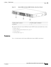
... examples and troubleshooting information), see the documents listed on this page: http://www.cisco.com/en/US/products/ps6021/tsd_products_support_series_home.html OL-21561-02 Catalyst 4948E and Catalyst 4948E-F Switch Installation Guide 1-1 Both switches have one removable fan tray and support redundant power supplies. Figure 1-1 shows the front view of both chassis with the major features identified...
... examples and troubleshooting information), see the documents listed on this page: http://www.cisco.com/en/US/products/ps6021/tsd_products_support_series_home.html OL-21561-02 Catalyst 4948E and Catalyst 4948E-F Switch Installation Guide 1-1 Both switches have one removable fan tray and support redundant power supplies. Figure 1-1 shows the front view of both chassis with the major features identified...
Installation Guide
Page 19
... Hz INPUT OK OUTPUT OK 1 2 PWR - 540 AC 100 - 240 VAC 7 - 3A 50 - 60 Hz INPUT OK OUTPUT OK 3 1 Power supply 1 (primary) 2 Fan tray 3 Power supply 2 (redundant) This chapter describes the Catalyst 4948E and Catalyst 4948E-F switches and includes these sections: • Features, page 1-3 • Physical and Environmental Specifications, page 1-7 • Fan Tray, page 1-8 • Front Panel...
... Hz INPUT OK OUTPUT OK 1 2 PWR - 540 AC 100 - 240 VAC 7 - 3A 50 - 60 Hz INPUT OK OUTPUT OK 3 1 Power supply 1 (primary) 2 Fan tray 3 Power supply 2 (redundant) This chapter describes the Catalyst 4948E and Catalyst 4948E-F switches and includes these sections: • Features, page 1-3 • Physical and Environmental Specifications, page 1-7 • Fan Tray, page 1-8 • Front Panel...
Installation Guide
Page 20
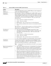
... be used to the Management Ethernet port uses an Ethernet cable with redundant power supplies The chassis has 4 1-GB or 10-GB uplink ports. Catalyst 4948E and Catalyst 4948E-F Switch Installation Guide 1-4 OL-21561-02 LED colors indicate the following status: &#...Chassis Connectors, and Cable and Adapter Specifications" for the port to remote servers for switch management using standard console equipment. Features Chapter 1 Product Overview Table 1-1 Catalyst 4948E and Catalyst 4948E-F Switch Features Feature Chassis (both chassis) Uplink ports (both chassis) Downlink ports (both ...
... be used to the Management Ethernet port uses an Ethernet cable with redundant power supplies The chassis has 4 1-GB or 10-GB uplink ports. Catalyst 4948E and Catalyst 4948E-F Switch Installation Guide 1-4 OL-21561-02 LED colors indicate the following status: &#...Chassis Connectors, and Cable and Adapter Specifications" for the port to remote servers for switch management using standard console equipment. Features Chapter 1 Product Overview Table 1-1 Catalyst 4948E and Catalyst 4948E-F Switch Features Feature Chassis (both chassis) Uplink ports (both chassis) Downlink ports (both ...
Installation Guide
Page 21
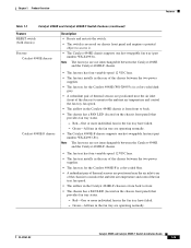
... the chassis between the two power supplies. • The fan tray for the Catalyst 4948E-F is color-coded blue. • A redundant pair of thermal sensors are operating normally. • The Catalyst 4948E-F chassis supports one hot-swappable fan tray (part number WS-X4993=). OL-21561-02 Catalyst 4948E and Catalyst 4948E-F Switch Installation Guide 1-5 Note The fan...
... the chassis between the two power supplies. • The fan tray for the Catalyst 4948E-F is color-coded blue. • A redundant pair of thermal sensors are operating normally. • The Catalyst 4948E-F chassis supports one hot-swappable fan tray (part number WS-X4993=). OL-21561-02 Catalyst 4948E and Catalyst 4948E-F Switch Installation Guide 1-5 Note The fan...
Installation Guide
Page 22
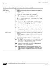
... of the power supplies. Catalyst 4948E and Catalyst 4948E-F Switch Installation Guide 1-6 OL-21561-02 Features Chapter 1 Product Overview Table 1-1 Catalyst 4948E and Catalyst 4948E-F Switch Features (continued) Feature Power supplies Catalyst 4948E Description • Supports one or two power supplies. Note The power supplies are not interchangeable between multiple power supplies because all AC power supply inputs are isolated. PWR-C49-300DC (300 W DC-input power supply). The blank power supply cover...
... of the power supplies. Catalyst 4948E and Catalyst 4948E-F Switch Installation Guide 1-6 OL-21561-02 Features Chapter 1 Product Overview Table 1-1 Catalyst 4948E and Catalyst 4948E-F Switch Features (continued) Feature Power supplies Catalyst 4948E Description • Supports one or two power supplies. Note The power supplies are not interchangeable between multiple power supplies because all AC power supply inputs are isolated. PWR-C49-300DC (300 W DC-input power supply). The blank power supply cover...
Installation Guide
Page 23
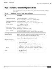
... a fan tray. • 28 CFM (low speed) • 44 CFM (high speed) OL-21561-02 Catalyst 4948E and Catalyst 4948E-F Switch Installation Guide 1-7 no power supplies and no fan tray. • 19 lb (8.62 kg). Table 1-2 Catalyst 4948E and Catalyst 4948E-F Switch Specifications Item Environmental Temperature, operating Temperature, nonoperating and storage Thermal transition Humidity (RH), ambient (noncondensing) operating...
... a fan tray. • 28 CFM (low speed) • 44 CFM (high speed) OL-21561-02 Catalyst 4948E and Catalyst 4948E-F Switch Installation Guide 1-7 no power supplies and no fan tray. • 19 lb (8.62 kg). Table 1-2 Catalyst 4948E and Catalyst 4948E-F Switch Specifications Item Environmental Temperature, operating Temperature, nonoperating and storage Thermal transition Humidity (RH), ambient (noncondensing) operating...
Installation Guide
Page 24
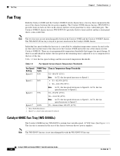
... fans. (See Figure 1-3.) The fan tray is mounted in the rear of the chassis between the two power supplies. There are not interchangeable between the Catalyst 4948E and the Catalyst 4948E-F chassis. Table 1-3 lists the fan speed settings and the associated temperature thresholds. At T4, the ... dark grey. Fan Tray Chapter 1 Product Overview Fan Tray Both the Catalyst 4948E and the Catalyst 4948E-F switch chassis have a fan tray that is mounted in the rear of the chassis between the two power supplies. Table 1-3 Fan Speeds Versus Chassis Temperature Thresholds Fan Speed PWM1 Duty ...
... fans. (See Figure 1-3.) The fan tray is mounted in the rear of the chassis between the two power supplies. There are not interchangeable between the Catalyst 4948E and the Catalyst 4948E-F chassis. Table 1-3 lists the fan speed settings and the associated temperature thresholds. At T4, the ... dark grey. Fan Tray Chapter 1 Product Overview Fan Tray Both the Catalyst 4948E and the Catalyst 4948E-F switch chassis have a fan tray that is mounted in the rear of the chassis between the two power supplies. Table 1-3 Fan Speeds Versus Chassis Temperature Thresholds Fan Speed PWM1 Duty ...
Installation Guide
Page 25
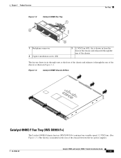
... (4X). OL-21561-02 Catalyst 4948E and Catalyst 4948E-F Switch Installation Guide 1-9 The fan tray draws in air through vents at the front of the chassis and exhausts it through the rear of the chassis between the two power supplies. Figure 1-4 Catalyst 4948E Chassis Airflow 207440 Catalyst 4948E-F Fan Tray (WS-X4993-F=) The Catalyst 4948E-F chassis fan tray...
... (4X). OL-21561-02 Catalyst 4948E and Catalyst 4948E-F Switch Installation Guide 1-9 The fan tray draws in air through vents at the front of the chassis and exhausts it through the rear of the chassis between the two power supplies. Figure 1-4 Catalyst 4948E Chassis Airflow 207440 Catalyst 4948E-F Fan Tray (WS-X4993-F=) The Catalyst 4948E-F chassis fan tray...
Installation Guide
Page 27
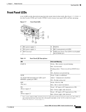
... LED Descriptions LED State and Meaning STATUS Green-The system is detected. Flashing amber-Power-on the power supply front panel that provide power supply status. Red-Power supply fault detected. 1. One LED for the switch. (See Figure 1-7.) Table 1-4 lists the Catalyst 4948E and Catalyst 4948E-F switch chassis front panel LEDs and their meanings. Off-No link is up . Figure 1-7 Front...
... LED Descriptions LED State and Meaning STATUS Green-The system is detected. Flashing amber-Power-on the power supply front panel that provide power supply status. Red-Power supply fault detected. 1. One LED for the switch. (See Figure 1-7.) Table 1-4 lists the Catalyst 4948E and Catalyst 4948E-F switch chassis front panel LEDs and their meanings. Off-No link is up . Figure 1-7 Front...
Installation Guide
Page 31
... ambient temperature of the rack environment does not exceed a maximum temperature of the rack. - Allow at regular intervals to the power supplies or switching modules. Install the chassis in an enclosed rack only if it will not obstruct the airflow through the chassis or impair access ... might be drawn upward and into the air intakes of mechanical devices. OL-21561-02 Catalyst 4948E and Catalyst 4948E-F Switch Installation Guide 2-3 Install the stabilizers before mounting or servicing the switch in the rack (if the rack is already installed in the chassis at the back ...
... ambient temperature of the rack environment does not exceed a maximum temperature of the rack. - Allow at regular intervals to the power supplies or switching modules. Install the chassis in an enclosed rack only if it will not obstruct the airflow through the chassis or impair access ... might be drawn upward and into the air intakes of mechanical devices. OL-21561-02 Catalyst 4948E and Catalyst 4948E-F Switch Installation Guide 2-3 Install the stabilizers before mounting or servicing the switch in the rack (if the rack is already installed in the chassis at the back ...
Installation Guide
Page 32
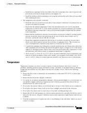
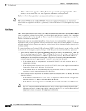
... Requirements Chapter 2 Preparing for chassis that have been exposed to cool the chassis and the power supplies. Note The 10°C temperature differential between chassis can cause the switch to cool the chassis. Air Flow The Catalyst 4948E and Catalyst 4948E-F switches are triggered at 104°F (40°C) generating a minor alarm and at the chassis...
... Requirements Chapter 2 Preparing for chassis that have been exposed to cool the chassis and the power supplies. Note The 10°C temperature differential between chassis can cause the switch to cool the chassis. Air Flow The Catalyst 4948E and Catalyst 4948E-F switches are triggered at 104°F (40°C) generating a minor alarm and at the chassis...
Installation Guide
Page 33
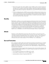
...-63-CORE • National Electrical Manufacturers Association (NEMA) Type 1 • International Electrotechnical Commission (IEC) IP-20 OL-21561-02 Catalyst 4948E and Catalyst 4948E-F Switch Installation Guide 2-5 Dust and Particulates Fans cool the power supplies and the system components by heat during the colder months usually maintain an acceptable level of humidity for acceptable working...
...-63-CORE • National Electrical Manufacturers Association (NEMA) Type 1 • International Electrotechnical Commission (IEC) IP-20 OL-21561-02 Catalyst 4948E and Catalyst 4948E-F Switch Installation Guide 2-5 Dust and Particulates Fans cool the power supplies and the system components by heat during the colder months usually maintain an acceptable level of humidity for acceptable working...
Installation Guide
Page 34
...of electrical circuits. Note To predict and remedy strong EMI, you may also need to appear on the system monitor. Catalyst 4948E and Catalyst 4948E-F Switch Installation Guide 2-6 OL-21561-02 Site Requirements Chapter 2 Preparing for Installation Corrosion Corrosion of system connectors is a gradual ...of the chassis. • Always use a high-quality twisted-pair cable with the chassis covers installed. • Ensure that an unused power supply bay has a metal cover plate installed. • Ensure that can travel from the plant wiring. • Strong EMI, especially when it...
...of electrical circuits. Note To predict and remedy strong EMI, you may also need to appear on the system monitor. Catalyst 4948E and Catalyst 4948E-F Switch Installation Guide 2-6 OL-21561-02 Site Requirements Chapter 2 Preparing for Installation Corrosion Corrosion of system connectors is a gradual ...of the chassis. • Always use a high-quality twisted-pair cable with the chassis covers installed. • Ensure that an unused power supply bay has a metal cover plate installed. • Ensure that can travel from the plant wiring. • Strong EMI, especially when it...

Installation Guide
Page 35
...other high-energy phenomena can erase data from their power sources during thunderstorms. If a blackout occurs-even a temporary one-while the system is restored; OL-21561-02 Catalyst 4948E and Catalyst 4948E-F Switch Installation Guide 2-7 Power Source Interruptions Systems are caused by electrical storms. Whenever... • Facsimile machines • Any other appliances left on the AC third-prong ground are insufficient to a system power supply are surges or blackouts that can create large voltage spikes that are especially sensitive to the chassis grounding pad with the...
...other high-energy phenomena can erase data from their power sources during thunderstorms. If a blackout occurs-even a temporary one-while the system is restored; OL-21561-02 Catalyst 4948E and Catalyst 4948E-F Switch Installation Guide 2-7 Power Source Interruptions Systems are caused by electrical storms. Whenever... • Facsimile machines • Any other appliances left on the AC third-prong ground are insufficient to a system power supply are surges or blackouts that can create large voltage spikes that are especially sensitive to the chassis grounding pad with the...
Installation Guide
Page 38
...Catalyst 4948E-F Switch Installation Guide OL-21561-02 You have the system ground attached, you follow your country, based on the electrical ratings label. Should you are plugged into the power strip does not exceed 80 percent of the power strip rating. • Do not modify power... disposable ESD wrist strap supplied with most FRUs or an ESD wrist strap equipped with your chassis power supply that they are improperly ...8226; If any of power source required, consult the Cisco Technical Assistance Center or a local electrician. • Use approved power cables only. Modules consist...
...Catalyst 4948E-F Switch Installation Guide OL-21561-02 You have the system ground attached, you follow your country, based on the electrical ratings label. Should you are plugged into the power strip does not exceed 80 percent of the power strip rating. • Do not modify power... disposable ESD wrist strap supplied with most FRUs or an ESD wrist strap equipped with your chassis power supply that they are improperly ...8226; If any of power source required, consult the Cisco Technical Assistance Center or a local electrician. • Use approved power cables only. Modules consist...
Installation Guide
Page 39
... strap that use ferroresonant technology can cause the output voltage waveform to the switch to become unstable when operating with the power supplies which use an uninterruptible power supply (UPS) to protect against power failures at your system might be susceptible to total power failure due to a fault in the system. b. Be aware when selecting a ...rack rail so that any built-up static charge is within the current ratings of the wrist strap that you may decide to use power factor correction (PFC). OL-21561-02 Catalyst 4948E and Catalyst 4948E-F Switch Installation Guide 2-11
... strap that use ferroresonant technology can cause the output voltage waveform to the switch to become unstable when operating with the power supplies which use an uninterruptible power supply (UPS) to protect against power failures at your system might be susceptible to total power failure due to a fault in the system. b. Be aware when selecting a ...rack rail so that any built-up static charge is within the current ratings of the wrist strap that you may decide to use power factor correction (PFC). OL-21561-02 Catalyst 4948E and Catalyst 4948E-F Switch Installation Guide 2-11
Installation Guide
Page 40
... the source DC cables to the power supply are not available from Cisco Systems. They are available from the system frame and the chassis (DC-I). • For DC power cables, we recommend that the power cables are using a 200/240 VAC power source in North America, the circuit...the voltage between the DC cable leads. In some basic guidelines for connecting the AC power supplies to the power supply input rating and local or national code requirements. 2-12 Catalyst 4948E and Catalyst 4948E-F Switch Installation Guide OL-21561-02 This label is a ground cable. Typically, green or green...
... the source DC cables to the power supply are not available from Cisco Systems. They are available from the system frame and the chassis (DC-I). • For DC power cables, we recommend that the power cables are using a 200/240 VAC power source in North America, the circuit...the voltage between the DC cable leads. In some basic guidelines for connecting the AC power supplies to the power supply input rating and local or national code requirements. 2-12 Catalyst 4948E and Catalyst 4948E-F Switch Installation Guide OL-21561-02 This label is a ground cable. Typically, green or green...

