
Installation Guide
Page 26
....1D Spanning Tree, Cisco Discovery Protocol (CDP), VTP version 2 with RMON-1 - IEEE 802.1Q VLAN tagging on a per-port basis without the need for in-band management through any switch port through a terminal attached to the console interface - Support for an optional RMON processing module - Performance management information - Catalyst 4948-10GE and Catalyst 4928-10GE Switch Software Features Chapter...
....1D Spanning Tree, Cisco Discovery Protocol (CDP), VTP version 2 with RMON-1 - IEEE 802.1Q VLAN tagging on a per-port basis without the need for in-band management through any switch port through a terminal attached to the console interface - Support for an optional RMON processing module - Performance management information - Catalyst 4948-10GE and Catalyst 4928-10GE Switch Software Features Chapter...
Installation Guide
Page 27
..., Cisco Discovery Protocol (CDP), VTP version 2 with RMON-1 - Embedded CiscoView support 78-18039-02 Catalyst 4900 Series Switch Installation Guide 1-5 Command-line interface (CLI) and Simple Network Management Protocol (SNMP) interfaces consistent with the Catalyst 4500 series switches - Support for in -Q for Gigabit EtherChannel • Catalyst 4500 series management software features include the following : - Chapter 1 Product Overview Catalyst 4948-10GE and Catalyst...
..., Cisco Discovery Protocol (CDP), VTP version 2 with RMON-1 - Embedded CiscoView support 78-18039-02 Catalyst 4900 Series Switch Installation Guide 1-5 Command-line interface (CLI) and Simple Network Management Protocol (SNMP) interfaces consistent with the Catalyst 4500 series switches - Support for in -Q for Gigabit EtherChannel • Catalyst 4500 series management software features include the following : - Chapter 1 Product Overview Catalyst 4948-10GE and Catalyst...
Installation Guide
Page 28
...; (Catalyst 4928-10GE) 28 1000BASE-X Ethernet ports using SFP interfaces • (Catalyst 4948-10GE and Catalyst 4928-10GE) Two 10-Gigabit Ethernet uplink ports using X2 interfaces • Serial console management port using Catalyst 4500 series system software. IEEE 802.1Q - IEEE 802.3 10BASE-T - IEEE 802.3ae - Hardware System Features Chapter 1 Product Overview Hardware System Features The Catalyst 4900 series switches are...
...; (Catalyst 4928-10GE) 28 1000BASE-X Ethernet ports using SFP interfaces • (Catalyst 4948-10GE and Catalyst 4928-10GE) Two 10-Gigabit Ethernet uplink ports using X2 interfaces • Serial console management port using Catalyst 4500 series system software. IEEE 802.1Q - IEEE 802.3 10BASE-T - IEEE 802.3ae - Hardware System Features Chapter 1 Product Overview Hardware System Features The Catalyst 4900 series switches are...
Installation Guide
Page 29
....). it offers the same TCP/IP based management services available using SFP interfaces. Console Port A console serial port (RJ-45) provides for switch management using X2 interfaces. Chapter 1 Product Overview Switch Components Switch Components This section describes the hardware components. Traffic Ports on the Catalyst 4948-10GE There are 28 1000BASE-X Ethernet ports using BOOTP is SFP. Figure...
....). it offers the same TCP/IP based management services available using SFP interfaces. Console Port A console serial port (RJ-45) provides for switch management using X2 interfaces. Chapter 1 Product Overview Switch Components Switch Components This section describes the hardware components. Traffic Ports on the Catalyst 4948-10GE There are 28 1000BASE-X Ethernet ports using BOOTP is SFP. Figure...
Installation Guide
Page 40
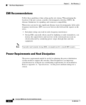
..., can destroy the signal drivers and receivers in the switch and can create an electrical hazard by conducting power surges through lines and into equipment. Catalyst 4900 Series Switch Installation Guide 2-4 78-18039-02 When planning the location of the new system, consider electromagnetic interface (EMI), the distance limitations for an installation. Refer to...
..., can destroy the signal drivers and receivers in the switch and can create an electrical hazard by conducting power surges through lines and into equipment. Catalyst 4900 Series Switch Installation Guide 2-4 78-18039-02 When planning the location of the new system, consider electromagnetic interface (EMI), the distance limitations for an installation. Refer to...
Installation Guide
Page 46
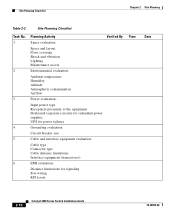
... power supplies UPS for power failures 4 Grounding evaluation: Circuit breaker size 5 Cable and interface equipment evaluation: Cable type Connector type Cable distance limitations Interface equipment (transceivers) 6 EMI evaluation: Distance limitations for signaling Site wiring RFI levels 2-10 Catalyst 4900 Series Switch Installation Guide 78-18039-02 Site Planning Checklist Chapter 2 Site Planning Table 2-2 Site...
... power supplies UPS for power failures 4 Grounding evaluation: Circuit breaker size 5 Cable and interface equipment evaluation: Cable type Connector type Cable distance limitations Interface equipment (transceivers) 6 EMI evaluation: Distance limitations for signaling Site wiring RFI levels 2-10 Catalyst 4900 Series Switch Installation Guide 78-18039-02 Site Planning Checklist Chapter 2 Site Planning Table 2-2 Site...
Installation Guide
Page 48
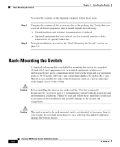
...familiarize yourself with obstructions (such as a power strip) that you ordered, such as network interface cables, transceivers, or special connectors To begin installation, proceed to the "Rack-Mounting the Switch" section on a table top, the added weight may damage the bottom chassis. A standard... depth of 32 inches (81.3 cm). Do not stack more than two on page 3-2. Catalyst 4900 Series Switch Installation Guide 3-2 78-18039-02 Rack-Mounting the Switch Chapter 3 Installing the Switch To verify the contents of the shipping container follow these steps: Step 1 Step 2 Compare ...
...familiarize yourself with obstructions (such as a power strip) that you ordered, such as network interface cables, transceivers, or special connectors To begin installation, proceed to the "Rack-Mounting the Switch" section on a table top, the added weight may damage the bottom chassis. A standard... depth of 32 inches (81.3 cm). Do not stack more than two on page 3-2. Catalyst 4900 Series Switch Installation Guide 3-2 78-18039-02 Rack-Mounting the Switch Chapter 3 Installing the Switch To verify the contents of the shipping container follow these steps: Step 1 Step 2 Compare ...
Installation Guide
Page 61
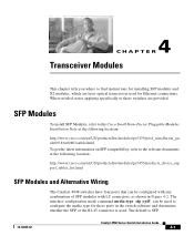
... 4-2. The interface configuration mode command media-type sfp|rj45 can be used . SFP Modules To install SFP Modules, refer to the Cisco Small Form-Factor Pluggable Modules Installation Note at the following location: http://www.cisco.com/en/US/products/hw/modules/ps5455/products_device_sup port_tables_list.html SFP Modules and Alternative Wiring The Catalyst 4948 switches have...
... 4-2. The interface configuration mode command media-type sfp|rj45 can be used . SFP Modules To install SFP Modules, refer to the Cisco Small Form-Factor Pluggable Modules Installation Note at the following location: http://www.cisco.com/en/US/products/hw/modules/ps5455/products_device_sup port_tables_list.html SFP Modules and Alternative Wiring The Catalyst 4948 switches have...
Installation Guide
Page 65
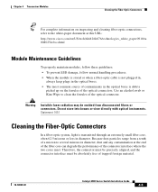
... several microns in diameter. Warning Invisible laser radiation may be absolutely free of the connector interface where the two cores meet. Statement 1051 Cleaning the Fiber-Optic Connectors In a fiber-...an alcohol swab or Kim-Wipe to the white-paper document at this URL: http://www.cisco.com/en/US/tech/tk482/tk876/technologies_white_paper09186a 0080254eba.shtml Module Maintenance Guidelines To properly maintain modules, ... foreign material. 78-18039-02 Catalyst 4900 Series Switch Installation Guide 4-5 Because dust particles range from disconnected fibers or connectors.
... several microns in diameter. Warning Invisible laser radiation may be absolutely free of the connector interface where the two cores meet. Statement 1051 Cleaning the Fiber-Optic Connectors In a fiber-...an alcohol swab or Kim-Wipe to the white-paper document at this URL: http://www.cisco.com/en/US/tech/tk482/tk876/technologies_white_paper09186a 0080254eba.shtml Module Maintenance Guidelines To properly maintain modules, ... foreign material. 78-18039-02 Catalyst 4900 Series Switch Installation Guide 4-5 Because dust particles range from disconnected fibers or connectors.
Installation Guide
Page 82
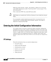
... (IP netmask) • Default gateway (router) • Enable secret password • Enable password • Telnet password Catalyst 4900 Series Switch Installation Guide B-4 78-18039-02 If the switch fails POST, the system LED turns amber. The minimal configuration provided here does not cover most of the features, it simply... allows you need to assign an IP address and other features and interfaces, please refer to display the setup program prompt. Call Cisco Systems if your switch, the PC or terminal displays the bootloader sequence.
... (IP netmask) • Default gateway (router) • Enable secret password • Enable password • Telnet password Catalyst 4900 Series Switch Installation Guide B-4 78-18039-02 If the switch fails POST, the system LED turns amber. The minimal configuration provided here does not cover most of the features, it simply... allows you need to assign an IP address and other features and interfaces, please refer to display the setup program prompt. Call Cisco Systems if your switch, the PC or terminal displays the bootloader sequence.
Installation Guide
Page 84
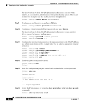
Output suppressed. Switch1 (config)# enable secret SecretPassword Step 9 Configure an enable password, and press Return. Switch1# show ip interface brief Catalyst 4900 Series Switch Installation Guide B-6 78-18039-02 hostname Switch1 ! Switch1 (config)# enable password EnablePassword Step 10 Configure a virtual terminal (Telnet) password, and press Return. Switch1 (config)# password ...
Output suppressed. Switch1 (config)# enable secret SecretPassword Step 9 Configure an enable password, and press Return. Switch1# show ip interface brief Catalyst 4900 Series Switch Installation Guide B-6 78-18039-02 hostname Switch1 ! Switch1 (config)# enable password EnablePassword Step 10 Configure a virtual terminal (Telnet) password, and press Return. Switch1 (config)# password ...
Installation Guide
Page 85
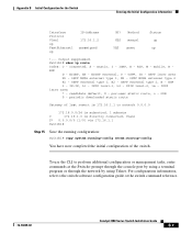
... to network 0.0.0.0 172.16.0.0/24 is subnetted, 1 subnets C 172.16.1.0 is 172.16.1.1 to the switch software configuration guide or the switch command reference. 78-18039-02 Catalyst 4900 Series Switch Installation Guide B-7 Output suppressed. EGP i - ISIS inter area * - IGRP, R - OSPF, IA ...type 1, N2 - OSPF external type 2, E - connected, S - ISIS level-2, ia - Appendix B Initial Configuration for the Switch Entering the Initial Configuration Information Interface Protocol Vlan1 up FastEthernet1 up !--- Switch1# show ip route Codes: C - static, I - ISIS level-1, L2 -
... to network 0.0.0.0 172.16.0.0/24 is subnetted, 1 subnets C 172.16.1.0 is 172.16.1.1 to the switch software configuration guide or the switch command reference. 78-18039-02 Catalyst 4900 Series Switch Installation Guide B-7 Output suppressed. EGP i - ISIS inter area * - IGRP, R - OSPF, IA ...type 1, N2 - OSPF external type 2, E - connected, S - ISIS level-2, ia - Appendix B Initial Configuration for the Switch Entering the Initial Configuration Information Interface Protocol Vlan1 up FastEthernet1 up !--- Switch1# show ip route Codes: C - static, I - ISIS level-1, L2 -

Installation Guide
Page 127
... external Surge Protective Device (SPD) is not sufficient protection in order to connect these interfaces metallically to OSP wiring. The Catalyst 4900 Series Switches are designed for a Common Bonding Network (CBN) installation. These interfaces are designed for use as intra-building interfaces only (Type 2 or Type 4 ports as described in network telecommunication facilities or locations...
... external Surge Protective Device (SPD) is not sufficient protection in order to connect these interfaces metallically to OSP wiring. The Catalyst 4900 Series Switches are designed for a Common Bonding Network (CBN) installation. These interfaces are designed for use as intra-building interfaces only (Type 2 or Type 4 ports as described in network telecommunication facilities or locations...