
Installation Guide
Page 48
...weight may damage the bottom chassis. Rack-Mounting the Switch Chapter 3 Installing the Switch To verify the contents of the shipping container follow these steps: Step 1 Step 2 Compare the contents of 32 inches (81.3 cm). Rack-Mounting the Switch A standard rack-mount kit is included for racks with the proper site and environmental conditions. Catalyst... 4900 Series Switch Installation Guide 3-2 78-18039-02 Caution Before...
...weight may damage the bottom chassis. Rack-Mounting the Switch Chapter 3 Installing the Switch To verify the contents of the shipping container follow these steps: Step 1 Step 2 Compare the contents of 32 inches (81.3 cm). Rack-Mounting the Switch A standard rack-mount kit is included for racks with the proper site and environmental conditions. Catalyst... 4900 Series Switch Installation Guide 3-2 78-18039-02 Caution Before...

Installation Guide
Page 49
... strips or rails, must be 17.75 inches (45.09 cm). - Chapter 3 Installing the Switch Rack-Mounting the Switch Warning To prevent bodily injury when mounting or servicing this unit in a partially filled rack, load ...the rack from becoming top-heavy and tipping over . - The following : • The equipment rack is stable and in the lower half of the rack to support the weight... in no danger of falling over . 78-18039-02 Catalyst 4900 Series Switch Installation Guide 3-3
... strips or rails, must be 17.75 inches (45.09 cm). - Chapter 3 Installing the Switch Rack-Mounting the Switch Warning To prevent bodily injury when mounting or servicing this unit in a partially filled rack, load ...the rack from becoming top-heavy and tipping over . - The following : • The equipment rack is stable and in the lower half of the rack to support the weight... in no danger of falling over . 78-18039-02 Catalyst 4900 Series Switch Installation Guide 3-3

Installation Guide
Page 51
...network connections. If you lift a chassis or any heavy object, follow these guidelines: • Ensure that your footing is solid, and balance the weight of the chassis between your lower back muscles. (See Figure 3-1.) • Always disconnect all external cables before lifting or moving the chassis later ... the chassis: • Number 1, number 2 Phillips, and 3/16-inch flat-blade screwdriver • Antistatic mat or antistatic foam 78-18039-02 Catalyst 4900 Series Switch Installation Guide 3-5 never move suddenly or twist your body as you can avoid moving the chassis.
...network connections. If you lift a chassis or any heavy object, follow these guidelines: • Ensure that your footing is solid, and balance the weight of the chassis between your lower back muscles. (See Figure 3-1.) • Always disconnect all external cables before lifting or moving the chassis later ... the chassis: • Number 1, number 2 Phillips, and 3/16-inch flat-blade screwdriver • Antistatic mat or antistatic foam 78-18039-02 Catalyst 4900 Series Switch Installation Guide 3-5 never move suddenly or twist your body as you can avoid moving the chassis.
Installation Guide
Page 77
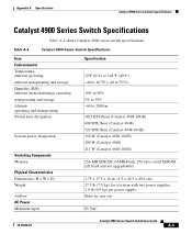
... dissipation Switching Components Memory Physical Characteristics Dimensions (H x W x D) Weight Airflow AC Power Minimum input Specification 32°F (0°C) to 104°F (40°C) -40 to 167°F (-40 to 75°C) 10% to 90% 5% to 95% -60 to 2000 m 1023 BTU/hour (Catalyst 4928-10GE) 600 BTU/hour (Catalyst 4948) 723 BTU/hour (Catalyst 4948-10GE) 150 W (Catalyst 4928-10GE) 200 W (Catalyst 4948) 211 W (Catalyst 4948-10GE...
... dissipation Switching Components Memory Physical Characteristics Dimensions (H x W x D) Weight Airflow AC Power Minimum input Specification 32°F (0°C) to 104°F (40°C) -40 to 167°F (-40 to 75°C) 10% to 90% 5% to 95% -60 to 2000 m 1023 BTU/hour (Catalyst 4928-10GE) 600 BTU/hour (Catalyst 4948) 723 BTU/hour (Catalyst 4948-10GE) 150 W (Catalyst 4928-10GE) 200 W (Catalyst 4948) 211 W (Catalyst 4948-10GE...
Installation Guide
Page 139
... numbers (table) 2-5 airflow site environment 2-2 within the chassis 1-11 alternative wiring 4-1 B blank faceplate 1-13 brackets cable 3-8 mounting 3-6 78-18039-02 INDEX C cable guide 3-8 chassis dimensions A-3 weight A-3 checklist, site planning 2-9 cleaning guidelines 4-7 console port 1-7 connecting to B-2 location 1-7 pinouts A-1 customer service 5-6 D dimensions, chassis A-3 documentation audience i-ix conventions i-xi organization i-ix related...
... numbers (table) 2-5 airflow site environment 2-2 within the chassis 1-11 alternative wiring 4-1 B blank faceplate 1-13 brackets cable 3-8 mounting 3-6 78-18039-02 INDEX C cable guide 3-8 chassis dimensions A-3 weight A-3 checklist, site planning 2-9 cleaning guidelines 4-7 console port 1-7 connecting to B-2 location 1-7 pinouts A-1 customer service 5-6 D dimensions, chassis A-3 documentation audience i-ix conventions i-xi organization i-ix related...

Installation Guide
Page 142
Index traffic ports 1-7 troubleshooting contacting customer service 5-6 initial boot 5-2 methodology 5-2 power supply 5-4, 5-5 startup 5-3 typographical conventions i-xi W warnings translated safety C-2 weight chassis A-3 IN-4 Catalyst 4900 Series Switch Installation Guide 78-18039-02
Index traffic ports 1-7 troubleshooting contacting customer service 5-6 initial boot 5-2 methodology 5-2 power supply 5-4, 5-5 startup 5-3 typographical conventions i-xi W warnings translated safety C-2 weight chassis A-3 IN-4 Catalyst 4900 Series Switch Installation Guide 78-18039-02