
Installation Guide
Page 2
...may radiate radio-frequency energy. This equipment has been tested and found to correct the interference by Cisco Systems, Inc. However, there is not installed in accordance with the specifications in part 15 of Class A devices: This equipment has been tested and found to cause ...harmful interference, in which case users will not occur in accordance with Cisco's installation instructions, it off. NOTWITHSTANDING ANY OTHER WARRANTY...
...may radiate radio-frequency energy. This equipment has been tested and found to correct the interference by Cisco Systems, Inc. However, there is not installed in accordance with the specifications in part 15 of Class A devices: This equipment has been tested and found to cause ...harmful interference, in which case users will not occur in accordance with Cisco's installation instructions, it off. NOTWITHSTANDING ANY OTHER WARRANTY...
Installation Guide
Page 6
... 2-9 Site Planning Checklist 2-9 Installing the Switch 3-1 Verifying the Contents 3-1 Rack-Mounting the Switch 3-2 Rack-Mounting Guidelines 3-3 Lifting the Chassis Safely 3-5 Required Installation Tools 3-5 Rack-Mounting the Switch 3-6 Connecting AC Power to the Switch 3-9 Connecting DC Power to the Switch 3-11 Transceiver Modules 4-1 SFP Modules 4-1... System Component Level 5-2 Identifying Startup Problems 5-3 LED Readings 5-3 Troubleshooting the Power Supply 5-5 Contacting Customer Service 5-6 Specifications A-1 Console Port A-1 Catalyst 4900 Series Switch Installation Guide vi 78-18039-02
... 2-9 Site Planning Checklist 2-9 Installing the Switch 3-1 Verifying the Contents 3-1 Rack-Mounting the Switch 3-2 Rack-Mounting Guidelines 3-3 Lifting the Chassis Safely 3-5 Required Installation Tools 3-5 Rack-Mounting the Switch 3-6 Connecting AC Power to the Switch 3-9 Connecting DC Power to the Switch 3-11 Transceiver Modules 4-1 SFP Modules 4-1... System Component Level 5-2 Identifying Startup Problems 5-3 LED Readings 5-3 Troubleshooting the Power Supply 5-5 Contacting Customer Service 5-6 Specifications A-1 Console Port A-1 Catalyst 4900 Series Switch Installation Guide vi 78-18039-02
Installation Guide
Page 7
B A P P E N D I X C A P P E N D I X Management Port A-2 Catalyst 4900 Series Switch Specifications A-3 Initial Configuration for the Switch B-1 Connecting to the Switch B-2 Starting the Terminal-Emulation Software B-3 Connecting to a Power Source B-3 Entering the Initial Configuration Information B-4 IP Settings B-4 Performing the Initial Configuration B-5 Compliance Information and Translated ... A Notices and Warnings C-46 Class A Notice for FCC C-46 Class A Notice for Canada C-47 Statement 340-Class A Warning for CISPR22 C-47 78-18039-02 Catalyst 4900 Series Switch Installation Guide vii
B A P P E N D I X C A P P E N D I X Management Port A-2 Catalyst 4900 Series Switch Specifications A-3 Initial Configuration for the Switch B-1 Connecting to the Switch B-2 Starting the Terminal-Emulation Software B-3 Connecting to a Power Source B-3 Entering the Initial Configuration Information B-4 IP Settings B-4 Performing the Initial Configuration B-5 Compliance Information and Translated ... A Notices and Warnings C-46 Class A Notice for FCC C-46 Class A Notice for Canada C-47 Statement 340-Class A Warning for CISPR22 C-47 78-18039-02 Catalyst 4900 Series Switch Installation Guide vii
Installation Guide
Page 10
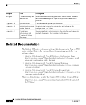
... is available at: http://www.cisco.com/en/US/docs/switches/lan/catalyst4500/release/note/O L_9592.html Catalyst 4900 Series Switch Installation Guide x 78-18039-02 It is a distinct release note for the Catalyst 4900 switches. Refer to help isolate and resolve problems. Specifications Lists the switch system specifications. Related Documentation The Catalyst 4900 series switches use software that will allow...
... is available at: http://www.cisco.com/en/US/docs/switches/lan/catalyst4500/release/note/O L_9592.html Catalyst 4900 Series Switch Installation Guide x 78-18039-02 It is a distinct release note for the Catalyst 4900 switches. Refer to help isolate and resolve problems. Specifications Lists the switch system specifications. Related Documentation The Catalyst 4900 series switches use software that will allow...
Installation Guide
Page 29
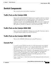
... type for these ports in Appendix A, "Specifications," for the console and management ports. The interface configuration mode command media-type sfp | rj45 can be used . Traffic Ports on the Management port; The Management port on the Catalyst 4948-10GE There are 48 10/100/1000BASE-T Ethernet... last four 10/100/1000BASE-T ports. Traffic Ports on the switches. 78-18039-02 Catalyst 4900 Series Switch Installation Guide 1-7 Figure 1-4 and Figure 1-5 show the location of the management and console ports on the Catalyst 4948 There are 48 10/100/1000BASE-T Ethernet ports using RJ-45...
... type for these ports in Appendix A, "Specifications," for the console and management ports. The interface configuration mode command media-type sfp | rj45 can be used . Traffic Ports on the Management port; The Management port on the Catalyst 4948-10GE There are 48 10/100/1000BASE-T Ethernet... last four 10/100/1000BASE-T ports. Traffic Ports on the switches. 78-18039-02 Catalyst 4900 Series Switch Installation Guide 1-7 Figure 1-4 and Figure 1-5 show the location of the management and console ports on the Catalyst 4948 There are 48 10/100/1000BASE-T Ethernet ports using RJ-45...
Installation Guide
Page 33
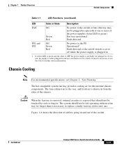
...be necessary to use the CLI for further status information. It may not be plugged in especially if one . Chassis Cooling Note For environmental specifications, see Chapter 2, "Site Planning." Figure 1-8 shows the direction of the power supplies status LED is green) Fan tray operational Fault detected ...LED is green and the other is OFF the power supply is probably not plugged in from the sides of the switch. 78-18039-02 Catalyst 4900 Series Switch Installation Guide 1-11 Caution When the fan tray is removed, internal circuitry is faulty. If it is exposed that should...
...be necessary to use the CLI for further status information. It may not be plugged in especially if one . Chassis Cooling Note For environmental specifications, see Chapter 2, "Site Planning." Figure 1-8 shows the direction of the power supplies status LED is green) Fan tray operational Fault detected ...LED is green and the other is OFF the power supply is probably not plugged in from the sides of the switch. 78-18039-02 Catalyst 4900 Series Switch Installation Guide 1-11 Caution When the fan tray is removed, internal circuitry is faulty. If it is exposed that should...
Installation Guide
Page 34
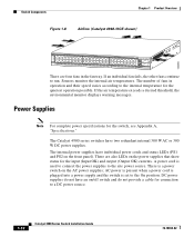
.... Power Supplies Note For complete power specifications for the quietest operation possible. The Catalyst 4900 series switches have an on the power supplies that show status for connection to a DC power source. 1-12 Catalyst 4900 Series Switch Installation Guide 78-18039-02 130085 Switch Components Chapter 1 Product Overview Figure 1-8 Airflow (Catalyst 4948-10GE shown) PS1 PS2 FAN STATUS 1 16...
.... Power Supplies Note For complete power specifications for the quietest operation possible. The Catalyst 4900 series switches have an on the power supplies that show status for connection to a DC power source. 1-12 Catalyst 4900 Series Switch Installation Guide 78-18039-02 130085 Switch Components Chapter 1 Product Overview Figure 1-8 Airflow (Catalyst 4948-10GE shown) PS1 PS2 FAN STATUS 1 16...

Installation Guide
Page 38
... or when placing it on the floor near other equipment, ensure that the exhaust from other equipment. Appendix A, "Specifications," lists the operating and nonoperating environmental site requirements for the switch. This section consists of the chassis. To maintain normal operation and ensure high system availability, maintain an ambient temperature ... in through the sides and exhausted through the rear of the following sections: • Pre-installation Requirements, page 2-3 • Warnings and Cautions, page 2-3 Catalyst 4900 Series Switch Installation Guide 2-2 78-18039-02
... or when placing it on the floor near other equipment, ensure that the exhaust from other equipment. Appendix A, "Specifications," lists the operating and nonoperating environmental site requirements for the switch. This section consists of the chassis. To maintain normal operation and ensure high system availability, maintain an ambient temperature ... in through the sides and exhausted through the rear of the following sections: • Pre-installation Requirements, page 2-3 • Warnings and Cautions, page 2-3 Catalyst 4900 Series Switch Installation Guide 2-2 78-18039-02
Installation Guide
Page 40
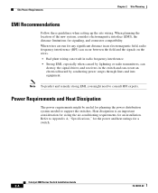
... installation. Refer to consult RFI experts. Catalyst 4900 Series Switch Installation Guide 2-4 78-18039-02 Note To predict and remedy strong EMI, you might be useful for planning the power distribution system needed to support the switches. Heat dissipation is an important consideration for...destroy the signal drivers and receivers in the switch and can create an electrical hazard by conducting power surges through lines and into equipment. Power Requirements and Heat Dissipation The power requirements might need to Appendix A, "Specifications," for the power and heat ratings for...
... installation. Refer to consult RFI experts. Catalyst 4900 Series Switch Installation Guide 2-4 78-18039-02 Note To predict and remedy strong EMI, you might be useful for planning the power distribution system needed to support the switches. Heat dissipation is an important consideration for...destroy the signal drivers and receivers in the switch and can create an electrical hazard by conducting power surges through lines and into equipment. Power Requirements and Heat Dissipation The power requirements might need to Appendix A, "Specifications," for the power and heat ratings for...

Installation Guide
Page 49
... the heaviest component at the bottom of gravity and prevent the rack from the bottom to ensure that the system remains stable. For physical specifications, see Appendix A, "Specifications." - Mount the unit at least 19.25 inches (48.9 cm) but not more than 32 inches (81.3 cm). - Statement 1006 ... to insert the chassis. Ensure that you must be at the bottom of the chassis. The depth of falling over . 78-18039-02 Catalyst 4900 Series Switch Installation Guide 3-3 The chassis height is 1.75 inches (4.45 cm). • The equipment rack is stable and in no danger of the...
... the heaviest component at the bottom of gravity and prevent the rack from the bottom to ensure that the system remains stable. For physical specifications, see Appendix A, "Specifications." - Mount the unit at least 19.25 inches (48.9 cm) but not more than 32 inches (81.3 cm). - Statement 1006 ... to insert the chassis. Ensure that you must be at the bottom of the chassis. The depth of falling over . 78-18039-02 Catalyst 4900 Series Switch Installation Guide 3-3 The chassis height is 1.75 inches (4.45 cm). • The equipment rack is stable and in no danger of the...
Installation Guide
Page 61
..., refer to the relevant documents at the following location: http://www.cisco.com/en/US/products/hw/modules/ps5455/products_device_sup port_tables_list.html SFP Modules and Alternative Wiring The Catalyst 4948 switches have four ports that can be configured with any combination of SFP modules...whether the SFP or the RJ-45 connector is SFP. 78-18039-02 Catalyst 4900 Series Switch Installation Guide 4-1 The default is used for Ethernet connections. Where needed, notes applying specifically to these ports in Figure 4-2. The interface configuration mode command media-type...
..., refer to the relevant documents at the following location: http://www.cisco.com/en/US/products/hw/modules/ps5455/products_device_sup port_tables_list.html SFP Modules and Alternative Wiring The Catalyst 4948 switches have four ports that can be configured with any combination of SFP modules...whether the SFP or the RJ-45 connector is SFP. 78-18039-02 Catalyst 4900 Series Switch Installation Guide 4-1 The default is used for Ethernet connections. Where needed, notes applying specifically to these ports in Figure 4-2. The interface configuration mode command media-type...

Installation Guide
Page 70
...it is more efficient to isolate the problem to determine whether or not it should be doing to what it is operating. Catalyst 4900 Series Switch Installation Guide 5-2 78-18039-02 However, if any of these conditions are not met, use the procedures in the system.... assembly is operating. • System software boots successfully. The switch consists of an overtemperature or overvoltage condition. (It will shut down the system because of the following : • Power supplies are supplying power to a specific system component. Because a startup problem can make if the fan...
...it is more efficient to isolate the problem to determine whether or not it should be doing to what it is operating. Catalyst 4900 Series Switch Installation Guide 5-2 78-18039-02 However, if any of these conditions are not met, use the procedures in the system.... assembly is operating. • System software boots successfully. The switch consists of an overtemperature or overvoltage condition. (It will shut down the system because of the following : • Power supplies are supplying power to a specific system component. Because a startup problem can make if the fan...
Installation Guide
Page 75
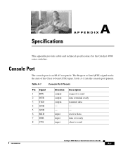
Table A-1 Console Port Pinouts Pin Signal 1 RTS 2 DTR 3 TXD 4 GND 5 GND 6 RXD 7 DSR 8 CTS Direction output output output - - Specifications A A P P E N D I X This appendix provides cable and technical specifications for the Catalyst 4900 series switches. receive data data set ready clear to send data terminal ready transmit data - - input input input Description request to send 78-18039-02...
Table A-1 Console Port Pinouts Pin Signal 1 RTS 2 DTR 3 TXD 4 GND 5 GND 6 RXD 7 DSR 8 CTS Direction output output output - - Specifications A A P P E N D I X This appendix provides cable and technical specifications for the Catalyst 4900 series switches. receive data data set ready clear to send data terminal ready transmit data - - input input input Description request to send 78-18039-02...
Installation Guide
Page 76
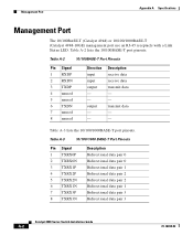
... data pair 1 Bidirectional data pair 2 Bidirectional data pair 2 Bidirectional data pair 1 Bidirectional data pair 3 Bidirectional data pair 3 Catalyst 4900 Series Switch Installation Guide A-2 78-18039-02 Description receive data receive data transmit data - - output - - Table A-2 lists the 10... 5 unused 6 TXDN 7 unused 8 unused Direction input input output - - transmit data - - Management Port Appendix A Specifications Management Port The 10/100BASE-T (Catalyst 4948) or 10/100/1000BASE-T (Catalyst 4948-10GE) management port use an RJ-45 receptacle with a Link Status LED.
... data pair 1 Bidirectional data pair 2 Bidirectional data pair 2 Bidirectional data pair 1 Bidirectional data pair 3 Bidirectional data pair 3 Catalyst 4900 Series Switch Installation Guide A-2 78-18039-02 Description receive data receive data transmit data - - output - - Table A-2 lists the 10... 5 unused 6 TXDN 7 unused 8 unused Direction input input output - - transmit data - - Management Port Appendix A Specifications Management Port The 10/100BASE-T (Catalyst 4948) or 10/100/1000BASE-T (Catalyst 4948-10GE) management port use an RJ-45 receptacle with a Link Status LED.
Installation Guide
Page 77
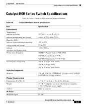
... dissipation Switching Components Memory Physical Characteristics Dimensions (H x W x D) Weight Airflow AC Power Minimum input Specification 32°F (0°C) to 104°F (40°C) -40 to 167°F (-40 to 75°C) 10% to 90% 5% to 95% -60 to 2000 m 1023 BTU/hour (Catalyst 4928-10GE) 600 BTU/hour (Catalyst 4948) 723 BTU/hour (Catalyst 4948-10GE) 150 W (Catalyst 4928-10GE) 200 W (Catalyst 4948) 211 W (Catalyst 4948-10GE...
... dissipation Switching Components Memory Physical Characteristics Dimensions (H x W x D) Weight Airflow AC Power Minimum input Specification 32°F (0°C) to 104°F (40°C) -40 to 167°F (-40 to 75°C) 10% to 90% 5% to 95% -60 to 2000 m 1023 BTU/hour (Catalyst 4928-10GE) 600 BTU/hour (Catalyst 4948) 723 BTU/hour (Catalyst 4948-10GE) 150 W (Catalyst 4928-10GE) 200 W (Catalyst 4948) 211 W (Catalyst 4948-10GE...

Installation Guide
Page 78
Catalyst 4900 Series Switch Specifications Appendix A Specifications Table A-4 Catalyst 4900 Series Switch Specifications (continued) Item Power supply output AC-input AC frequency Output current Peak current Inrush value Output voltage Input KVA rating DC Power Minimum input Power supply output DC-input Output current Peak current Inrush value Output voltage Input KVA rating Specification 300 W 4 A maximum @ ...8 A @ -48 to -60 VDC Cold turn on (PSU off for > 1 hour) - 45 A Hot turn on (PSU on for > 1 hour) - 90 A 12 V 0.4 KVA Catalyst 4900 Series Switch Installation Guide A-4 78-18039-02
Catalyst 4900 Series Switch Specifications Appendix A Specifications Table A-4 Catalyst 4900 Series Switch Specifications (continued) Item Power supply output AC-input AC frequency Output current Peak current Inrush value Output voltage Input KVA rating DC Power Minimum input Power supply output DC-input Output current Peak current Inrush value Output voltage Input KVA rating Specification 300 W 4 A maximum @ ...8 A @ -48 to -60 VDC Cold turn on (PSU off for > 1 hour) - 45 A Hot turn on (PSU on for > 1 hour) - 90 A 12 V 0.4 KVA Catalyst 4900 Series Switch Installation Guide A-4 78-18039-02

Installation Guide
Page 125
... A or Class B), telecomm, and NEBS standards. Table C-1 Class A Regulatory Standards Compliance Specification Regulatory Compliance Safety Standard Products with the CE Marking indicate compliance with national and international standards as described in compliance with the 1999/5/EC directive, which includes the safety and EMC standards listed. The Catalyst 4948, Catalyst 4948-10GE, and Catalyst 4928-10GE switches are in Table C-1.
... A or Class B), telecomm, and NEBS standards. Table C-1 Class A Regulatory Standards Compliance Specification Regulatory Compliance Safety Standard Products with the CE Marking indicate compliance with national and international standards as described in compliance with the 1999/5/EC directive, which includes the safety and EMC standards listed. The Catalyst 4948, Catalyst 4948-10GE, and Catalyst 4928-10GE switches are in Table C-1.

Installation Guide
Page 126
Regulatory Standards Compliance Appendix C Compliance Information and Translated Safety Warnings Table C-1 Class A Regulatory Standards Compliance (continued) Specification EMC Standard EN 60950-1 IEC 60950-1 AS/NZS 60950-1 FCC Part 15 (CFR 47) Class A ICES-003 ... Class A EN55024 EN61000-3-2 EN6100-3-3 EN61000-6-1 EN300 386 KN22 Class A KN immunity series CISPR24 Table C-2 Industry EMC, Safety, and Environmental Standards Specification NEBS Criteria Levels Verizon NEBS Compliance Standard SR-3580 NEBS level 3 (GRC-63-CORE issue 3, GR-1089-CORE , issue 4 Telecommunications Carrier Group...
Regulatory Standards Compliance Appendix C Compliance Information and Translated Safety Warnings Table C-1 Class A Regulatory Standards Compliance (continued) Specification EMC Standard EN 60950-1 IEC 60950-1 AS/NZS 60950-1 FCC Part 15 (CFR 47) Class A ICES-003 ... Class A EN55024 EN61000-3-2 EN6100-3-3 EN61000-6-1 EN300 386 KN22 Class A KN immunity series CISPR24 Table C-2 Industry EMC, Safety, and Environmental Standards Specification NEBS Criteria Levels Verizon NEBS Compliance Standard SR-3580 NEBS level 3 (GRC-63-CORE issue 3, GR-1089-CORE , issue 4 Telecommunications Carrier Group...

Installation Guide
Page 127
...C Compliance Information and Translated Safety Warnings Regulatory Standards Compliance Table C-2 Industry EMC, Safety, and Environmental Standards (continued) Specification Standard Qwest NEBS Compliance TCG Checklist ATT NEBS requirements ATT TP76200 level 3 and TCG Checklist ETSI ETS 300 019-2-1, ... network telecommunication facilities or locations where the National Electric Code applies. 78-18039-02 Catalyst 4900 Series Switch Installation Guide C-41 The Catalyst 4900 Series Switches can be metallically connected to interfaces which connect to the OSP or its wiring. The...
...C Compliance Information and Translated Safety Warnings Regulatory Standards Compliance Table C-2 Industry EMC, Safety, and Environmental Standards (continued) Specification Standard Qwest NEBS Compliance TCG Checklist ATT NEBS requirements ATT TP76200 level 3 and TCG Checklist ETSI ETS 300 019-2-1, ... network telecommunication facilities or locations where the National Electric Code applies. 78-18039-02 Catalyst 4900 Series Switch Installation Guide C-41 The Catalyst 4900 Series Switches can be metallically connected to interfaces which connect to the OSP or its wiring. The...

Installation Guide
Page 130
...]: Toto zariadenie je v zhode so základnými požiadavkami a in ostalimi relevantnimi pogoji Direktive 1999/5/EC. C-44 Catalyst 4900 Series Switch Installation Guide 78-18039-02 European Directives Appendix C Compliance Information and Translated Safety Warnings Polski [Polish]: Português [Portuguese]: [Romanian]:... with Regard to the Directives 73/23/EEC and 89/336/EEC as amended by Directive 93/68/EEC For specifics about which standards have been applied, refer to the Declaration of Conformity. Acest echipament este in conformitate cu cerintele esentiale...
...]: Toto zariadenie je v zhode so základnými požiadavkami a in ostalimi relevantnimi pogoji Direktive 1999/5/EC. C-44 Catalyst 4900 Series Switch Installation Guide 78-18039-02 European Directives Appendix C Compliance Information and Translated Safety Warnings Polski [Polish]: Português [Portuguese]: [Romanian]:... with Regard to the Directives 73/23/EEC and 89/336/EEC as amended by Directive 93/68/EEC For specifics about which standards have been applied, refer to the Declaration of Conformity. Acest echipament este in conformitate cu cerintele esentiale...