
Installation Guide
Page 6
... Electrostatic Discharge Damage 2-9 Site Planning Checklist 2-9 Installing the Switch 3-1 Verifying the Contents 3-1 Rack-Mounting the Switch 3-2 Rack-Mounting Guidelines 3-3 Lifting the Chassis Safely 3-5 Required Installation Tools 3-5 Rack-Mounting the Switch 3-6 Connecting AC Power to the Switch 3-9 Connecting DC Power to the Switch 3-11 Transceiver Modules 4-1 SFP Modules 4-1 SFP Modules and... Problems 5-3 LED Readings 5-3 Troubleshooting the Power Supply 5-5 Contacting Customer Service 5-6 Specifications A-1 Console Port A-1 Catalyst 4900 Series Switch Installation Guide vi 78-18039-02
... Electrostatic Discharge Damage 2-9 Site Planning Checklist 2-9 Installing the Switch 3-1 Verifying the Contents 3-1 Rack-Mounting the Switch 3-2 Rack-Mounting Guidelines 3-3 Lifting the Chassis Safely 3-5 Required Installation Tools 3-5 Rack-Mounting the Switch 3-6 Connecting AC Power to the Switch 3-9 Connecting DC Power to the Switch 3-11 Transceiver Modules 4-1 SFP Modules 4-1 SFP Modules and... Problems 5-3 LED Readings 5-3 Troubleshooting the Power Supply 5-5 Contacting Customer Service 5-6 Specifications A-1 Console Port A-1 Catalyst 4900 Series Switch Installation Guide vi 78-18039-02
Installation Guide
Page 7
...Management Port A-2 Catalyst 4900 Series Switch Specifications A-3 Initial Configuration for the Switch B-1 Connecting to the Switch B-2 Starting the... Terminal-Emulation Software B-3 Connecting to a Power Source B-3 Entering the Initial Configuration Information B-4 IP Settings B-4 Performing the Initial Configuration B-5 Compliance Information and Translated Safety Warnings C-1 Translated Safety Warnings C-2 Statement 1003-DC Power Disconnection C-2 Statement 1004-Installation Instructions C-4 Statement 1006-Chassis Warning for Rack-Mounting...
...Management Port A-2 Catalyst 4900 Series Switch Specifications A-3 Initial Configuration for the Switch B-1 Connecting to the Switch B-2 Starting the... Terminal-Emulation Software B-3 Connecting to a Power Source B-3 Entering the Initial Configuration Information B-4 IP Settings B-4 Performing the Initial Configuration B-5 Compliance Information and Translated Safety Warnings C-1 Translated Safety Warnings C-2 Statement 1003-DC Power Disconnection C-2 Statement 1004-Installation Instructions C-4 Statement 1006-Chassis Warning for Rack-Mounting...

Installation Guide
Page 38
...the minimum or maximum of the following sections: • Pre-installation Requirements, page 2-3 • Warnings and Cautions, page 2-3 Catalyst 4900 Series Switch Installation Guide 2-2 78-18039-02 You can occur. If the airflow is blocked or restricted, or if the intake air is ...environmental anomalies before installation. Site Power Requirements This section describes the installation site power requirements for the switches. The switch environmental monitor can be rack-mounted with other equipment, or when placing it on the floor near other equipment, ensure that the ...
...the minimum or maximum of the following sections: • Pre-installation Requirements, page 2-3 • Warnings and Cautions, page 2-3 Catalyst 4900 Series Switch Installation Guide 2-2 78-18039-02 You can occur. If the airflow is blocked or restricted, or if the intake air is ...environmental anomalies before installation. Site Power Requirements This section describes the installation site power requirements for the switches. The switch environmental monitor can be rack-mounted with other equipment, or when placing it on the floor near other equipment, ensure that the ...

Installation Guide
Page 47
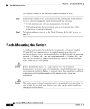
...8226; Rack-Mounting the Switch, page 3-2 • Connecting AC Power to the Switch, page 3-9 • Connecting DC Power to the Switch, page 3-11 Note Before starting the installation procedures in this chapter, complete the site planning checklist in the future. 78-18039-02 Catalyst 4900 Series Switch Installation Guide... 3-1 You will need to move or ship the switch in Chapter 2, "Site Planning," to install the Catalyst 4900 series switch. Verifying the Contents Note Do not discard the shipping...
...8226; Rack-Mounting the Switch, page 3-2 • Connecting AC Power to the Switch, page 3-9 • Connecting DC Power to the Switch, page 3-11 Note Before starting the installation procedures in this chapter, complete the site planning checklist in the future. 78-18039-02 Catalyst 4900 Series Switch Installation Guide... 3-1 You will need to move or ship the switch in Chapter 2, "Site Planning," to install the Catalyst 4900 series switch. Verifying the Contents Note Do not discard the shipping...
Installation Guide
Page 48
... the accessories kit to the packing slip. Catalyst 4900 Series Switch Installation Guide 3-2 78-18039-02 Caution This unit is meant to be rack-mounted, and is not suitable for mounting the switch in a rack, read and follow these guidelines could impair access to the switch. Rack-Mounting the Switch Chapter 3 Installing the Switch To verify the contents of the shipping container...
... the accessories kit to the packing slip. Catalyst 4900 Series Switch Installation Guide 3-2 78-18039-02 Caution This unit is meant to be rack-mounted, and is not suitable for mounting the switch in a rack, read and follow these guidelines could impair access to the switch. Rack-Mounting the Switch Chapter 3 Installing the Switch To verify the contents of the shipping container...

Installation Guide
Page 49
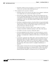
... ensure that you bolt the rack to support the weight and dimensions of falling over . 78-18039-02 Catalyst 4900 Series Switch Installation Guide 3-3 The following : • The equipment rack is provided with stabilizing devices, install the stabilizers before mounting or servicing the unit in ...the lower half of the rack to the top with the heaviest component...
... ensure that you bolt the rack to support the weight and dimensions of falling over . 78-18039-02 Catalyst 4900 Series Switch Installation Guide 3-3 The following : • The equipment rack is provided with stabilizing devices, install the stabilizers before mounting or servicing the unit in ...the lower half of the rack to the top with the heaviest component...
Installation Guide
Page 50
Rack-Mounting the Switch Chapter 3 Installing the Switch - Note that equipment near the top of a wall or cabinet for normal operation and pull it out when necessary for maintenance. Note that a ventilation system in a closed or multiunit rack assembly, the ambient operating temperature of switch assemblies. If the rack...switching modules. Catalyst 4900 Series Switch Installation Guide 3-4 78-18039-02 Ensure that is too powerful might be higher than the ambient room temperature. - If necessary, operate the chassis with stabilizing devices). • The equipment rack...
Rack-Mounting the Switch Chapter 3 Installing the Switch - Note that equipment near the top of a wall or cabinet for normal operation and pull it out when necessary for maintenance. Note that a ventilation system in a closed or multiunit rack assembly, the ambient operating temperature of switch assemblies. If the rack...switching modules. Catalyst 4900 Series Switch Installation Guide 3-4 78-18039-02 Ensure that is too powerful might be higher than the ambient room temperature. - If necessary, operate the chassis with stabilizing devices). • The equipment rack...

Installation Guide
Page 51
Before you install the switch, ensure that your site is properly prepared so that you lift a chassis or any heavy object, follow these guidelines: • Ensure that your footing is ...-18039-02 Catalyst 4900 Series Switch Installation Guide 3-5 If you lift. • Keep your back straight and lift with your legs, not your back. Figure 3-1 Unsafe Lifting Practices H1369a Required Installation Tools The following tools and equipment are required to accommodate power sources and network connections. Chapter 3 Installing the Switch Rack-Mounting the Switch Lifting the...
Before you install the switch, ensure that your site is properly prepared so that you lift a chassis or any heavy object, follow these guidelines: • Ensure that your footing is ...-18039-02 Catalyst 4900 Series Switch Installation Guide 3-5 If you lift. • Keep your back straight and lift with your legs, not your back. Figure 3-1 Unsafe Lifting Practices H1369a Required Installation Tools The following tools and equipment are required to accommodate power sources and network connections. Chapter 3 Installing the Switch Rack-Mounting the Switch Lifting the...

Installation Guide
Page 52
... on the floor or on a sturdy table as close as possible to the outside of a Catalyst 4948-10GE switch. b. Follow these steps to install the switch in a rack: • Rack-mount kit • Tape measure and level Rack-Mounting the Switch Note The illustrations shown are of the rear mounting strip. Measure from the outside of the left front and right front...
... on the floor or on a sturdy table as close as possible to the outside of a Catalyst 4948-10GE switch. b. Follow these steps to install the switch in a rack: • Rack-mount kit • Tape measure and level Rack-Mounting the Switch Note The illustrations shown are of the rear mounting strip. Measure from the outside of the left front and right front...
Installation Guide
Page 53
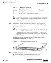
...-head screws provided in the rack-mount kit. (See Figure 3-2.) Figure 3-2 Attaching the L Brackets to the Switch 130086 PS1 PS2 FAN STATUS 1 16 17 32 33 Catalyst WS-C4948 10GE X2-1 X2-2 CON 48 MGT Step 3 Install the chassis in the front of your rack. Chapter 3 Installing the Switch Rack-Mounting the Switch Table 3-1 Quantity 4 4 Rack-Mount Kit Checklist Part Description Received...
...-head screws provided in the rack-mount kit. (See Figure 3-2.) Figure 3-2 Attaching the L Brackets to the Switch 130086 PS1 PS2 FAN STATUS 1 16 17 32 33 Catalyst WS-C4948 10GE X2-1 X2-2 CON 48 MGT Step 3 Install the chassis in the front of your rack. Chapter 3 Installing the Switch Rack-Mounting the Switch Table 3-1 Quantity 4 4 Rack-Mount Kit Checklist Part Description Received...
Installation Guide
Page 54
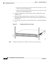
... the chassis between the mounting posts. If the rear of the chassis mount. Use a tape measure and level to the right or left side of the chassis is installed straight and level. Figure 3-3 Installing the Switch in the Rack 130087 PS1 PS2 FAN STATUS 1 16 17 32 33 Catalyst WS-C4948 10GE X2-1 X2-2 CON 48...
... the chassis between the mounting posts. If the rear of the chassis mount. Use a tape measure and level to the right or left side of the chassis is installed straight and level. Figure 3-3 Installing the Switch in the Rack 130087 PS1 PS2 FAN STATUS 1 16 17 32 33 Catalyst WS-C4948 10GE X2-1 X2-2 CON 48...

Installation Guide
Page 128
... the product chassis and the metal surface of the enclosure or rack in compliance with the essential requirements and other nonconductive coatings shall be provided by using thread-forming type mounting screws that remove any paint or nonconductive coatings and establish a metal...med de væsentlige krav og andre [Danish]: relevante bestemmelser i Direktiv 1999/5/EF. C-42 Catalyst 4900 Series Switch Installation Guide 78-18039-02 The nominal DC operating voltage is mounted or to a grounding conductor. The surfaces shall be cleaned and an antioxidant applied before installation. ...
... the product chassis and the metal surface of the enclosure or rack in compliance with the essential requirements and other nonconductive coatings shall be provided by using thread-forming type mounting screws that remove any paint or nonconductive coatings and establish a metal...med de væsentlige krav og andre [Danish]: relevante bestemmelser i Direktiv 1999/5/EF. C-42 Catalyst 4900 Series Switch Installation Guide 78-18039-02 The nominal DC operating voltage is mounted or to a grounding conductor. The surfaces shall be cleaned and an antioxidant applied before installation. ...

Installation Guide
Page 141
...warnings and cautions 2-3 power supply environmental monitoring 1-13 LEDs 1-11, 5-3 overview 1-12 redundancy 1-13 specifications A-4 troubleshooting 5-4, 5-5 R rack-mounting 3-2 redundancy power supply 1-13 78-18039-02 S safety ensuring safety 2-7 overview 2-7 translated safety warnings C-2 screws 3-6 serial number,... documentation i-x specifications AC Power A-3 DC Power A-4 environmental A-3 switching components A-3 startup sequence 5-3 status LED 1-10 system specifications A-1 T temperature thresholds 2-2 terminal-emulation software B-3 Catalyst 4900 Series Switch Installation Guide IN-3
...warnings and cautions 2-3 power supply environmental monitoring 1-13 LEDs 1-11, 5-3 overview 1-12 redundancy 1-13 specifications A-4 troubleshooting 5-4, 5-5 R rack-mounting 3-2 redundancy power supply 1-13 78-18039-02 S safety ensuring safety 2-7 overview 2-7 translated safety warnings C-2 screws 3-6 serial number,... documentation i-x specifications AC Power A-3 DC Power A-4 environmental A-3 switching components A-3 startup sequence 5-3 status LED 1-10 system specifications A-1 T temperature thresholds 2-2 terminal-emulation software B-3 Catalyst 4900 Series Switch Installation Guide IN-3