
Installation Guide
Page 24
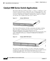
... for high-speed applications. Figure 1-2 Catalyst 4948-10GE Switch 130083 PS1 PS2 FAN STATUS 1 16 17 32 33 Catalyst WS-C4948 10GE X2-1 X2-2 CON 48 MGT The Catalyst 4948-10GE switch has a 136-Gbps, nonblocking, full-duplex switching fabric, providing 102 million packets-per -second of switching capacity for high-performance, high-density edge switching applications. The Catalyst 4948 chassis has 44 10BASE-T/100BASE-TX...
... for high-speed applications. Figure 1-2 Catalyst 4948-10GE Switch 130083 PS1 PS2 FAN STATUS 1 16 17 32 33 Catalyst WS-C4948 10GE X2-1 X2-2 CON 48 MGT The Catalyst 4948-10GE switch has a 136-Gbps, nonblocking, full-duplex switching fabric, providing 102 million packets-per -second of switching capacity for high-performance, high-density edge switching applications. The Catalyst 4948 chassis has 44 10BASE-T/100BASE-TX...
Installation Guide
Page 34
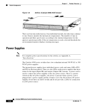
... supplies have individual power cords and status LEDs (PS1 and PS2 on the AC power supplies; 130085 Switch Components Chapter 1 Product Overview Figure 1-8 Airflow (Catalyst 4948-10GE shown) PS1 PS2 FAN STATUS 1 16 17 32 33 Catalyst WS-C4948 10GE X2-1 X2-2 CON 48 MGT There are also LEDs on the power supplies that show status for...
... supplies have individual power cords and status LEDs (PS1 and PS2 on the AC power supplies; 130085 Switch Components Chapter 1 Product Overview Figure 1-8 Airflow (Catalyst 4948-10GE shown) PS1 PS2 FAN STATUS 1 16 17 32 33 Catalyst WS-C4948 10GE X2-1 X2-2 CON 48 MGT There are also LEDs on the power supplies that show status for...
Installation Guide
Page 43
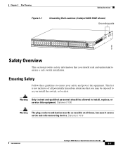
.... Ensuring Safety Follow these guidelines to ensure a safe switch installation. Statement 1030 Warning The plug-socket combination must be alert. Chapter 2 Site Planning Safety Overview Figure 2-1 Grounding Pad Locations (Catalyst 4849-10GE shown) Grounding pads 130180 PS1 PS2 FAN STATUS 1 16 17 32 33 Catalyst WS-C4948 10GE X2-1 X2-2 CON 48 MGT Safety Overview This...
.... Ensuring Safety Follow these guidelines to ensure a safe switch installation. Statement 1030 Warning The plug-socket combination must be alert. Chapter 2 Site Planning Safety Overview Figure 2-1 Grounding Pad Locations (Catalyst 4849-10GE shown) Grounding pads 130180 PS1 PS2 FAN STATUS 1 16 17 32 33 Catalyst WS-C4948 10GE X2-1 X2-2 CON 48 MGT Safety Overview This...
Installation Guide
Page 53
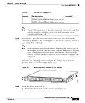
... using the M4 Phillips flat-head screws provided in the rack-mount kit. (See Figure 3-2.) Figure 3-2 Attaching the L Brackets to the Switch 130086 PS1 PS2 FAN STATUS 1 16 17 32 33 Catalyst WS-C4948 10GE X2-1 X2-2 CON 48 MGT Step 3 Install the chassis in the rack as follows (see Figure 3-3): 78-18039-02...
... using the M4 Phillips flat-head screws provided in the rack-mount kit. (See Figure 3-2.) Figure 3-2 Attaching the L Brackets to the Switch 130086 PS1 PS2 FAN STATUS 1 16 17 32 33 Catalyst WS-C4948 10GE X2-1 X2-2 CON 48 MGT Step 3 Install the chassis in the rack as follows (see Figure 3-3): 78-18039-02...
Installation Guide
Page 54
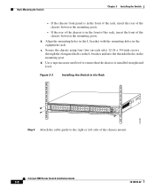
... equipment rack. Rack-Mounting the Switch Chapter 3 Installing the Switch - Align the mounting holes in the L bracket with the mounting holes in the mounting post. If the chassis front panel is in the Rack 130087 PS1 PS2 FAN STATUS 1 16 17 32 33 Catalyst WS-C4948 10GE X2-1 X2-2 CON 48 MGT... Step 4 Attach the cable guide to ensure that the chassis is installed straight and level. Figure 3-3 Installing the Switch in the front of the rack, insert the front of the chassis mount...
... equipment rack. Rack-Mounting the Switch Chapter 3 Installing the Switch - Align the mounting holes in the L bracket with the mounting holes in the mounting post. If the chassis front panel is in the Rack 130087 PS1 PS2 FAN STATUS 1 16 17 32 33 Catalyst WS-C4948 10GE X2-1 X2-2 CON 48 MGT... Step 4 Attach the cable guide to ensure that the chassis is installed straight and level. Figure 3-3 Installing the Switch in the front of the rack, insert the front of the chassis mount...

Installation Guide
Page 55
... must be accessible at this time. Chapter 3 Installing the Switch Connecting AC Power to the Switch" section on page 2-6. Connecting AC Power to the Switch Follow these steps and warnings when connecting power to a Catalyst 4900 series switch: Step 1 Prior to connecting the power supply to a power...(Figure 3-6 shows plug locations.) 78-18039-02 Catalyst 4900 Series Switch Installation Guide 3-9 Proceed to the "Connecting AC Power to the Switch Figure 3-4 Installing the Cable Guide 130089 PS1 PS2 FAN STATUS 1 16 17 32 33 Catalyst WS-C4948 10GE X2-1 X2-2 CON 48 MGT Step 5 Do ...
... must be accessible at this time. Chapter 3 Installing the Switch Connecting AC Power to the Switch" section on page 2-6. Connecting AC Power to the Switch Follow these steps and warnings when connecting power to a Catalyst 4900 series switch: Step 1 Prior to connecting the power supply to a power...(Figure 3-6 shows plug locations.) 78-18039-02 Catalyst 4900 Series Switch Installation Guide 3-9 Proceed to the "Connecting AC Power to the Switch Figure 3-4 Installing the Cable Guide 130089 PS1 PS2 FAN STATUS 1 16 17 32 33 Catalyst WS-C4948 10GE X2-1 X2-2 CON 48 MGT Step 5 Do ...

Installation Guide
Page 63
See the Catalyst 4500 Series Module Installation Guide for operation on an SMF cable is directly coupled to an MMF cable, an effect known as Differential Mode Delay (DMD) might occur. Chapter 4 Transceiver Modules X2 Modules Figure 4-2 Connecting SC Connectors to the X2 Module Catalyst WS-C4948 10GE X2-1 X2-2 CON MGT 130088 If a module designed for more information. 78-18039-02 Catalyst 4900 Series Switch Installation Guide 4-3
See the Catalyst 4500 Series Module Installation Guide for operation on an SMF cable is directly coupled to an MMF cable, an effect known as Differential Mode Delay (DMD) might occur. Chapter 4 Transceiver Modules X2 Modules Figure 4-2 Connecting SC Connectors to the X2 Module Catalyst WS-C4948 10GE X2-1 X2-2 CON MGT 130088 If a module designed for more information. 78-18039-02 Catalyst 4900 Series Switch Installation Guide 4-3
Installation Guide
Page 64
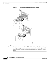
For either the top or bottom connector, forcing a module could potentially damage both the module and the switch. Catalyst 4900 Series Switch Installation Guide 4-4 78-18039-02 X2 Modules Chapter 4 Transceiver Modules Figure 4-3 Installing the 10-Gigabit Ethernet X2 Module Catalyst WS-C4948 10GE CON X1 MGT LINK X2 Catalyst WS-C4948 10GE CON X1 MGT X2 130091 Caution If you attempt to insert the bottom X2 module with the cooling fins pointing up, you will probably permanently damage the connector.
For either the top or bottom connector, forcing a module could potentially damage both the module and the switch. Catalyst 4900 Series Switch Installation Guide 4-4 78-18039-02 X2 Modules Chapter 4 Transceiver Modules Figure 4-3 Installing the 10-Gigabit Ethernet X2 Module Catalyst WS-C4948 10GE CON X1 MGT LINK X2 Catalyst WS-C4948 10GE CON X1 MGT X2 130091 Caution If you attempt to insert the bottom X2 module with the cooling fins pointing up, you will probably permanently damage the connector.


