
Installation Guide
Page 2
... THESE SUPPLIERS ARE PROVIDED "AS IS" WITH ALL FAULTS. IF YOU ARE UNABLE TO LOCATE THE SOFTWARE LICENSE OR LIMITED WARRANTY, CONTACT YOUR CISCO REPRESENTATIVE FOR A COPY. However, there is not installed in this product not authorized by FCC regulations, and you may be required..., AND RECOMMENDATIONS IN THIS MANUAL ARE BELIEVED TO BE ACCURATE BUT ARE PRESENTED WITHOUT WARRANTY OF ANY KIND, EXPRESS OR IMPLIED. THE SOFTWARE LICENSE AND LIMITED WARRANTY FOR THE ACCOMPANYING PRODUCT ARE SET FORTH IN THE INFORMATION PACKET THAT SHIPPED WITH THE PRODUCT AND ARE INCORPORATED HEREIN...
... THESE SUPPLIERS ARE PROVIDED "AS IS" WITH ALL FAULTS. IF YOU ARE UNABLE TO LOCATE THE SOFTWARE LICENSE OR LIMITED WARRANTY, CONTACT YOUR CISCO REPRESENTATIVE FOR A COPY. However, there is not installed in this product not authorized by FCC regulations, and you may be required..., AND RECOMMENDATIONS IN THIS MANUAL ARE BELIEVED TO BE ACCURATE BUT ARE PRESENTED WITHOUT WARRANTY OF ANY KIND, EXPRESS OR IMPLIED. THE SOFTWARE LICENSE AND LIMITED WARRANTY FOR THE ACCOMPANYING PRODUCT ARE SET FORTH IN THE INFORMATION PACKET THAT SHIPPED WITH THE PRODUCT AND ARE INCORPORATED HEREIN...

Installation Guide
Page 5
... 1071-Warning Definition xii Obtaining Documentation and Submitting a Service Request xxi Product Overview 1-1 Catalyst 4900 Series Switch Applications 1-2 Catalyst 4948 Switch Software Features 1-3 Catalyst 4948-10GE and Catalyst 4928-10GE Switch Software Features 1-4 Hardware System Features 1-6 Switch Components 1-7 Traffic Ports on the Catalyst 4948 1-7 Traffic Ports on the Catalyst 4948-10GE 1-7 Traffic Ports on the Catalyst 4928-10GE 1-7 Console Port 1-7 Front Panel LEDs 1-9 Chassis Cooling 1-11 Power Supplies 1-12 Environmental Monitoring...
... 1071-Warning Definition xii Obtaining Documentation and Submitting a Service Request xxi Product Overview 1-1 Catalyst 4900 Series Switch Applications 1-2 Catalyst 4948 Switch Software Features 1-3 Catalyst 4948-10GE and Catalyst 4928-10GE Switch Software Features 1-4 Hardware System Features 1-6 Switch Components 1-7 Traffic Ports on the Catalyst 4948 1-7 Traffic Ports on the Catalyst 4948-10GE 1-7 Traffic Ports on the Catalyst 4928-10GE 1-7 Console Port 1-7 Front Panel LEDs 1-9 Chassis Cooling 1-11 Power Supplies 1-12 Environmental Monitoring...
Installation Guide
Page 7
B A P P E N D I X C A P P E N D I X Management Port A-2 Catalyst 4900 Series Switch Specifications A-3 Initial Configuration for the Switch B-1 Connecting to the Switch B-2 Starting the Terminal-Emulation Software B-3 Connecting to a Power Source B-3 Entering the Initial Configuration Information B-4 IP Settings B-4 Performing the Initial Configuration B-5 Compliance Information and Translated Safety Warnings C-1 ... C-46 Class A Notice for FCC C-46 Class A Notice for Canada C-47 Statement 340-Class A Warning for CISPR22 C-47 78-18039-02 Catalyst 4900 Series Switch Installation Guide vii
B A P P E N D I X C A P P E N D I X Management Port A-2 Catalyst 4900 Series Switch Specifications A-3 Initial Configuration for the Switch B-1 Connecting to the Switch B-2 Starting the Terminal-Emulation Software B-3 Connecting to a Power Source B-3 Entering the Initial Configuration Information B-4 IP Settings B-4 Performing the Initial Configuration B-5 Compliance Information and Translated Safety Warnings C-1 ... C-46 Class A Notice for FCC C-46 Class A Notice for Canada C-47 Statement 340-Class A Warning for CISPR22 C-47 78-18039-02 Catalyst 4900 Series Switch Installation Guide vii
Installation Guide
Page 10
... Warnings States compliance information for your software release: • Catalyst 4500 Series Switch Cisco IOS Software Configuration Guide http://www.cisco.com/en/US/products/hw/switches/ps4324/products_install ation_and_configuration_guides_list.html • Catalyst 4500 Series Switch Cisco IOS Command Reference http://www.cisco.com/en/US/products/hw/switches/ps4324/prod_command _reference_list.html • Catalyst 4500 Series Switch Cisco IOS System Message Guide http://www...
... Warnings States compliance information for your software release: • Catalyst 4500 Series Switch Cisco IOS Software Configuration Guide http://www.cisco.com/en/US/products/hw/switches/ps4324/products_install ation_and_configuration_guides_list.html • Catalyst 4500 Series Switch Cisco IOS Command Reference http://www.cisco.com/en/US/products/hw/switches/ps4324/prod_command _reference_list.html • Catalyst 4500 Series Switch Cisco IOS System Message Guide http://www...
Installation Guide
Page 23
1 C H A P T E R Product Overview This chapter describes the Catalyst 4900 series switches, as well as system features and components. This chapter contains these sections: • Catalyst 4900 Series Switch Applications, page 1-2 • Catalyst 4948 Switch Software Features, page 1-3 • Catalyst 4948-10GE and Catalyst 4928-10GE Switch Software Features, page 1-4 • Hardware System Features, page 1-6 • Hardware System Features, page 1-6 • Switch Components, page 1-7 78-18039-02 Catalyst 4900 Series Switch Installation Guide 1-1
1 C H A P T E R Product Overview This chapter describes the Catalyst 4900 series switches, as well as system features and components. This chapter contains these sections: • Catalyst 4900 Series Switch Applications, page 1-2 • Catalyst 4948 Switch Software Features, page 1-3 • Catalyst 4948-10GE and Catalyst 4928-10GE Switch Software Features, page 1-4 • Hardware System Features, page 1-6 • Hardware System Features, page 1-6 • Switch Components, page 1-7 78-18039-02 Catalyst 4900 Series Switch Installation Guide 1-1

Installation Guide
Page 25
... Catalyst 4948 Switch Software Features The following is an overview of switching capacity for Gigabit EtherChannel 78-18039-02 Catalyst 4900 Series Switch Installation Guide 1-3 See the "Connecting AC Power to the Switch" section on all ports - Chapter 1 Product Overview Catalyst 4948 Switch Software Features Figure 1-3 Catalyst 4928-10GE Switch ...for port aggregation using Port Aggregation Protocol (PAgP) for high-speed applications. Cisco Inter Switch Link (ISL) tagging on page 3-9. All three switches have a removable automatic variable speed fan tray for low noise operation at ...
... Catalyst 4948 Switch Software Features The following is an overview of switching capacity for Gigabit EtherChannel 78-18039-02 Catalyst 4900 Series Switch Installation Guide 1-3 See the "Connecting AC Power to the Switch" section on all ports - Chapter 1 Product Overview Catalyst 4948 Switch Software Features Figure 1-3 Catalyst 4928-10GE Switch ...for port aggregation using Port Aggregation Protocol (PAgP) for high-speed applications. Cisco Inter Switch Link (ISL) tagging on page 3-9. All three switches have a removable automatic variable speed fan tray for low noise operation at ...
Installation Guide
Page 26
... console interface - Support for the first four RMON groups (Ethernet Statistics, Alarms, Events, and History) on all relevant Cisco MIBs - Remote Monitoring (RMON) with the Catalyst 4500 series switches - Embedded CiscoView support Catalyst 4948-10GE and Catalyst 4928-10GE Switch Software Features The following is an overview of -band management over serial lines through SNMP, Telnet client, and Trivial File...
... console interface - Support for the first four RMON groups (Ethernet Statistics, Alarms, Events, and History) on all relevant Cisco MIBs - Remote Monitoring (RMON) with the Catalyst 4500 series switches - Embedded CiscoView support Catalyst 4948-10GE and Catalyst 4928-10GE Switch Software Features The following is an overview of -band management over serial lines through SNMP, Telnet client, and Trivial File...
Installation Guide
Page 27
... Statistics, Alarms, Events, and History) on all relevant Cisco MIBs - Remote Monitoring (RMON) with the Catalyst 4500 series switches - Compatible development of -band management over serial lines through SNMP, Telnet client, and Trivial File Transfer Protocol (TFTP) - Chapter 1 Product Overview Catalyst 4948-10GE and Catalyst 4928-10GE Switch Software Features - Cisco Inter Switch Link (ISL) tagging on a per-port basis without the...
... Statistics, Alarms, Events, and History) on all relevant Cisco MIBs - Remote Monitoring (RMON) with the Catalyst 4500 series switches - Compatible development of -band management over serial lines through SNMP, Telnet client, and Trivial File Transfer Protocol (TFTP) - Chapter 1 Product Overview Catalyst 4948-10GE and Catalyst 4928-10GE Switch Software Features - Cisco Inter Switch Link (ISL) tagging on a per-port basis without the...
Installation Guide
Page 28
... • Serial console management port using Catalyst 4500 series system software. Hardware System Features Chapter 1 Product Overview Hardware System Features The Catalyst 4900 series switches are supported: - The following standards are high-performance dedicated Ethernet switches that fully integrate into the Catalyst family of the Catalyst 4900 series hardware features: • (Catalyst 4948 and 4948-10GE) 48 10BASE-T/100BASE-TX/1000BASE...
... • Serial console management port using Catalyst 4500 series system software. Hardware System Features Chapter 1 Product Overview Hardware System Features The Catalyst 4900 series switches are supported: - The following standards are high-performance dedicated Ethernet switches that fully integrate into the Catalyst family of the Catalyst 4900 series hardware features: • (Catalyst 4948 and 4948-10GE) 48 10BASE-T/100BASE-TX/1000BASE...
Installation Guide
Page 29
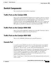
...Catalyst 4928-10GE There are 48 10/100/1000BASE-T Ethernet ports using RJ-45 interfaces and two 10-Gigabit Ethernet uplink ports using SFP interfaces. Traffic Ports on the Management port; it offers the same TCP/IP based management services available using BOOTP is in the switch software... using inband access (Telnet, SNMP, etc.). Figure 1-4 and Figure 1-5 show the location of the management and console ports on the Catalyst 4948-10GE There are 28 1000BASE-X Ethernet ports using standard console equipment. (See Figure 1-4.) A connector pinout table is provided in Appendix A, "...
...Catalyst 4928-10GE There are 48 10/100/1000BASE-T Ethernet ports using RJ-45 interfaces and two 10-Gigabit Ethernet uplink ports using SFP interfaces. Traffic Ports on the Management port; it offers the same TCP/IP based management services available using BOOTP is in the switch software... using inband access (Telnet, SNMP, etc.). Figure 1-4 and Figure 1-5 show the location of the management and console ports on the Catalyst 4948-10GE There are 28 1000BASE-X Ethernet ports using standard console equipment. (See Figure 1-4.) A connector pinout table is provided in Appendix A, "...
Installation Guide
Page 35
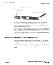
For safety reasons, the AC power supply needs to loss of the power supply and reports status through software. 78-18039-02 Catalyst 4900 Series Switch Installation Guide 1-13 Environmental Monitoring of the Power Supplies Using the environmental monitoring and reporting functions, you can maintain normal system operation by resolving adverse ...
For safety reasons, the AC power supply needs to loss of the power supply and reports status through software. 78-18039-02 Catalyst 4900 Series Switch Installation Guide 1-13 Environmental Monitoring of the Power Supplies Using the environmental monitoring and reporting functions, you can maintain normal system operation by resolving adverse ...
Installation Guide
Page 48
...is meant to be rack-mounted, and is not intended to the system and components. Catalyst 4900 Series Switch Installation Guide 3-2 78-18039-02 Rack-Mounting the Switch Chapter 3 Installing the Switch To verify the contents of the shipping container follow these steps: Step 1 Step 2 ...with the proper site and environmental conditions. Verify that you received all listed equipment, which should include the following: • Switch hardware and software documentation, if ordered • Optional equipment that you ordered, such as a power strip) that could lead to an ...
...is meant to be rack-mounted, and is not intended to the system and components. Catalyst 4900 Series Switch Installation Guide 3-2 78-18039-02 Rack-Mounting the Switch Chapter 3 Installing the Switch To verify the contents of the shipping container follow these steps: Step 1 Step 2 ...with the proper site and environmental conditions. Verify that you received all listed equipment, which should include the following: • Switch hardware and software documentation, if ordered • Optional equipment that you ordered, such as a power strip) that could lead to an ...
Installation Guide
Page 57
...only through the use of a special tool, lock and key, or other system problem, see the command reference publication for your software release. For more information on DC power terminals. If the LEDs or show power command to display the power supply and system ...areas. Statement 1045 Warning Hazardous voltage or energy may be provided as part of the building installation. Statement 1075 78-18039-02 Catalyst 4900 Series Switch Installation Guide 3-11 Statement 1017 Warning This product requires short-circuit (overcurrent) protection, to be present on this command, see Chapter...
...only through the use of a special tool, lock and key, or other system problem, see the command reference publication for your software release. For more information on DC power terminals. If the LEDs or show power command to display the power supply and system ...areas. Statement 1045 Warning Hazardous voltage or energy may be provided as part of the building installation. Statement 1075 78-18039-02 Catalyst 4900 Series Switch Installation Guide 3-11 Statement 1017 Warning This product requires short-circuit (overcurrent) protection, to be present on this command, see Chapter...
Installation Guide
Page 59
...command to a power source. Connect the other system problem, see the command reference publication for troubleshooting information. 78-18039-02 Catalyst 4900 Series Switch Installation Guide 3-13 Verify power supply operation by looking at the front panel power supply LEDs: • The PS1 or ...If both power supplies will be used, make sure they are on this command, see Chapter 5, "Troubleshooting the Installation," for your software release. For more information on different circuits. From the system console, enter the show power command indicate a power or other end of...
...command to a power source. Connect the other system problem, see the command reference publication for troubleshooting information. 78-18039-02 Catalyst 4900 Series Switch Installation Guide 3-13 Verify power supply operation by looking at the front panel power supply LEDs: • The PS1 or ...If both power supplies will be used, make sure they are on this command, see Chapter 5, "Troubleshooting the Installation," for your software release. For more information on different circuits. From the system console, enter the show power command indicate a power or other end of...
Installation Guide
Page 61
... documents at the following location: http://www.cisco.com/en/US/products/hw/modules/ps5455/products_device_sup port_tables_list.html SFP Modules and Alternative Wiring The Catalyst 4948 switches have four ports that can be configured with any combination of SFP modules with LC connectors, as shown in the switch software and determines whether the SFP or the...
... documents at the following location: http://www.cisco.com/en/US/products/hw/modules/ps5455/products_device_sup port_tables_list.html SFP Modules and Alternative Wiring The Catalyst 4948 switches have four ports that can be configured with any combination of SFP modules with LC connectors, as shown in the switch software and determines whether the SFP or the...

Installation Guide
Page 69
... because they also monitor DC-line voltages. 5 C H A P T E R Troubleshooting the Installation This chapter describes how to troubleshoot the switch hardware installation and contains these sections: • Getting Started, page 5-2 • Problem Solving to the System Component Level, page 5-2 •... system has problems starting up, use the information in this chapter to the software configuration guide or the command reference publication. 78-18039-02 Catalyst 4900 Series Switch Installation Guide 5-1 Although temperature conditions above the maximum acceptable level rarely occur at...
... because they also monitor DC-line voltages. 5 C H A P T E R Troubleshooting the Installation This chapter describes how to troubleshoot the switch hardware installation and contains these sections: • Getting Started, page 5-2 • Problem Solving to the System Component Level, page 5-2 •... system has problems starting up, use the information in this chapter to the software configuration guide or the command reference publication. 78-18039-02 Catalyst 4900 Series Switch Installation Guide 5-1 Although temperature conditions above the maximum acceptable level rarely occur at...

Installation Guide
Page 70
... a customer service representative. The first step is to troubleshoot the software. Because a startup problem can make if the fan assembly does not function properly at the initial startup. Catalyst 4900 Series Switch Installation Guide 5-2 78-18039-02 However, if any of these ...conditions are no installation adjustments that the fan assembly is complete, refer to the Software Configuration Guide and the Command Reference publications...
... a customer service representative. The first step is to troubleshoot the software. Because a startup problem can make if the fan assembly does not function properly at the initial startup. Catalyst 4900 Series Switch Installation Guide 5-2 78-18039-02 However, if any of these ...conditions are no installation adjustments that the fan assembly is complete, refer to the Software Configuration Guide and the Command Reference publications...
Installation Guide
Page 72
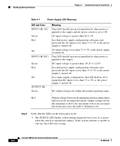
... unit powered) the DC input is less than 73 +/-3V, or the power supply is applied to the supply. If the system software is set to start up, this LED stays orange. Identifying Startup Problems Chapter 5 Troubleshooting the Installation Table 5-1 Power Supply LED Meanings LED...: • The STATUS LED flashes yellow during diagnostic boot tests. In a single supply configuration, the LED shall be off . Catalyst 4900 Series Switch Installation Guide 5-4 78-18039-02 Output voltages below the minimum or above the maximum will not create an output fail alarm. Red Output...
... unit powered) the DC input is less than 73 +/-3V, or the power supply is applied to the supply. If the system software is set to start up, this LED stays orange. Identifying Startup Problems Chapter 5 Troubleshooting the Installation Table 5-1 Power Supply LED Meanings LED...: • The STATUS LED flashes yellow during diagnostic boot tests. In a single supply configuration, the LED shall be off . Catalyst 4900 Series Switch Installation Guide 5-4 78-18039-02 Output voltages below the minimum or above the maximum will not create an output fail alarm. Red Output...

Installation Guide
Page 74
...you as quickly as possible: • Date you received the switch • Chassis serial number (located on a label on the right of the rear of the chassis, see Figure 5-1) • Type of software and release number • Maintenance agreement or warranty information •... Brief description of the problem • Brief explanation of the steps you are unable to isolate and resolve the problem Figure 5-1 Serial Number Location 120534, 781-00289-01 A0 SN: AAANNNNXXXX Catalyst 4900 Series Switch ...
...you as quickly as possible: • Date you received the switch • Chassis serial number (located on a label on the right of the rear of the chassis, see Figure 5-1) • Type of software and release number • Maintenance agreement or warranty information •... Brief description of the problem • Brief explanation of the steps you are unable to isolate and resolve the problem Figure 5-1 Serial Number Location 120534, 781-00289-01 A0 SN: AAANNNNXXXX Catalyst 4900 Series Switch ...

Installation Guide
Page 79
... Ethernet devices. 78-18039-02 Catalyst 4900 Series Switch Installation Guide B-1 Note You need to provide the Category 5 straight-through cables to connect the switch ports to a Power Source, page B-3 4. B A P P E N D I X Initial Configuration for the Switch This chapter provides a quick step...by-step initial setup procedure for more information about setting up your switch with a DC power supply. Starting the Terminal-Emulation Software, page B-3 3. Connecting to the Switch" section on page 3-11 for a switch. Entering the Initial Configuration Information, page B-4 Note If you are...
... Ethernet devices. 78-18039-02 Catalyst 4900 Series Switch Installation Guide B-1 Note You need to provide the Category 5 straight-through cables to connect the switch ports to a Power Source, page B-3 4. B A P P E N D I X Initial Configuration for the Switch This chapter provides a quick step...by-step initial setup procedure for more information about setting up your switch with a DC power supply. Starting the Terminal-Emulation Software, page B-3 3. Connecting to the Switch" section on page 3-11 for a switch. Entering the Initial Configuration Information, page B-4 Note If you are...