
Installation Guide
Page 33
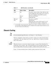
...provides cooling air for further status information. Figure 1-8 shows the direction of airflow going in . Chapter 1 Product Overview Switch Components Table 1-1 LED Functions (continued) LED Color or State Description FAN Off Green Red No power to the switch or fans (the tray may be left operating without a fan tray ... power to the PS Operational1 Fault detected or the on or it is probably not plugged in and out of the switch. 78-18039-02 Catalyst 4900 Series Switch Installation Guide 1-11 The fans exhaust air to use the CLI for the internal chassis components. If it is red,...
...provides cooling air for further status information. Figure 1-8 shows the direction of airflow going in . Chapter 1 Product Overview Switch Components Table 1-1 LED Functions (continued) LED Color or State Description FAN Off Green Red No power to the switch or fans (the tray may be left operating without a fan tray ... power to the PS Operational1 Fault detected or the on or it is probably not plugged in and out of the switch. 78-18039-02 Catalyst 4900 Series Switch Installation Guide 1-11 The fans exhaust air to use the CLI for the internal chassis components. If it is red,...
Installation Guide
Page 34
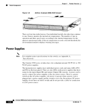
... power supplies do not provide a cable for connection to a DC power source. 1-12 Catalyst 4900 Series Switch Installation Guide 78-18039-02 130085 Switch Components Chapter 1 Product Overview Figure 1-8 Airflow (Catalyst 4948-10GE shown) PS1 PS2 FAN STATUS 1 16 17 32 33 Catalyst WS-C4948 10GE X2-1 X2-2 CON 48 MGT There are also LEDs on the power supplies...
... power supplies do not provide a cable for connection to a DC power source. 1-12 Catalyst 4900 Series Switch Installation Guide 78-18039-02 130085 Switch Components Chapter 1 Product Overview Figure 1-8 Airflow (Catalyst 4948-10GE shown) PS1 PS2 FAN STATUS 1 16 17 32 33 Catalyst WS-C4948 10GE X2-1 X2-2 CON 48 MGT There are also LEDs on the power supplies...

Installation Guide
Page 38
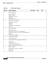
... of the following sections: • Pre-installation Requirements, page 2-3 • Warnings and Cautions, page 2-3 Catalyst 4900 Series Switch Installation Guide 2-2 78-18039-02 However, when mounting a switch in through the sides and exhausted through the rear of 0 to 40° C (32 to protect the...consists of other equipment, ensure that approaches the minimum or maximum of the chassis. To ensure normal operation, maintain ambient airflow. The switch environmental monitor can be rack-mounted with other equipment, or when placing it on the floor near other equipment. Keep the...
... of the following sections: • Pre-installation Requirements, page 2-3 • Warnings and Cautions, page 2-3 Catalyst 4900 Series Switch Installation Guide 2-2 78-18039-02 However, when mounting a switch in through the sides and exhausted through the rear of 0 to 40° C (32 to protect the...consists of other equipment, ensure that approaches the minimum or maximum of the chassis. To ensure normal operation, maintain ambient airflow. The switch environmental monitor can be rack-mounted with other equipment, or when placing it on the floor near other equipment. Keep the...
Installation Guide
Page 46
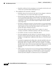
...Date 1 Space evaluation: Space and layout Floor covering Shock and vibration Lighting Maintenance access 2 Environmental evaluation: Ambient temperature Humidity Altitude Atmospheric contamination Airflow 3 Power evaluation: Input power type Receptacle proximity to the equipment Dedicated (separate) circuits for redundant power supplies UPS for power failures 4 ...Connector type Cable distance limitations Interface equipment (transceivers) 6 EMI evaluation: Distance limitations for signaling Site wiring RFI levels 2-10 Catalyst 4900 Series Switch Installation Guide 78-18039-02
...Date 1 Space evaluation: Space and layout Floor covering Shock and vibration Lighting Maintenance access 2 Environmental evaluation: Ambient temperature Humidity Altitude Atmospheric contamination Airflow 3 Power evaluation: Input power type Receptacle proximity to the equipment Dedicated (separate) circuits for redundant power supplies UPS for power failures 4 ...Connector type Cable distance limitations Interface equipment (transceivers) 6 EMI evaluation: Distance limitations for signaling Site wiring RFI levels 2-10 Catalyst 4900 Series Switch Installation Guide 78-18039-02
Installation Guide
Page 50
...temperature. - Note that the ambient temperature of the rack environment does not exceed a maximum temperature of the chassis. - To prevent airflow restriction, allow at least 3 to 4 feet (91.4 to 121.9 cm) of clearance behind the rack for maintenance and removal of... is properly ventilated. - Catalyst 4900 Series Switch Installation Guide 3-4 78-18039-02 Rack-Mounting the Switch Chapter 3 Installing the Switch - Use baffles correctly to the power supplies or switching modules. Route cables away from other equipment will not obstruct the airflow through the chassis or impair...
...temperature. - Note that the ambient temperature of the rack environment does not exceed a maximum temperature of the chassis. - To prevent airflow restriction, allow at least 3 to 4 feet (91.4 to 121.9 cm) of clearance behind the rack for maintenance and removal of... is properly ventilated. - Catalyst 4900 Series Switch Installation Guide 3-4 78-18039-02 Rack-Mounting the Switch Chapter 3 Installing the Switch - Use baffles correctly to the power supplies or switching modules. Route cables away from other equipment will not obstruct the airflow through the chassis or impair...
Installation Guide
Page 77
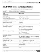
... dissipation Switching Components Memory Physical Characteristics Dimensions (H x W x D) Weight Airflow AC Power Minimum input Specification 32°F (0°C) to 104°F (40°C) -40 to 167°F (-40 to 75°C) 10% to 90% 5% to 95% -60 to 2000 m 1023 BTU/hour (Catalyst 4928-10GE) 600 BTU/hour (Catalyst 4948) 723 BTU/hour (Catalyst 4948-10GE) 150 W (Catalyst 4928-10GE) 200 W (Catalyst 4948) 211 W (Catalyst 4948-10GE...
... dissipation Switching Components Memory Physical Characteristics Dimensions (H x W x D) Weight Airflow AC Power Minimum input Specification 32°F (0°C) to 104°F (40°C) -40 to 167°F (-40 to 75°C) 10% to 90% 5% to 95% -60 to 2000 m 1023 BTU/hour (Catalyst 4928-10GE) 600 BTU/hour (Catalyst 4948) 723 BTU/hour (Catalyst 4948-10GE) 150 W (Catalyst 4928-10GE) 200 W (Catalyst 4948) 211 W (Catalyst 4948-10GE...
Installation Guide
Page 139
... (table) 2-5 airflow site environment 2-2 within the chassis 1-11 alternative wiring 4-1 B blank faceplate 1-13 brackets cable 3-8 mounting 3-6 78-18039-02 INDEX C cable guide 3-8 chassis dimensions A-3 weight A-3 checklist, site planning 2-9 cleaning guidelines 4-7 console port 1-7 connecting to B-2 location 1-7 pinouts A-1 customer service 5-6 D dimensions, chassis A-3 documentation audience i-ix conventions i-xi organization i-ix related i-x Catalyst 4900 Series Switch Installation...
... (table) 2-5 airflow site environment 2-2 within the chassis 1-11 alternative wiring 4-1 B blank faceplate 1-13 brackets cable 3-8 mounting 3-6 78-18039-02 INDEX C cable guide 3-8 chassis dimensions A-3 weight A-3 checklist, site planning 2-9 cleaning guidelines 4-7 console port 1-7 connecting to B-2 location 1-7 pinouts A-1 customer service 5-6 D dimensions, chassis A-3 documentation audience i-ix conventions i-xi organization i-ix related i-x Catalyst 4900 Series Switch Installation...