

Installation Guide
Page 5
...-Warning Definition xii Obtaining Documentation and Submitting a Service Request xxi Product Overview 1-1 Catalyst 4900 Series Switch Applications 1-2 Catalyst 4948 Switch Software Features 1-3 Catalyst 4948-10GE and Catalyst 4928-10GE Switch Software Features 1-4 Hardware System Features 1-6 Switch Components 1-7 Traffic Ports on the Catalyst 4948 1-7 Traffic Ports on the Catalyst 4948-10GE 1-7 Traffic Ports on the Catalyst 4928-10GE 1-7 Console Port 1-7 Front Panel LEDs 1-9 Chassis Cooling 1-11 Power Supplies 1-12 Environmental Monitoring...
...-Warning Definition xii Obtaining Documentation and Submitting a Service Request xxi Product Overview 1-1 Catalyst 4900 Series Switch Applications 1-2 Catalyst 4948 Switch Software Features 1-3 Catalyst 4948-10GE and Catalyst 4928-10GE Switch Software Features 1-4 Hardware System Features 1-6 Switch Components 1-7 Traffic Ports on the Catalyst 4948 1-7 Traffic Ports on the Catalyst 4948-10GE 1-7 Traffic Ports on the Catalyst 4928-10GE 1-7 Console Port 1-7 Front Panel LEDs 1-9 Chassis Cooling 1-11 Power Supplies 1-12 Environmental Monitoring...
Installation Guide
Page 6
... 2-9 Site Planning Checklist 2-9 Installing the Switch 3-1 Verifying the Contents 3-1 Rack-Mounting the Switch 3-2 Rack-Mounting Guidelines 3-3 Lifting the Chassis Safely 3-5 Required Installation Tools 3-5 Rack-Mounting the Switch 3-6 Connecting AC Power to the Switch 3-9 Connecting DC Power to the Switch 3-11 Transceiver Modules 4-1 SFP Modules 4-1...System Component Level 5-2 Identifying Startup Problems 5-3 LED Readings 5-3 Troubleshooting the Power Supply 5-5 Contacting Customer Service 5-6 Specifications A-1 Console Port A-1 Catalyst 4900 Series Switch Installation Guide vi 78-18039-02
... 2-9 Site Planning Checklist 2-9 Installing the Switch 3-1 Verifying the Contents 3-1 Rack-Mounting the Switch 3-2 Rack-Mounting Guidelines 3-3 Lifting the Chassis Safely 3-5 Required Installation Tools 3-5 Rack-Mounting the Switch 3-6 Connecting AC Power to the Switch 3-9 Connecting DC Power to the Switch 3-11 Transceiver Modules 4-1 SFP Modules 4-1...System Component Level 5-2 Identifying Startup Problems 5-3 LED Readings 5-3 Troubleshooting the Power Supply 5-5 Contacting Customer Service 5-6 Specifications A-1 Console Port A-1 Catalyst 4900 Series Switch Installation Guide vi 78-18039-02
Installation Guide
Page 26
...Catalyst 4948-10GE and Catalyst 4928-10GE Switch Software Features The following is an overview of Catalyst 4948-10GE features: • Layer 2, Layer 3, and Layer 4 switching services • Support for 55,000 MAC addresses for Layer 2 switching • Support for in-band management through any switch port through a terminal attached to the console..., Alarms, Events, and History) on all relevant Cisco MIBs - Catalyst 4948-10GE and Catalyst 4928-10GE Switch Software Features Chapter 1 Product Overview • Catalyst 4500 series management software features include the following : ...
...Catalyst 4948-10GE and Catalyst 4928-10GE Switch Software Features The following is an overview of Catalyst 4948-10GE features: • Layer 2, Layer 3, and Layer 4 switching services • Support for 55,000 MAC addresses for Layer 2 switching • Support for in-band management through any switch port through a terminal attached to the console..., Alarms, Events, and History) on all relevant Cisco MIBs - Catalyst 4948-10GE and Catalyst 4928-10GE Switch Software Features Chapter 1 Product Overview • Catalyst 4500 series management software features include the following : ...
Installation Guide
Page 27
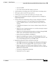
... Protocol (PAgP) for out-of new features with RMON-1 - Q-in -band management through any switch port through a terminal attached to the console interface - Compatible development of -band management over serial lines through SNMP, Telnet client, and Trivial...Support for an optional RMON processing module - Embedded CiscoView support 78-18039-02 Catalyst 4900 Series Switch Installation Guide 1-5 Chapter 1 Product Overview Catalyst 4948-10GE and Catalyst 4928-10GE Switch Software Features - Cisco Inter Switch Link (ISL) tagging on a per-port basis without the need for standard ...
... Protocol (PAgP) for out-of new features with RMON-1 - Q-in -band management through any switch port through a terminal attached to the console interface - Compatible development of -band management over serial lines through SNMP, Telnet client, and Trivial...Support for an optional RMON processing module - Embedded CiscoView support 78-18039-02 Catalyst 4900 Series Switch Installation Guide 1-5 Chapter 1 Product Overview Catalyst 4948-10GE and Catalyst 4928-10GE Switch Software Features - Cisco Inter Switch Link (ISL) tagging on a per-port basis without the need for standard ...
Installation Guide
Page 28
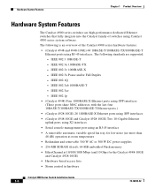
...switches that fully integrate into the Catalyst family of the Catalyst 4900 series hardware features: • (Catalyst 4948 and 4948-10GE) 48 10BASE-T/100BASE-TX/1000BASE-T Ethernet ports using RJ-45 interfaces. IEEE 802.3x Pause and/or Full Duplex - The following is an overview of switches using Catalyst...-TX/1000BASE-T Ethernet ports.) • (Catalyst 4928-10GE) 28 1000BASE-X Ethernet ports using SFP interfaces • (Catalyst 4948-10GE and Catalyst 4928-10GE) Two 10-Gigabit Ethernet uplink ports using X2 interfaces • Serial console management port using an RJ-45 interface &#...
...switches that fully integrate into the Catalyst family of the Catalyst 4900 series hardware features: • (Catalyst 4948 and 4948-10GE) 48 10BASE-T/100BASE-TX/1000BASE-T Ethernet ports using RJ-45 interfaces. IEEE 802.3x Pause and/or Full Duplex - The following is an overview of switches using Catalyst...-TX/1000BASE-T Ethernet ports.) • (Catalyst 4928-10GE) 28 1000BASE-X Ethernet ports using SFP interfaces • (Catalyst 4948-10GE and Catalyst 4928-10GE) Two 10-Gigabit Ethernet uplink ports using X2 interfaces • Serial console management port using an RJ-45 interface &#...
Installation Guide
Page 29
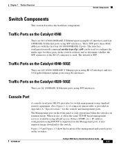
... management ports. it offers the same TCP/IP based management services available using standard console equipment. (See Figure 1-4.) A connector pinout table is in Appendix A, "Specifications," for switch management using inband access (Telnet, SNMP, etc.). Traffic Ports on the Catalyst 4948-10GE There are 48 10/100/1000BASE-T Ethernet ports using RJ-45 interfaces and four...
... management ports. it offers the same TCP/IP based management services available using standard console equipment. (See Figure 1-4.) A connector pinout table is in Appendix A, "Specifications," for switch management using inband access (Telnet, SNMP, etc.). Traffic Ports on the Catalyst 4948-10GE There are 48 10/100/1000BASE-T Ethernet ports using RJ-45 interfaces and four...
Installation Guide
Page 32
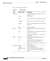
...1-1 describes LED functions. Table 1-1 LED Functions LED STATUS Color or State Green Description At startup, the switch performs a series of diagnostic tests: All tests pass Red A test other than an individual port test ... Port 1-48 Off Green Off Green Off Green Yellow Flashing yellow Off Switch is disabled 10/100 BASE-T console port is in link-up state 10/100 BASE-T console port is in link-down state or not connected There are no blinking...-test indicates faulty port No signal detected or link configuration failure 1-10 Catalyst 4900 Series Switch Installation Guide 78-18039-02
...1-1 describes LED functions. Table 1-1 LED Functions LED STATUS Color or State Green Description At startup, the switch performs a series of diagnostic tests: All tests pass Red A test other than an individual port test ... Port 1-48 Off Green Off Green Off Green Yellow Flashing yellow Off Switch is disabled 10/100 BASE-T console port is in link-up state 10/100 BASE-T console port is in link-down state or not connected There are no blinking...-test indicates faulty port No signal detected or link configuration failure 1-10 Catalyst 4900 Series Switch Installation Guide 78-18039-02
Installation Guide
Page 57
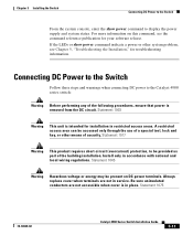
... to the Catalyst 4900 series switch: Warning Before performing any of a special tool, lock and key, or other system problem, see the command reference publication for your software release. Chapter 3 Installing the Switch Connecting DC Power to the Switch From the system console, enter the...supply and system status. Statement 1003 Warning This unit is intended for troubleshooting information. Statement 1075 78-18039-02 Catalyst 4900 Series Switch Installation Guide 3-11 Always replace cover when terminals are not accessible when cover is removed from the DC circuit....
... to the Catalyst 4900 series switch: Warning Before performing any of a special tool, lock and key, or other system problem, see the command reference publication for your software release. Chapter 3 Installing the Switch Connecting DC Power to the Switch From the system console, enter the...supply and system status. Statement 1003 Warning This unit is intended for troubleshooting information. Statement 1075 78-18039-02 Catalyst 4900 Series Switch Installation Guide 3-11 Always replace cover when terminals are not accessible when cover is removed from the DC circuit....
Installation Guide
Page 59
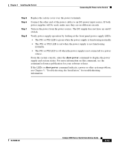
Turn on different circuits. From the system console, enter the show power command indicate a power or other end of the power cables to display the power supply and system status. If both power ... source. Connect the other system problem, see the command reference publication for troubleshooting information. 78-18039-02 Catalyst 4900 Series Switch Installation Guide 3-13 For more information on /off when the power supply is off switch. Verify power supply operation by looking at the front panel power supply LEDs: • The PS1 or...
Turn on different circuits. From the system console, enter the show power command indicate a power or other end of the power cables to display the power supply and system status. If both power ... source. Connect the other system problem, see the command reference publication for troubleshooting information. 78-18039-02 Catalyst 4900 Series Switch Installation Guide 3-13 For more information on /off when the power supply is off switch. Verify power supply operation by looking at the front panel power supply LEDs: • The PS1 or...
Installation Guide
Page 73
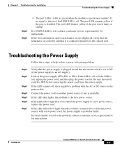
...is red, contact a customer service representative for instructions. 78-18039-02 Catalyst 4900 Series Switch Installation Guide 5-5 If the boot information and system banner are not ...power source with the AC or DC source or the power cable. If the LED still fails to light when the switch is connected to help isolate a power subsystem problem: Step 1 Step 2 Step 3 Step 4 Step 5 Step ...power cord in and that the on /off switch is operational (online). If you connect the power supply to the console port. If the LED is off switch is set correctly and that the terminal is ...
...is red, contact a customer service representative for instructions. 78-18039-02 Catalyst 4900 Series Switch Installation Guide 5-5 If the boot information and system banner are not ...power source with the AC or DC source or the power cable. If the LED still fails to light when the switch is connected to help isolate a power subsystem problem: Step 1 Step 2 Step 3 Step 4 Step 5 Step ...power cord in and that the on /off switch is operational (online). If you connect the power supply to the console port. If the LED is off switch is set correctly and that the terminal is ...
Installation Guide
Page 75
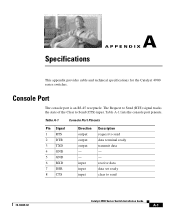
Specifications A A P P E N D I X This appendix provides cable and technical specifications for the Catalyst 4900 series switches. Table A-1 Console Port Pinouts Pin Signal 1 RTS 2 DTR 3 TXD 4 GND 5 GND 6 RXD 7 DSR 8 CTS Direction output output output - - input input input Description request to send 78-18039-02 Catalyst 4900 Series Switch Installation Guide A-1 receive data data set ready clear to send...
Specifications A A P P E N D I X This appendix provides cable and technical specifications for the Catalyst 4900 series switches. Table A-1 Console Port Pinouts Pin Signal 1 RTS 2 DTR 3 TXD 4 GND 5 GND 6 RXD 7 DSR 8 CTS Direction output output output - - input input input Description request to send 78-18039-02 Catalyst 4900 Series Switch Installation Guide A-1 receive data data set ready clear to send...
Installation Guide
Page 80
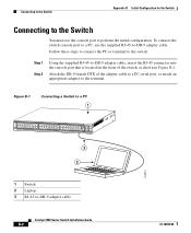
... 1 16 17 32 33 Catalyst 4948 CON 48 MGT 45 46 47 48 3 2 181874 1 Switch 2 Laptop 3 RJ-45-to perform the initial configuration. Attach the DB-9 female DTE of the switch, as shown in Figure B-1. To connect the switch console port to a PC, use the console port to -DB-9 adapter cable Catalyst 4900 Series Switch Installation Guide B-2 78-18039...
... 1 16 17 32 33 Catalyst 4948 CON 48 MGT 45 46 47 48 3 2 181874 1 Switch 2 Laptop 3 RJ-45-to perform the initial configuration. Attach the DB-9 female DTE of the switch, as shown in Figure B-1. To connect the switch console port to a PC, use the console port to -DB-9 adapter cable Catalyst 4900 Series Switch Installation Guide B-2 78-18039...
Installation Guide
Page 81
Catalyst 4900 Series Switch Installation Guide B-3 Step 1 Step 2 Step 3 Start the terminal-emulation program if you are using a DC power supply, see the output display from the power-on the switch rear panel, and then connect the other end of the power cable to a grounded AC ...software-frequently a PC application such as Hyperterminal or ProcommPlus-makes communication between the switch and your PC or terminal possible. Configure the baud rate and character format of the PC or terminal to match these console port default characteristics: • 9600 baud • 8 data bits •...
Catalyst 4900 Series Switch Installation Guide B-3 Step 1 Step 2 Step 3 Start the terminal-emulation program if you are using a DC power supply, see the output display from the power-on the switch rear panel, and then connect the other end of the power cable to a grounded AC ...software-frequently a PC application such as Hyperterminal or ProcommPlus-makes communication between the switch and your PC or terminal possible. Configure the baud rate and character format of the PC or terminal to match these console port default characteristics: • 9600 baud • 8 data bits •...
Installation Guide
Page 85
... You have now completed the initial configuration of last resort is 172.16.1.1 to perform additional configuration or management tasks, enter commands at the Switch> prompt through the console port by using a terminal program or through the network by using Telnet. Switch1# show ip route Codes: C - static, I - ODR P... OK? OSPF, IA - OSPF NSSA external type 2 E1 - ISIS level-1, L2 - EIGRP, EX - For configuration information, refer to the switch software configuration guide or the switch command reference. 78-18039-02 Catalyst 4900 Series Switch Installation Guide B-7
... You have now completed the initial configuration of last resort is 172.16.1.1 to perform additional configuration or management tasks, enter commands at the Switch> prompt through the console port by using a terminal program or through the network by using Telnet. Switch1# show ip route Codes: C - static, I - ODR P... OK? OSPF, IA - OSPF NSSA external type 2 E1 - ISIS level-1, L2 - EIGRP, EX - For configuration information, refer to the switch software configuration guide or the switch command reference. 78-18039-02 Catalyst 4900 Series Switch Installation Guide B-7
Installation Guide
Page 139
... the chassis 1-11 alternative wiring 4-1 B blank faceplate 1-13 brackets cable 3-8 mounting 3-6 78-18039-02 INDEX C cable guide 3-8 chassis dimensions A-3 weight A-3 checklist, site planning 2-9 cleaning guidelines 4-7 console port 1-7 connecting to B-2 location 1-7 pinouts A-1 customer service 5-6 D dimensions, chassis A-3 documentation audience i-ix conventions i-xi organization i-ix related i-x Catalyst 4900 Series Switch Installation Guide IN-1
... the chassis 1-11 alternative wiring 4-1 B blank faceplate 1-13 brackets cable 3-8 mounting 3-6 78-18039-02 INDEX C cable guide 3-8 chassis dimensions A-3 weight A-3 checklist, site planning 2-9 cleaning guidelines 4-7 console port 1-7 connecting to B-2 location 1-7 pinouts A-1 customer service 5-6 D dimensions, chassis A-3 documentation audience i-ix conventions i-xi organization i-ix related i-x Catalyst 4900 Series Switch Installation Guide IN-1