
Software Configuration Guide
Page 11
... Configuring Auto-MDIX on an Interface 10-15 Configuring Power over Ethernet on an Interface 10-16 Adding a Description for an Interface 10-18 Configuring Layer 3 Interfaces 10-19 Configuring the System MTU 10-20 Monitoring and Maintaining the Interfaces 10-22 Monitoring Interface Status 10-22 Clearing and Resetting Interfaces... Configuration 12-8 Creating or Modifying an Ethernet VLAN 12-8 Deleting a VLAN 12-10 Assigning Static-Access Ports to a VLAN 12-11 Contents 78-16156-01 Catalyst 3560 Switch Software Configuration Guide xi
... Configuring Auto-MDIX on an Interface 10-15 Configuring Power over Ethernet on an Interface 10-16 Adding a Description for an Interface 10-18 Configuring Layer 3 Interfaces 10-19 Configuring the System MTU 10-20 Monitoring and Maintaining the Interfaces 10-22 Monitoring Interface Status 10-22 Clearing and Resetting Interfaces... Configuration 12-8 Creating or Modifying an Ethernet VLAN 12-8 Deleting a VLAN 12-10 Assigning Static-Access Ports to a VLAN 12-11 Contents 78-16156-01 Catalyst 3560 Switch Software Configuration Guide xi

Software Configuration Guide
Page 12
...-15 Displaying VLANs 12-16 Configuring VLAN Trunks 12-16 Trunking Overview 12-16 Encapsulation Types 12-18 802.1Q Configuration Considerations 12-18 Default Layer 2 Ethernet Interface VLAN Configuration 12-19 Configuring an Ethernet Interface as a Trunk Port 12-19 Interaction with Other Features 12-20 Configuring a Trunk Port 12...-31 Changing the Retry Count 12-32 Monitoring the VMPS 12-32 Troubleshooting Dynamic-Access Port VLAN Membership 12-33 VMPS Configuration Example 12-33 Catalyst 3560 Switch Software Configuration Guide xii 78-16156-01
...-15 Displaying VLANs 12-16 Configuring VLAN Trunks 12-16 Trunking Overview 12-16 Encapsulation Types 12-18 802.1Q Configuration Considerations 12-18 Default Layer 2 Ethernet Interface VLAN Configuration 12-19 Configuring an Ethernet Interface as a Trunk Port 12-19 Interaction with Other Features 12-20 Configuring a Trunk Port 12...-31 Changing the Retry Count 12-32 Monitoring the VMPS 12-32 Troubleshooting Dynamic-Access Port VLAN Membership 12-33 VMPS Configuration Example 12-33 Catalyst 3560 Switch Software Configuration Guide xii 78-16156-01

Software Configuration Guide
Page 21
... IP ACL Entries 27-25 ACL Logging 27-25 Creating Named MAC Extended ACLs 27-26 Applying a MAC ACL to a Layer 2 Interface 27-28 Configuring VLAN Maps 27-29 VLAN Map Configuration Guidelines 27-29 Creating a VLAN Map 27-30 Examples ... ACLs 27-36 Guidelines 27-36 Examples of Router ACLs and VLAN Maps Applied to VLANs 27-37 ACLs and Switched Packets 27-37 ACLs and Bridged Packets 27-38 ACLs and Routed Packets 27-38 ACLs and Multicast Packets 27-... on QoS ACLs 28-7 Classification Based on Class Maps and Policy Maps 28-7 Policing and Marking 28-8 Catalyst 3560 Switch Software Configuration Guide xxi
... IP ACL Entries 27-25 ACL Logging 27-25 Creating Named MAC Extended ACLs 27-26 Applying a MAC ACL to a Layer 2 Interface 27-28 Configuring VLAN Maps 27-29 VLAN Map Configuration Guidelines 27-29 Creating a VLAN Map 27-30 Examples ... ACLs 27-36 Guidelines 27-36 Examples of Router ACLs and VLAN Maps Applied to VLANs 27-37 ACLs and Switched Packets 27-37 ACLs and Bridged Packets 27-38 ACLs and Routed Packets 27-38 ACLs and Multicast Packets 27-... on QoS ACLs 28-7 Classification Based on Class Maps and Policy Maps 28-7 Policing and Marking 28-8 Catalyst 3560 Switch Software Configuration Guide xxi

Software Configuration Guide
Page 23
...Other Features 29-6 Load Balancing and Forwarding Methods 29-6 Configuring EtherChannels 29-8 Default EtherChannel Configuration 29-9 EtherChannel Configuration Guidelines 29-9 Configuring Layer 2 EtherChannels 29-10 Configuring Layer 3 EtherChannels 29-12 Creating Port-Channel Logical Interfaces 29-12 Configuring the Physical Interfaces 29-13 Configuring EtherChannel Load Balancing 29-15 Configuring...17 Configuring the LACP System Priority 29-18 Configuring the LACP Port Priority 29-19 Displaying EtherChannel, PAgP, and LACP Status 29-20 Catalyst 3560 Switch Software Configuration Guide xxiii
...Other Features 29-6 Load Balancing and Forwarding Methods 29-6 Configuring EtherChannels 29-8 Default EtherChannel Configuration 29-9 EtherChannel Configuration Guidelines 29-9 Configuring Layer 2 EtherChannels 29-10 Configuring Layer 3 EtherChannels 29-12 Creating Port-Channel Logical Interfaces 29-12 Configuring the Physical Interfaces 29-13 Configuring EtherChannel Load Balancing 29-15 Configuring...17 Configuring the LACP System Priority 29-18 Configuring the LACP Port Priority 29-19 Displaying EtherChannel, PAgP, and LACP Status 29-20 Catalyst 3560 Switch Software Configuration Guide xxiii

Software Configuration Guide
Page 29
... Connectivity 35-11 Preventing Autonegotiation Mismatches 35-12 Troubleshooting Power over Ethernet Switch Ports 35-12 SFP Module Security and Identification 35-12 Using Ping 35-13 Understanding Ping 35-13 Executing Ping 35-13 Using Layer 2 Traceroute 35-14 Understanding Layer 2 Traceroute 35-14 Usage Guidelines 35-15 Displaying the Physical Path... Debug and Error Message Output 35-19 Using the show platform forward Command 35-19 Using the crashinfo File 35-22 Contents 78-16156-01 Catalyst 3560 Switch Software Configuration Guide xxix
... Connectivity 35-11 Preventing Autonegotiation Mismatches 35-12 Troubleshooting Power over Ethernet Switch Ports 35-12 SFP Module Security and Identification 35-12 Using Ping 35-13 Understanding Ping 35-13 Executing Ping 35-13 Using Layer 2 Traceroute 35-14 Understanding Layer 2 Traceroute 35-14 Usage Guidelines 35-15 Displaying the Physical Path... Debug and Error Message Output 35-19 Using the show platform forward Command 35-19 Using the crashinfo File 35-22 Contents 78-16156-01 Catalyst 3560 Switch Software Configuration Guide xxix
Software Configuration Guide
Page 33
... multicast routing, and fallback bridging). The SMI provides Layer 2+ features including access control lists (ACLs), quality of switches. It does not provide detailed information about the standard Cisco IOS Release 12.1 commands, refer to the CMS online help, which is integrated with the Catalyst 3560 switch. Preface Audience This guide is for the networking professional...
... multicast routing, and fallback bridging). The SMI provides Layer 2+ features including access control lists (ACLs), quality of switches. It does not provide detailed information about the standard Cisco IOS Release 12.1 commands, refer to the CMS online help, which is integrated with the Catalyst 3560 switch. Preface Audience This guide is for the networking professional...
Software Configuration Guide
Page 39
...IP version 4 (IPv4). It includes all features described in this chapter and in this release. 78-16156-01 Catalyst 3560 Switch Software Configuration Guide 1-1 Some features noted in the "Layer 3 Features" section on both the SMI and EMI. Overview CH A P T E R 1 This chapter ... the EMI. • Enhanced multilayer image (EMI), which provides Layer 2+ features (enterprise-class intelligent services). To distinguish it from Cisco.com. These features include access control lists (ACLs), quality of the SMI and EMI. Features The Catalyst 3560 switches are supported on page 1-8.
...IP version 4 (IPv4). It includes all features described in this chapter and in this release. 78-16156-01 Catalyst 3560 Switch Software Configuration Guide 1-1 Some features noted in the "Layer 3 Features" section on both the SMI and EMI. Overview CH A P T E R 1 This chapter ... the EMI. • Enhanced multilayer image (EMI), which provides Layer 2+ features (enterprise-class intelligent services). To distinguish it from Cisco.com. These features include access control lists (ACLs), quality of the SMI and EMI. Features The Catalyst 3560 switches are supported on page 1-8.

Software Configuration Guide
Page 40
...requiring the cryptographic [that is, supports encryption] versions of the SMI and EMI) • QoS and CoS Features, page 1-7 • Layer 3 Features, page 1-8 (includes features requiring the EMI) • Power over Ethernet (PoE) Features, page 1-8 • Monitoring Features...that guides you to provide only the minimum required information to identify link information between switches. - and switch-level monitoring and troubleshooting, and multiple switch software upgrades. - Catalyst 3560 Switch Software Configuration Guide 1-2 78-16156-01 Viewing a topology of service (QoS). ...
...requiring the cryptographic [that is, supports encryption] versions of the SMI and EMI) • QoS and CoS Features, page 1-7 • Layer 3 Features, page 1-8 (includes features requiring the EMI) • Power over Ethernet (PoE) Features, page 1-8 • Monitoring Features...that guides you to provide only the minimum required information to identify link information between switches. - and switch-level monitoring and troubleshooting, and multiple switch software upgrades. - Catalyst 3560 Switch Software Configuration Guide 1-2 78-16156-01 Viewing a topology of service (QoS). ...

Software Configuration Guide
Page 41
...mode on all switch ports for optimizing bandwidth • Automatic-medium-dependent interface crossover (Auto-MDIX) capability on 10/100 Mbps interfaces and on forwarding unknown Layer 2 unknown unicast, multicast, and bridged broadcast traffic • Cisco Group Management ... send multicast streams in the IGMP forwarding table • Switch Database Management (SDM) templates for user-selected features 78-16156-01 Catalyst 3560 Switch Software Configuration Guide 1-3 Chapter 1 Overview Features • Switch clustering technology for a list of their geographic proximity and...
...mode on all switch ports for optimizing bandwidth • Automatic-medium-dependent interface crossover (Auto-MDIX) capability on 10/100 Mbps interfaces and on forwarding unknown Layer 2 unknown unicast, multicast, and bridged broadcast traffic • Cisco Group Management ... send multicast streams in the IGMP forwarding table • Switch Database Management (SDM) templates for user-selected features 78-16156-01 Catalyst 3560 Switch Software Configuration Guide 1-3 Chapter 1 Overview Features • Switch clustering technology for a list of their geographic proximity and...

Software Configuration Guide
Page 43
...VLAN Query Protocol (VQP) for dynamic VLAN membership 78-16156-01 Catalyst 3560 Switch Software Configuration Guide 1-5 Per-VLAN spanning-tree plus (PVST+) for preventing switches outside the network core from becoming designated ports because of a failure...Cisco RPS 675 for enhancing power reliability VLAN Features • Support for up to 1005 VLANs for assigning users to VLANs associated with appropriate network resources, traffic patterns, and bandwidth • Support for VLAN IDs in PVST+, rapid-PVST+, and MSTP mode: - Availability Features • HSRP for command switch and Layer...
...VLAN Query Protocol (VQP) for dynamic VLAN membership 78-16156-01 Catalyst 3560 Switch Software Configuration Guide 1-5 Per-VLAN spanning-tree plus (PVST+) for preventing switches outside the network core from becoming designated ports because of a failure...Cisco RPS 675 for enhancing power reliability VLAN Features • Support for up to 1005 VLANs for assigning users to VLANs associated with appropriate network resources, traffic patterns, and bandwidth • Support for VLAN IDs in PVST+, rapid-PVST+, and MSTP mode: - Availability Features • HSRP for command switch and Layer...
Software Configuration Guide
Page 44
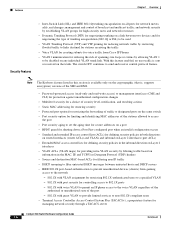
...from Cisco IP Phones • VLAN1 minimization for reducing the risk of broadcast and multicast traffic; Features Chapter 1 Overview Security Features • Inter-Switch Link (ISL) and IEEE 802.1Q trunking encapsulation on all ports for managing network security through a TACACS server Catalyst 3560 Switch ...both directions on routed interfaces (router ACLs) and VLANs and inbound on Layer 2 interfaces (port ACLs) • Extended MAC access control lists for defining security policies in the inbound direction on Layer 2 interfaces • VLAN ACLs (VLAN maps) for providing intra-...
...from Cisco IP Phones • VLAN1 minimization for reducing the risk of broadcast and multicast traffic; Features Chapter 1 Overview Security Features • Inter-Switch Link (ISL) and IEEE 802.1Q trunking encapsulation on all ports for managing network security through a TACACS server Catalyst 3560 Switch ...both directions on routed interfaces (router ACLs) and VLANs and inbound on Layer 2 interfaces (port ACLs) • Extended MAC access control lists for defining security policies in the inbound direction on Layer 2 interfaces • VLAN ACLs (VLAN maps) for providing intra-...
Software Configuration Guide
Page 46
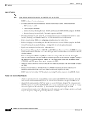
... combination of ports provide an average of 7.7 W of power at the same time, up to a maximum switch power output of power on the EMI. • HSRP for Layer 3 router redundancy • IP routing protocols for load balancing and for forwarding UDP broadcasts, including IP address...Ethernet (PoE) Features • Ability to provide power to connected Cisco pre-standard and IEEE 802.3af-compliant powered devices from all 10/100 Ethernet ports if the switch senses that there is available Catalyst 3560 Switch Software Configuration Guide 1-8 78-16156-01 Interior Gateway Routing Protocol ...
... combination of ports provide an average of 7.7 W of power at the same time, up to a maximum switch power output of power on the EMI. • HSRP for Layer 3 router redundancy • IP routing protocols for load balancing and for forwarding UDP broadcasts, including IP address...Ethernet (PoE) Features • Ability to provide power to connected Cisco pre-standard and IEEE 802.3af-compliant powered devices from all 10/100 Ethernet ports if the switch senses that there is available Catalyst 3560 Switch Software Configuration Guide 1-8 78-16156-01 Interior Gateway Routing Protocol ...

Software Configuration Guide
Page 47
...the switch, refer to the hardware installation guide. Chapter 4, "Assigning the Switch IP Address and Default Gateway" Chapter 5, "Clustering Switches" Chapter 6, "Administering the Switch" Chapter 9, "Configuring 802.1X Port-Based Authentication" 78-16156-01 Catalyst 3560 Switch Software Configuration Guide 1-9 and switch-level... issues, and time-out events • Layer 2 traceroute to identify the physical path that a packet takes from a source device to a destination device Default Settings After Initial Switch Configuration The switch is designed for plug-and-play operation, ...
...the switch, refer to the hardware installation guide. Chapter 4, "Assigning the Switch IP Address and Default Gateway" Chapter 5, "Clustering Switches" Chapter 6, "Administering the Switch" Chapter 9, "Configuring 802.1X Port-Based Authentication" 78-16156-01 Catalyst 3560 Switch Software Configuration Guide 1-9 and switch-level... issues, and time-out events • Layer 2 traceroute to identify the physical path that a packet takes from a source device to a destination device Default Settings After Initial Switch Configuration The switch is designed for plug-and-play operation, ...

Software Configuration Guide
Page 48
... Chapter 1 Overview Table 1-1 Default Settings After Initial Switch Configuration (continued) Feature Port parameters Operating mode Interface speed and duplex mode Auto-MDIX Flow control Power over Ethernet (PoE) SmartPort macros Default Setting Layer 2 (switchport) Autonegotiate Disabled Off Auto None defined VLANs Default VLAN VLAN trunking Trunk encapsulation VTP... Chapter 20, "Configuring Port-Based Traffic Control" Chapter 21, "Configuring CDP" Chapter 22, "Configuring UDLD" Chapter 23, "Configuring SPAN and RSPAN" 1-10 Catalyst 3560 Switch Software Configuration Guide 78-16156-01
... Chapter 1 Overview Table 1-1 Default Settings After Initial Switch Configuration (continued) Feature Port parameters Operating mode Interface speed and duplex mode Auto-MDIX Flow control Power over Ethernet (PoE) SmartPort macros Default Setting Layer 2 (switchport) Autonegotiate Disabled Off Auto None defined VLANs Default VLAN VLAN trunking Trunk encapsulation VTP... Chapter 20, "Configuring Port-Based Traffic Control" Chapter 21, "Configuring CDP" Chapter 22, "Configuring UDLD" Chapter 23, "Configuring SPAN and RSPAN" 1-10 Catalyst 3560 Switch Software Configuration Guide 78-16156-01
Software Configuration Guide
Page 51
... on the switches. Catalyst PoE switch ports automatically detect any Cisco pre-standard and IEEE 802.3af-compliant powered devices that support at higher speeds Use the Catalyst Long-Reach Ethernet (LRE) switches to provide up to receive power. 78-16156-01 Catalyst 3560 Switch Software Configuration ...station in one VLAN needs to communicate with an end station in another VLAN, a router or Layer 3 switch routes the traffic to Catalyst Power over Ethernet (PoE) switches, 802.1P/Q QoS gives voice traffic forwarding-priority over existing infrastructure, such as existing telephone ...
... on the switches. Catalyst PoE switch ports automatically detect any Cisco pre-standard and IEEE 802.3af-compliant powered devices that support at higher speeds Use the Catalyst Long-Reach Ethernet (LRE) switches to provide up to receive power. 78-16156-01 Catalyst 3560 Switch Software Configuration ...station in one VLAN needs to communicate with an end station in another VLAN, a router or Layer 3 switch routes the traffic to Catalyst Power over Ethernet (PoE) switches, 802.1P/Q QoS gives voice traffic forwarding-priority over existing infrastructure, such as existing telephone ...

Software Configuration Guide
Page 52
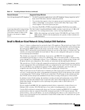
...network traffic profiles evolve, switches in accordance with workstations running Cisco SoftPhone software Aironet wireless access points Large Network Using Catalyst 3560 Switches Switches in the wiring closet have redundant uplink connections to the backbone switches, with each switch has IGMP snooping enabled ...each switch. In the wiring closet, each uplink port configured as the Catalyst 6500 switches, to aggregate up to trust the CoS value, the DSCP value, or the IP precedence. Each switch provides inter-VLAN routing. These switches also have traditionally been Layer ...
...network traffic profiles evolve, switches in accordance with workstations running Cisco SoftPhone software Aironet wireless access points Large Network Using Catalyst 3560 Switches Switches in the wiring closet have redundant uplink connections to the backbone switches, with each switch has IGMP snooping enabled ...each switch. In the wiring closet, each uplink port configured as the Catalyst 6500 switches, to aggregate up to trust the CoS value, the DSCP value, or the IP precedence. Each switch provides inter-VLAN routing. These switches also have traditionally been Layer ...

Software Configuration Guide
Page 54
...of data over distances of up to Go Next Before configuring the switch, review these sections for long-distance transmissions is sent at wavelengths from 1470 to travel . Where to the Cisco CWDM GBIC and CWDM SFP Installation Note. The CWDM OADM modules ...module, data is 1550 nm. Figure 1-3 Long-Distance, High-Bandwidth Transport Configuration Access layer Aggregation layer 95750 8 Gbps Catalyst switches CWDM OADM modules Eight 1-Gbps connections CWDM OADM modules Catalyst 4500 multilayer switches Where to 393,701 feet (74.5 miles or 120 km). A common wavelength used ...
...of data over distances of up to Go Next Before configuring the switch, review these sections for long-distance transmissions is sent at wavelengths from 1470 to travel . Where to the Cisco CWDM GBIC and CWDM SFP Installation Note. The CWDM OADM modules ...module, data is 1550 nm. Figure 1-3 Long-Distance, High-Bandwidth Transport Configuration Access layer Aggregation layer 95750 8 Gbps Catalyst switches CWDM OADM modules Eight 1-Gbps connections CWDM OADM modules Catalyst 4500 multilayer switches Where to 393,701 feet (74.5 miles or 120 km). A common wavelength used ...

Software Configuration Guide
Page 87
Figure 4-2 Relay Device Used in Autoconfiguration Switch (DHCP client) Cisco router (Relay) 10.0.0.1 10.0.0.2 20.0.0.1 20.0.0.2 20.0.0.3 20.0.0.4 49068 DHCP server TFTP server DNS server Obtaining Configuration Files Depending on your switch. The switch sends a broadcast message to a TFTP server to retrieve the named ...its host name. 78-16156-01 Catalyst 3560 Switch Software Configuration Guide 4-7 If the host name is not specified in the DHCP reply. For more information, see the "Routed Ports" section on page 10-3 and the "Configuring Layer 3 Interfaces" section on page 10-...
Figure 4-2 Relay Device Used in Autoconfiguration Switch (DHCP client) Cisco router (Relay) 10.0.0.1 10.0.0.2 20.0.0.1 20.0.0.2 20.0.0.3 20.0.0.4 49068 DHCP server TFTP server DNS server Obtaining Configuration Files Depending on your switch. The switch sends a broadcast message to a TFTP server to retrieve the named ...its host name. 78-16156-01 Catalyst 3560 Switch Software Configuration Guide 4-7 If the host name is not specified in the DHCP reply. For more information, see the "Routed Ports" section on page 10-3 and the "Configuring Layer 3 Interfaces" section on page 10-...

Software Configuration Guide
Page 100
... which ones can be distributed across a Layer 2 or Layer 3 (if your cluster is using a Catalyst 3550, Catalyst 3560, or Catalyst 3750 switch as a Layer 3 router between the Layer 2 switches in the cluster) network. One or more switches can belong to the software configuration guide for the Catalyst 1900, Catalyst 2820, Catalyst 2900 XL, Catalyst 2950, and Catalyst 3500 XL switches. All communication with cluster members. These...
... which ones can be distributed across a Layer 2 or Layer 3 (if your cluster is using a Catalyst 3550, Catalyst 3560, or Catalyst 3750 switch as a Layer 3 router between the Layer 2 switches in the cluster) network. One or more switches can belong to the software configuration guide for the Catalyst 1900, Catalyst 2820, Catalyst 2900 XL, Catalyst 2950, and Catalyst 3500 XL switches. All communication with cluster members. These...

Software Configuration Guide
Page 106
... the cluster command switch and cluster member switch 7 is VLAN 9. The Layer 3 cluster command switch in Figure 5-5 can discover the switches in VLANs 9 and 62 but not the switch in VLAN 4. Planning a Switch Cluster Chapter 5 Clustering Switches The cluster command switch and standby command switch in Figure 5-4 (assuming they are Catalyst 2970, Catalyst 3550, Catalyst 3560, or Catalyst 3750 cluster command switches) have ports assigned...
... the cluster command switch and cluster member switch 7 is VLAN 9. The Layer 3 cluster command switch in Figure 5-5 can discover the switches in VLANs 9 and 62 but not the switch in VLAN 4. Planning a Switch Cluster Chapter 5 Clustering Switches The cluster command switch and standby command switch in Figure 5-4 (assuming they are Catalyst 2970, Catalyst 3550, Catalyst 3560, or Catalyst 3750 cluster command switches) have ports assigned...
