
Software Configuration Guide
Page 22
... 28-47 Configuring the CoS-to-DSCP Map 28-47 Configuring the IP-Precedence-to-DSCP Map 28-48 Configuring the Policed-DSCP Map 28-49 Configuring the DSCP-to-CoS Map 28-50 Configuring the DSCP-to-DSCP-Mutation Map 28-51 Catalyst 3560 Switch Software Configuration Guide xxii 78-16156-01
... 28-47 Configuring the CoS-to-DSCP Map 28-47 Configuring the IP-Precedence-to-DSCP Map 28-48 Configuring the Policed-DSCP Map 28-49 Configuring the DSCP-to-CoS Map 28-50 Configuring the DSCP-to-DSCP-Mutation Map 28-51 Catalyst 3560 Switch Software Configuration Guide xxii 78-16156-01

Software Configuration Guide
Page 28
... a Metric Offset to the DVMRP Route 32-48 Monitoring and Maintaining IP Multicast Routing 32-49 Clearing Caches, Tables, and Databases 32-50 Displaying System and ...a Filter 33-12 Using TTL to Limit the Multicast Data Sent in SA Messages 33-14 Controlling Source Information that Your Switch Receives 33-14 Configuring an MSDP Mesh Group 33-16 Shutting Down an MSDP Peer 33-16 Including a Bordering PIM Dense-...34-5 Changing the VLAN-Bridge Spanning-Tree Priority 34-6 Changing the Interface Priority 34-6 Assigning a Path Cost 34-7 xxviii Catalyst 3560 Switch Software Configuration Guide 78-16156-01
... a Metric Offset to the DVMRP Route 32-48 Monitoring and Maintaining IP Multicast Routing 32-49 Clearing Caches, Tables, and Databases 32-50 Displaying System and ...a Filter 33-12 Using TTL to Limit the Multicast Data Sent in SA Messages 33-14 Controlling Source Information that Your Switch Receives 33-14 Configuring an MSDP Mesh Group 33-16 Shutting Down an MSDP Peer 33-16 Including a Bordering PIM Dense-...34-5 Changing the VLAN-Bridge Spanning-Tree Priority 34-6 Changing the Interface Priority 34-6 Assigning a Path Cost 34-7 xxviii Catalyst 3560 Switch Software Configuration Guide 78-16156-01
Software Configuration Guide
Page 46
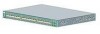
... (inter-VLAN routing) for full Layer 3 routing between two or more VLANs, allowing each 10/100 port; 48-port PoE switch provides 15.4 W of power to any 24 of the 48 10/100 ports, or any combination of ports provide an average of 7.7 W of power at the same time... clients Power over Ethernet (PoE) Features • Ability to provide power to connected Cisco pre-standard and IEEE 802.3af-compliant powered devices from all 10/100 Ethernet ports if the switch senses that there is available Catalyst 3560 Switch Software Configuration Guide 1-8 78-16156-01 RIP versions 1 and 2 - Features Chapter...
... (inter-VLAN routing) for full Layer 3 routing between two or more VLANs, allowing each 10/100 port; 48-port PoE switch provides 15.4 W of power to any 24 of the 48 10/100 ports, or any combination of ports provide an average of 7.7 W of power at the same time... clients Power over Ethernet (PoE) Features • Ability to provide power to connected Cisco pre-standard and IEEE 802.3af-compliant powered devices from all 10/100 Ethernet ports if the switch senses that there is available Catalyst 3560 Switch Software Configuration Guide 1-8 78-16156-01 RIP versions 1 and 2 - Features Chapter...

Software Configuration Guide
Page 118
... Switches stack10 (cisco WS-C3750-24TS, HC, .. TRS (cisco WS-C37xx-24, HC, ...) stack1 (cisco WS-3750-48, CC, 0) G-M-C3550-24 (cisco WS-C3550-24, H Active command switch. Once entered, this information cannot be a valid IP address in the cluster. Standby command switch....summary includes information such as the active command switch. Enter the command-switch password. Must be changed. 93336 Verifying a Switch Cluster When you can also display port and switch statistics from a cluster member switch. 5-20 Catalyst 3560 Switch Software Configuration Guide 78-16156-01
... Switches stack10 (cisco WS-C3750-24TS, HC, .. TRS (cisco WS-C37xx-24, HC, ...) stack1 (cisco WS-3750-48, CC, 0) G-M-C3550-24 (cisco WS-C3550-24, H Active command switch. Once entered, this information cannot be a valid IP address in the cluster. Standby command switch....summary includes information such as the active command switch. Enter the command-switch password. Must be changed. 93336 Verifying a Switch Cluster When you can also display port and switch statistics from a cluster member switch. 5-20 Catalyst 3560 Switch Software Configuration Guide 78-16156-01

Software Configuration Guide
Page 150
Displays the MAC address table information for the specified interface. Then the IP datagram is enabled on Cisco.com. 6-28 Catalyst 3560 Switch Software Configuration Guide 78-16156-01 Encapsulation of IP datagrams and ARP requests and replies on IEEE 802 networks other than Ethernet is specified by...with the corresponding media or MAC addresses and the VLAN ID. For CLI procedures, refer to the table do not age and must determine the 48-bit MAC or the local data link address of that device. Displays the MAC address table information for the specified VLAN. The process of ...
Displays the MAC address table information for the specified interface. Then the IP datagram is enabled on Cisco.com. 6-28 Catalyst 3560 Switch Software Configuration Guide 78-16156-01 Encapsulation of IP datagrams and ARP requests and replies on IEEE 802 networks other than Ethernet is specified by...with the corresponding media or MAC addresses and the VLAN ID. For CLI procedures, refer to the table do not age and must determine the 48-bit MAC or the local data link address of that device. Displays the MAC address table information for the specified VLAN. The process of ...

Software Configuration Guide
Page 232
... both the Cisco pre-standard PoE method and the IEEE 802.3af PoE standard. A powered device can receive redundant power when it is still powering the device whether the device is being powered by the switch or receiving power from an AC power source. 10-16 Catalyst 3560 Switch Software Configuration Guide ... 10/100 port provides 15.4 W of power at the same time, up Link down Beginning in the configuration file. On a 48-port PoE switch, any 24 of the 48 10/100 ports provide 15.4 W of power, or any combination of ports provide an average of 7.7 W of power. If a device being powered...
... both the Cisco pre-standard PoE method and the IEEE 802.3af PoE standard. A powered device can receive redundant power when it is still powering the device whether the device is being powered by the switch or receiving power from an AC power source. 10-16 Catalyst 3560 Switch Software Configuration Guide ... 10/100 port provides 15.4 W of power at the same time, up Link down Beginning in the configuration file. On a 48-port PoE switch, any 24 of the 48 10/100 ports provide 15.4 W of power, or any combination of ports provide an average of 7.7 W of power. If a device being powered...

Software Configuration Guide
Page 317
.... • For priority, the range is optional. All other values are 0, 16, 32, 48, 64, 80, 96, 112, 128, 144, 160, 176, 192, 208, 224, and 240. The range is 1 to confirm the configuration. 78-16156-01 Catalyst 3560 Switch Software Configuration Guide 15-17 Valid values are rejected. Return to put into...
.... • For priority, the range is optional. All other values are 0, 16, 32, 48, 64, 80, 96, 112, 128, 144, 160, 176, 192, 208, 224, and 240. The range is 1 to confirm the configuration. 78-16156-01 Catalyst 3560 Switch Software Configuration Guide 15-17 Valid values are rejected. Return to put into...

Software Configuration Guide
Page 339
...priority of 16. Otherwise, you can use the no spanning-tree mst instance-id port-priority interface configuration command. 78-16156-01 Catalyst 3560 Switch Software Configuration Guide 16-17 If all interfaces have the same priority value, the MSTP puts the interface with the lowest interface ...-config Purpose Enter global configuration mode. The port-channel range is optional. Beginning in the forwarding state and blocks the other values are 0, 16, 32, 48, 64, 80, 96, 112, 128, 144, 160, 176, 192, 208, 224, and 240. Step 1 Step 2 Step 3 Step 4 Step 5 Step 6 Command...
...priority of 16. Otherwise, you can use the no spanning-tree mst instance-id port-priority interface configuration command. 78-16156-01 Catalyst 3560 Switch Software Configuration Guide 16-17 If all interfaces have the same priority value, the MSTP puts the interface with the lowest interface ...-config Purpose Enter global configuration mode. The port-channel range is optional. Beginning in the forwarding state and blocks the other values are 0, 16, 32, 48, 64, 80, 96, 112, 128, 144, 160, 176, 192, 208, 224, and 240. Step 1 Step 2 Step 3 Step 4 Step 5 Step 6 Command...

Software Configuration Guide
Page 457
Table 25-2 Default System Message Logging Configuration Feature System message logging to down 00:00:48: %LINEPROTO-5-UPDOWN: Line protocol on page 25-9). 78-16156-01 Catalyst 3560 Switch Software Configuration Guide 25-3 Debugging (and numerically lower levels; Disabled. Local7 (see Table 25-4 on page 25-9)....levels; Text string containing detailed information about the event being reported. see Table 25-3 on page 25-12). This example shows a partial switch system message: 00:00:46: %LINK-3-UPDOWN: Interface Port-channel1, changed state to up 00:00:47: %LINK-3-UPDOWN: Interface ...
Table 25-2 Default System Message Logging Configuration Feature System message logging to down 00:00:48: %LINEPROTO-5-UPDOWN: Line protocol on page 25-9). 78-16156-01 Catalyst 3560 Switch Software Configuration Guide 25-3 Debugging (and numerically lower levels; Disabled. Local7 (see Table 25-4 on page 25-9)....levels; Text string containing detailed information about the event being reported. see Table 25-3 on page 25-12). This example shows a partial switch system message: 00:00:46: %LINK-3-UPDOWN: Interface Port-channel1, changed state to up 00:00:47: %LINK-3-UPDOWN: Interface ...

Software Configuration Guide
Page 489
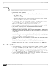
...Table 27-1 lists the access-list number and corresponding access list type and shows whether or not they are creating. If no conditions match, the switch denies the packet. The software supports these types of control. Table 27-1 Access List Numbers Access List Number 1-99 100-199 200-299 300-... extended access list IPX SAP access list Extended 48-bit MAC address access list IPX summary address access list Supported Yes Yes No No No No No No No No No No No 78-16156-01 Catalyst 3560 Switch Software Configuration Guide 27-7 The switch supports IP standard and IP extended access lists...
...Table 27-1 lists the access-list number and corresponding access list type and shows whether or not they are creating. If no conditions match, the switch denies the packet. The software supports these types of control. Table 27-1 Access List Numbers Access List Number 1-99 100-199 200-299 300-... extended access list IPX SAP access list Extended 48-bit MAC address access list IPX summary address access list Supported Yes Yes No No No No No No No No No No No 78-16156-01 Catalyst 3560 Switch Software Configuration Guide 27-7 The switch supports IP standard and IP extended access lists...
Software Configuration Guide
Page 505
...Simple Mail Transfer Protocol (SMTP) port of 25. Switch(config)# access-list 2 permit 36.48.0.3 Switch(config)# access-list 2 deny 36.48.0.0 0.0.255.255 Switch(config)# access-list 2 permit 36.0.0.0 0.255.255.255 Switch(config)# interface gigabitethernet0/1 Switch(config-if)# ip access-group 2 in from ... any 128.88.0.0 0.0.255.255 established Switch(config)# access-list 102 permit tcp any Switch(config)# interface gigabitethernet0/1 Switch(config-if)# ip access-group 102 in 78-16156-01 Catalyst 3560 Switch Software Configuration Guide 27-23 Switch(config)# access-list 102 permit tcp any...
...Simple Mail Transfer Protocol (SMTP) port of 25. Switch(config)# access-list 2 permit 36.48.0.3 Switch(config)# access-list 2 deny 36.48.0.0 0.0.255.255 Switch(config)# access-list 2 permit 36.0.0.0 0.255.255.255 Switch(config)# interface gigabitethernet0/1 Switch(config-if)# ip access-group 2 in from ... any 128.88.0.0 0.0.255.255 established Switch(config)# access-list 102 permit tcp any Switch(config)# interface gigabitethernet0/1 Switch(config-if)# ip access-group 102 in 78-16156-01 Catalyst 3560 Switch Software Configuration Guide 27-23 Switch(config)# access-list 102 permit tcp any...
Software Configuration Guide
Page 507
... logged Log Buffer (4096 bytes): 00:00:48: NTP: authentication delay calculation problems 00:09:34:%SEC-6-IPACCESSLOGS:list stan1 permitted 0.0.0.0 1 packet 00:09:59:%SEC-6-IPACCESSLOGS:list stan1 denied 10.1.1.15 1 packet 00:10:11:%SEC-6-IPACCESSLOGS:list stan1 permitted 0.0.0.0 1 packet 78-16156-01 Catalyst 3560 Switch Software Configuration Guide 27-25
... logged Log Buffer (4096 bytes): 00:00:48: NTP: authentication delay calculation problems 00:09:34:%SEC-6-IPACCESSLOGS:list stan1 permitted 0.0.0.0 1 packet 00:09:59:%SEC-6-IPACCESSLOGS:list stan1 denied 10.1.1.15 1 packet 00:10:11:%SEC-6-IPACCESSLOGS:list stan1 permitted 0.0.0.0 1 packet 78-16156-01 Catalyst 3560 Switch Software Configuration Guide 27-25

Software Configuration Guide
Page 541
... DSCP Assigned CoS CoS-to-Ingress Queue Map CoS-to-Egress Queue Map VoIP Data Traffic 46 5 5 (queue 1) VoIP Control Traffic Routing Protocol Traffic 26 48 3 6 2, 3, 4, 5, 6, 7 (queue 2) STP BPDU Traffic 56 7 3, 6, 7 (queue 2) All Other Traffic 0 0 0, 1 (queue 1) 2, 4 0, 1 (queue 3) (queue 4) Table 28-3 shows the...according to trust the QoS label received in Table 28-3 and Table 28-4. 78-16156-01 Catalyst 3560 Switch Software Configuration Guide 28-19 The switch uses the Cisco Discovery Protocol (CDP) to detect the presence or absence of the network that is globally enabled ...
... DSCP Assigned CoS CoS-to-Ingress Queue Map CoS-to-Egress Queue Map VoIP Data Traffic 46 5 5 (queue 1) VoIP Control Traffic Routing Protocol Traffic 26 48 3 6 2, 3, 4, 5, 6, 7 (queue 2) STP BPDU Traffic 56 7 3, 6, 7 (queue 2) All Other Traffic 0 0 0, 1 (queue 1) 2, 4 0, 1 (queue 3) (queue 4) Table 28-3 shows the...according to trust the QoS label received in Table 28-3 and Table 28-4. 78-16156-01 Catalyst 3560 Switch Software Configuration Guide 28-19 The switch uses the Cisco Discovery Protocol (CDP) to detect the presence or absence of the network that is globally enabled ...

Software Configuration Guide
Page 542
...(maps CoS values in incoming packets Switch(config)# mls qos map cos-dscp 0 8 16 26 32 46 to a DSCP value). 48 56 The switch automatically maps CoS values to an ... already been classified by using the auto qos voip cisco-phone or the auto qos voip trust interface configuration command, the switch automatically generates a QoS configuration based on the port... Switch(config)# mls qos srr-queue output cos-map queue 4 threshold 2 1 Switch(config)# mls qos srr-queue output cos-map queue 4 threshold 3 0 28-20 Catalyst 3560 Switch Software Configuration Guide 78-16156-01 The switch ...
...(maps CoS values in incoming packets Switch(config)# mls qos map cos-dscp 0 8 16 26 32 46 to a DSCP value). 48 56 The switch automatically maps CoS values to an ... already been classified by using the auto qos voip cisco-phone or the auto qos voip trust interface configuration command, the switch automatically generates a QoS configuration based on the port... Switch(config)# mls qos srr-queue output cos-map queue 4 threshold 2 1 Switch(config)# mls qos srr-queue output cos-map queue 4 threshold 3 0 28-20 Catalyst 3560 Switch Software Configuration Guide 78-16156-01 The switch ...

Software Configuration Guide
Page 543
...)# mls qos srr-queue output dscp-map queue 2 threshold 3 24 25 26 27 28 29 30 31 Switch(config)# mls qos srr-queue output dscp-map queue 2 threshold 3 48 49 50 51 52 53 54 55 Switch(config)# mls qos srr-queue output dscp-map queue 2 threshold 3 56 57 58 59 60 61... 46 47 The switch automatically maps DSCP values to an egress queue and to a threshold ID. Switch(config)# mls qos queue-set output 1 buffers 20 20 20 40 Switch(config-if)# srr-queue bandwidth shape 10 0 0 0 Switch(config-if)# srr-queue bandwidth share 10 10 60 20 78-16156-01 Catalyst 3560 Switch Software Configuration Guide...
...)# mls qos srr-queue output dscp-map queue 2 threshold 3 24 25 26 27 28 29 30 31 Switch(config)# mls qos srr-queue output dscp-map queue 2 threshold 3 48 49 50 51 52 53 54 55 Switch(config)# mls qos srr-queue output dscp-map queue 2 threshold 3 56 57 58 59 60 61... 46 47 The switch automatically maps DSCP values to an egress queue and to a threshold ID. Switch(config)# mls qos queue-set output 1 buffers 20 20 20 40 Switch(config-if)# srr-queue bandwidth shape 10 0 0 0 Switch(config-if)# srr-queue bandwidth share 10 10 60 20 78-16156-01 Catalyst 3560 Switch Software Configuration Guide...

Software Configuration Guide
Page 549
...is set to 0) without any policing. The default ingress and egress queue settings are described in pass-through mode (packets are switched without any rewrites and classified as best effort (the DSCP and CoS value is untrusted. Table 28-6 Default Ingress Queue Configuration Feature... queue configuration when QoS is the priority queue. The bandwidth is disabled. Threshold ID 0-39 40-47 48-63 1-1 2-1 1-1 78-16156-01 Catalyst 3560 Switch Software Configuration Guide 28-27 Chapter 28 Configuring QoS Configuring Standard QoS Default Standard QoS Configuration QoS is equally...
...is set to 0) without any policing. The default ingress and egress queue settings are described in pass-through mode (packets are switched without any rewrites and classified as best effort (the DSCP and CoS value is untrusted. Table 28-6 Default Ingress Queue Configuration Feature... queue configuration when QoS is the priority queue. The bandwidth is disabled. Threshold ID 0-39 40-47 48-63 1-1 2-1 1-1 78-16156-01 Catalyst 3560 Switch Software Configuration Guide 28-27 Chapter 28 Configuring QoS Configuring Standard QoS Default Standard QoS Configuration QoS is equally...

Software Configuration Guide
Page 550
... -DSCP map is shown in shared mode. 2. Threshold ID 0-15 16-31 32-39 40-47 48-63 2-1 3-1 4-1 1-1 4-1 Default Mapping Table Configuration The default CoS-to the same DSCP value (no markdown). 28-28 Catalyst 3560 Switch Software Configuration Guide 78-16156-01 Table 28-11 Default DSCP Output Queue Threshold Map DSCP... default IP-precedence-to the same DSCP value. The default DSCP-to queue-set when QoS is operating in Table 28-12 on page 28-48.
... -DSCP map is shown in shared mode. 2. Threshold ID 0-15 16-31 32-39 40-47 48-63 2-1 3-1 4-1 1-1 4-1 Default Mapping Table Configuration The default CoS-to the same DSCP value (no markdown). 28-28 Catalyst 3560 Switch Software Configuration Guide 78-16156-01 Table 28-11 Default DSCP Output Queue Threshold Map DSCP... default IP-precedence-to the same DSCP value. The default DSCP-to queue-set when QoS is operating in Table 28-12 on page 28-48.

Software Configuration Guide
Page 569
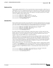
... 01 2 34 5 6 7 DSCP value 0 8 16 24 32 40 48 56 If these steps to modify the CoS-to-DSCP map. Chapter 28 Configuring QoS Configuring Standard QoS Switch(config)# interface gigabitethernet0/1 Switch(config-if)# service-policy input aggflow1 Switch(config-if)# exit Configuring DSCP Maps These sections describe how to configure...the configuration file. Configuring the CoS-to-DSCP Map You use the no mls qos cos-dscp global configuration command. 78-16156-01 Catalyst 3560 Switch Software Configuration Guide 28-47 This procedure is 0 to privileged EXEC mode. Return to 63.
... 01 2 34 5 6 7 DSCP value 0 8 16 24 32 40 48 56 If these steps to modify the CoS-to-DSCP map. Chapter 28 Configuring QoS Configuring Standard QoS Switch(config)# interface gigabitethernet0/1 Switch(config-if)# service-policy input aggflow1 Switch(config-if)# exit Configuring DSCP Maps These sections describe how to configure...the configuration file. Configuring the CoS-to-DSCP Map You use the no mls qos cos-dscp global configuration command. 78-16156-01 Catalyst 3560 Switch Software Configuration Guide 28-47 This procedure is 0 to privileged EXEC mode. Return to 63.

Software Configuration Guide
Page 570
... 3 Step 4 Step 5 end show mls qos maps ip-prec-dscp IpPrecedence-dscp map: ipprec: 0 1 2 3 4 5 6 7 dscp: 10 15 20 25 30 35 40 45 28-48 Catalyst 3560 Switch Software Configuration Guide 78-16156-01 The DSCP range is optional. Table 28-13 shows the default IP-precedence-to-DSCP map: Table 28-13... Default IP-Precedence-to-DSCP Map IP precedence value 0 1 2 34 5 6 7 DSCP value 08 16 24 32 40 48 56 If these steps to modify the IP...
... 3 Step 4 Step 5 end show mls qos maps ip-prec-dscp IpPrecedence-dscp map: ipprec: 0 1 2 3 4 5 6 7 dscp: 10 15 20 25 30 35 40 45 28-48 Catalyst 3560 Switch Software Configuration Guide 78-16156-01 The DSCP range is optional. Table 28-13 shows the default IP-precedence-to-DSCP map: Table 28-13... Default IP-Precedence-to-DSCP Map IP precedence value 0 1 2 34 5 6 7 DSCP value 08 16 24 32 40 48 56 If these steps to modify the IP...

Software Configuration Guide
Page 571
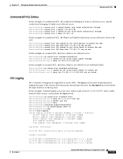
... the d1 and d2 values provides the marked-down DSCP values are shown in the body of 0. 78-16156-01 Catalyst 3560 Switch Software Configuration Guide 28-49 Step 1 Step 2 Step 3 Step 4 Step 5 Command configure terminal mls qos map ... : 30 31 32 33 34 35 36 37 38 39 4 : 40 41 42 43 44 45 46 47 48 49 5 : 00 00 00 00 00 00 00 00 58 59 6 : 60 61 62 63 Note In ... to a marked-down a DSCP value to a new value as the result of 53 corresponds to 0 Switch(config)# end Switch# show mls qos maps policed-dscp copy running-config startup-config Purpose Enter global configuration mode. For example,...
... the d1 and d2 values provides the marked-down DSCP values are shown in the body of 0. 78-16156-01 Catalyst 3560 Switch Software Configuration Guide 28-49 Step 1 Step 2 Step 3 Step 4 Step 5 Command configure terminal mls qos map ... : 30 31 32 33 34 35 36 37 38 39 4 : 40 41 42 43 44 45 46 47 48 49 5 : 00 00 00 00 00 00 00 00 58 59 6 : 60 61 62 63 Note In ... to a marked-down a DSCP value to a new value as the result of 53 corresponds to 0 Switch(config)# end Switch# show mls qos maps policed-dscp copy running-config startup-config Purpose Enter global configuration mode. For example,...
