
Installation Guide
Page 6
... and Modes 1-16 Rear-Panel Description 1-21 Power Connectors 1-22 Internal Power Supply Connector 1-23 Cisco RPS Connector 1-23 Console Port 1-24 Management Options 1-24 Network Configuration Examples 1-25 Design Concepts for Installation 2-2 Warnings 2-2 EMC Regulatory Statements 2-5 U.S.A. 2-5 Taiwan 2-5 Japan 2-6 Korea 2-6 Hungary 2-7 Installation Guidelines 2-7 Verifying Package Contents 2-8 Catalyst 3500 Series XL Hardware Installation Guide vi 78...
... and Modes 1-16 Rear-Panel Description 1-21 Power Connectors 1-22 Internal Power Supply Connector 1-23 Cisco RPS Connector 1-23 Console Port 1-24 Management Options 1-24 Network Configuration Examples 1-25 Design Concepts for Installation 2-2 Warnings 2-2 EMC Regulatory Statements 2-5 U.S.A. 2-5 Taiwan 2-5 Japan 2-6 Korea 2-6 Hungary 2-7 Installation Guidelines 2-7 Verifying Package Contents 2-8 Catalyst 3500 Series XL Hardware Installation Guide vi 78...

Installation Guide
Page 9
INDEX Grounded Equipment Warning C-23 Supply Circuit Warning C-24 No On/Off Switch Warning C-25 Power Supply Warning C-27 Work During Lightning Activity Warning C-30 Product Disposal Warning C-31 Chassis Warning-Rack-Mounting and Servicing C-33 Chassis Power Connection Warning C-38 Shock Hazard from Interconnections Warning C-41 Contents 78-6456-03 Catalyst 3500 Series XL Hardware Installation Guide ix
INDEX Grounded Equipment Warning C-23 Supply Circuit Warning C-24 No On/Off Switch Warning C-25 Power Supply Warning C-27 Work During Lightning Activity Warning C-30 Product Disposal Warning C-31 Chassis Warning-Rack-Mounting and Servicing C-33 Chassis Power Connection Warning C-38 Shock Hazard from Interconnections Warning C-41 Contents 78-6456-03 Catalyst 3500 Series XL Hardware Installation Guide ix

Installation Guide
Page 27
... Analyzer (SPAN) port monitoring on any port • Support for command switch redundancy • Support for optional Cisco 600W Redundant Power System (RPS) that operates on AC input and supplies DC output to four 1000BaseZX GBICs with the Catalyst 3508G XL switch) Management • Cisco IOS command-line interface (CLI) through the console port or Telnet •...
... Analyzer (SPAN) port monitoring on any port • Support for command switch redundancy • Support for optional Cisco 600W Redundant Power System (RPS) that operates on AC input and supplies DC output to four 1000BaseZX GBICs with the Catalyst 3508G XL switch) Management • Cisco IOS command-line interface (CLI) through the console port or Telnet •...

Installation Guide
Page 29
... of LEDs and a Mode button. (The Catalyst 3548 XL switch has a Mode label that operates on AC input and supplies DC output to the Catalyst 3524-PWR XL switch Inline Power (Catalyst 3524-PWR XL switch only) • Ability to provide inline power for Cisco IP Phones from all 24 10/100 Ethernet ports... • Auto-detection and control of inline phone power on a per-port ...
... of LEDs and a Mode button. (The Catalyst 3548 XL switch has a Mode label that operates on AC input and supplies DC output to the Catalyst 3524-PWR XL switch Inline Power (Catalyst 3524-PWR XL switch only) • Ability to provide inline power for Cisco IP Phones from all 24 10/100 Ethernet ports... • Auto-detection and control of inline phone power on a per-port ...

Installation Guide
Page 39
... operational. The label on the bottom of the power supplies in the RPS could be powered down and restarts after 15 seconds, using an RPS with a revision level lower than Z3 with a Catalyst 3508G XL or a Catalyst 3548 XL switch, the switch RPS LED might display amber (normally indicating an RPS...the LED colors and their meanings. Note The Cisco RPS 600 (model PWR600-AC-RPS) supports the Catalyst 3512, 3524, 3548, and 3508 XL switches. Note The Cisco RPS 300 (model PWR300-AC-RPS) supports the Catalyst 3524-PWR XL switch. 78-6456-04 Catalyst 3500 Series XL Hardware Installation Guide 1-15
... operational. The label on the bottom of the power supplies in the RPS could be powered down and restarts after 15 seconds, using an RPS with a revision level lower than Z3 with a Catalyst 3508G XL or a Catalyst 3548 XL switch, the switch RPS LED might display amber (normally indicating an RPS...the LED colors and their meanings. Note The Cisco RPS 600 (model PWR600-AC-RPS) supports the Catalyst 3512, 3524, 3548, and 3508 XL switches. Note The Cisco RPS 300 (model PWR300-AC-RPS) supports the Catalyst 3524-PWR XL switch. 78-6456-04 Catalyst 3500 Series XL Hardware Installation Guide 1-15

Installation Guide
Page 40
... explain how to the Cisco Redundant Power System 300 Hardware Installation Guide. Internal power supply of the power supplies in the stack. This is lost. The port modes (Table 1-6) determine the type of the port LED colors also changes. RPS is backing up another switch in the RPS could have...Port Mode LEDs Mode LED STAT UTL Port Mode Port status Switch utilization Description The port status. Front-Panel Description Chapter 1 Product Overview Table 1-5 RPS LED for the Catalyst 3524-PWR XL Switch Color Off Solid green Blinking green Solid amber Blinking amber RPS ...
... explain how to the Cisco Redundant Power System 300 Hardware Installation Guide. Internal power supply of the power supplies in the stack. This is lost. The port modes (Table 1-6) determine the type of the port LED colors also changes. RPS is backing up another switch in the RPS could have...Port Mode LEDs Mode LED STAT UTL Port Mode Port status Switch utilization Description The port status. Front-Panel Description Chapter 1 Product Overview Table 1-5 RPS LED for the Catalyst 3524-PWR XL Switch Color Off Solid green Blinking green Solid amber Blinking amber RPS ...

Installation Guide
Page 45
...-6456-04 CONSOLE DC INPUTS FOR REMOTE POWER SUPPLY SPECIFIED IN MANUAL. +5V @24A, +12V @.5A RJ-45 console port Redundant power system connector Fans Catalyst 3500 Series XL Hardware Installation Guide 1-21 Chapter 1 Product Overview Rear-Panel Description Rear-Panel Description Switch rear panels have an AC power connector, an RPS connector, and an RJ...
...-6456-04 CONSOLE DC INPUTS FOR REMOTE POWER SUPPLY SPECIFIED IN MANUAL. +5V @24A, +12V @.5A RJ-45 console port Redundant power system connector Fans Catalyst 3500 Series XL Hardware Installation Guide 1-21 Chapter 1 Product Overview Rear-Panel Description Rear-Panel Description Switch rear panels have an AC power connector, an RPS connector, and an RJ...

Installation Guide
Page 46
...~ 1.6A/0.9A 50-60HZ DC INPUTS FOR REMOTE POWER SUPPLY SPECIFIED IN MANUAL +3.3V @17A, +12 @1.1A CONSOLE AC power connector Fan exhaust RJ-45 console port Redundant power system connector Power Connectors You can provide power to the switch either through the internal power supply or through the Cisco RPS. 1-22 Catalyst 3500 Series XL Hardware Installation Guide 78-6456...
...~ 1.6A/0.9A 50-60HZ DC INPUTS FOR REMOTE POWER SUPPLY SPECIFIED IN MANUAL +3.3V @17A, +12 @1.1A CONSOLE AC power connector Fan exhaust RJ-45 console port Redundant power system connector Power Connectors You can provide power to the switch either through the internal power supply or through the Cisco RPS. 1-22 Catalyst 3500 Series XL Hardware Installation Guide 78-6456...

Installation Guide
Page 47
... Overview Rear-Panel Description Internal Power Supply Connector The internal power supply is not recommended. The power source is also connected to the Cisco Redundant Power System Hardware Installation Guide. 78-6456-04 Catalyst 3500 Series XL Hardware Installation Guide 1-23 Note Do not connect the switch power cord to an AC outlet if the switch is quasi-redundant because there...
... Overview Rear-Panel Description Internal Power Supply Connector The internal power supply is not recommended. The power source is also connected to the Cisco Redundant Power System Hardware Installation Guide. 78-6456-04 Catalyst 3500 Series XL Hardware Installation Guide 1-23 Note Do not connect the switch power cord to an AC outlet if the switch is quasi-redundant because there...

Installation Guide
Page 48
...and the supplied rollover cable and DB-9 adapter. Console Port You can order a kit (part number ACS-DSBUASYN=) containing that you want to connect the switch console port to six switches. Management Options Catalyst 3500 XL switches offer several management options: • Cisco Cluster ...web-based applications that adapter from Cisco. If more information on page B-4. For more than one switch at the same time, the subsequent switches will not be powered. You can connect a Catalyst 3500 XL switch to six switches, it can power only one switch fails at a time. For console...
...and the supplied rollover cable and DB-9 adapter. Console Port You can order a kit (part number ACS-DSBUASYN=) containing that you want to connect the switch console port to six switches. Management Options Catalyst 3500 XL switches offer several management options: • Cisco Cluster ...web-based applications that adapter from Cisco. If more information on page B-4. For more than one switch at the same time, the subsequent switches will not be powered. You can connect a Catalyst 3500 XL switch to six switches, it can power only one switch fails at a time. For console...

Installation Guide
Page 61
...Installation Warning To prevent the switch from overheating, do not operate it last. Statement 51 Warning Unplug the power cord before you work with TN power systems. Statement 19 Warning ... openings. Statement 20 78-6456-04 Catalyst 3500 Series XL Hardware Installation Guide 2-3 Statement 42 Warning This product relies on /off switch. Ensure that wiring is intended to ...be grounded. Statement 13 Warning This equipment is not overloaded. Statement 39 Warning Care must be given to connecting units to the supply ...
...Installation Warning To prevent the switch from overheating, do not operate it last. Statement 51 Warning Unplug the power cord before you work with TN power systems. Statement 19 Warning ... openings. Statement 20 78-6456-04 Catalyst 3500 Series XL Hardware Installation Guide 2-3 Statement 42 Warning This product relies on /off switch. Ensure that wiring is intended to ...be grounded. Statement 13 Warning This equipment is not overloaded. Statement 39 Warning Care must be given to connecting units to the supply ...
Installation Guide
Page 62
... Before connecting or disconnecting ground or power wires to the RPS receptacle. Statement 100 Catalyst 3500 Series XL Hardware Installation Guide 2-4 78-6456-04 For systems without a power switch, line voltages are present within the power supply when the power cord is OFF, locate the circuit...Installing and Starting Up the Switch Warning Do not touch the power supply when the power cord is removed from the DC circuit. Statement 1072 The following warning applies to the Catalyst 3508, 3512, 3524, and 3548 XL switches: Warning Attach only the Cisco RPS (model PWR600-AC...
... Before connecting or disconnecting ground or power wires to the RPS receptacle. Statement 100 Catalyst 3500 Series XL Hardware Installation Guide 2-4 78-6456-04 For systems without a power switch, line voltages are present within the power supply when the power cord is OFF, locate the circuit...Installing and Starting Up the Switch Warning Do not touch the power supply when the power cord is removed from the DC circuit. Statement 1072 The following warning applies to the Catalyst 3508, 3512, 3524, and 3548 XL switches: Warning Attach only the Cisco RPS (model PWR600-AC...
Installation Guide
Page 71
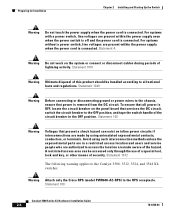
...the power cord to the left or right bracket. 78-6456-04 Catalyst 3500 Series XL Hardware Installation Guide 2-13 Chapter 2 Installing and Starting Up the Switch Installing the Switch in a Rack Mounting the Switch in a Rack After the brackets are using the Cisco RPS, see the Cisco RPS... guide to the switch. Attaching the Optional Cable Guide We recommend attaching the cable guides to the switch, use the supplied black screw, as shown in a Rack 26233 1 SYSTEM 2 3 RPS 4 5 MODE STATUS 6 7 UTIL 8 DUPLX SPEED Phillips machine screws After the switch is connected, the...
...the power cord to the left or right bracket. 78-6456-04 Catalyst 3500 Series XL Hardware Installation Guide 2-13 Chapter 2 Installing and Starting Up the Switch Installing the Switch in a Rack Mounting the Switch in a Rack After the brackets are using the Cisco RPS, see the Cisco RPS... guide to the switch. Attaching the Optional Cable Guide We recommend attaching the cable guides to the switch, use the supplied black screw, as shown in a Rack 26233 1 SYSTEM 2 3 RPS 4 5 MODE STATUS 6 7 UTIL 8 DUPLX SPEED Phillips machine screws After the switch is connected, the...
Installation Guide
Page 74
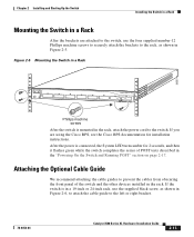
... wall stud 8 User-supplied screws 7 6 5 4 3 2 Vertical wall-mount 1 STATUS UTIL DUPLEX SPEED SYSTEM RPS MODE 30061 After the switch is attached securely to a wall stud or to the switch. If you are using the RPS, see the Cisco RPS documentation. After the power is connected, the system... shown in the "Powering On the Switch and Running POST" section on a Wall Chapter 2 Installing and Starting Up the Switch Attaching the Switch to a Wall For best support of self-tests described in Figure 2-9. Installing the Switch on page 2-17. 2-16 Catalyst 3500 Series XL Hardware...
... wall stud 8 User-supplied screws 7 6 5 4 3 2 Vertical wall-mount 1 STATUS UTIL DUPLEX SPEED SYSTEM RPS MODE 30061 After the switch is attached securely to a wall stud or to the switch. If you are using the RPS, see the Cisco RPS documentation. After the power is connected, the system... shown in the "Powering On the Switch and Running POST" section on a Wall Chapter 2 Installing and Starting Up the Switch Attaching the Switch to a Wall For best support of self-tests described in Figure 2-9. Installing the Switch on page 2-17. 2-16 Catalyst 3500 Series XL Hardware...
Installation Guide
Page 82
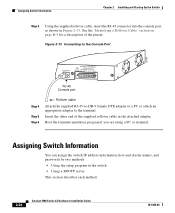
.... 2-24 Catalyst 3500 Series XL Hardware Installation Guide 78-6456-04 Insert the other end of the pinout. See the "Identifying a Rollover Cable" section on page B-5 for a description of the supplied rollover cable in the attached adapter. Figure 2-13 Connecting to the Console Port 32709 CONSOLE DC INPUTS FOR REMOTE POWER SUPPLY SPECIFIED IN...
.... 2-24 Catalyst 3500 Series XL Hardware Installation Guide 78-6456-04 Insert the other end of the pinout. See the "Identifying a Rollover Cable" section on page B-5 for a description of the supplied rollover cable in the attached adapter. Figure 2-13 Connecting to the Console Port 32709 CONSOLE DC INPUTS FOR REMOTE POWER SUPPLY SPECIFIED IN...
Installation Guide
Page 137
Appendix C Translated Safety Warnings Power Supply Warning 78-6456-04 Catalyst 3500 Series XL Hardware Installation Guide C-29
Appendix C Translated Safety Warnings Power Supply Warning 78-6456-04 Catalyst 3500 Series XL Hardware Installation Guide C-29
Installation Guide
Page 157
... 2-24 installation 2-7 to 2-17 IP address 2-24 product disposal warning C-31 PSTN 1-33 publications, related xviii Public Switched Telephone Network See PSTN Q qualified personnel warning C-7 R rack installation 2-9 bracket mounting points 2-10 rack-mounting 2-13 rear panel 1-21 to 1-22 clearance 2-8 Redundant Power Supply 78-6456-04 Catalyst 3500 Series XL Hardware Installation Guide IN-5
... 2-24 installation 2-7 to 2-17 IP address 2-24 product disposal warning C-31 PSTN 1-33 publications, related xviii Public Switched Telephone Network See PSTN Q qualified personnel warning C-7 R rack installation 2-9 bracket mounting points 2-10 rack-mounting 2-13 rear panel 1-21 to 1-22 clearance 2-8 Redundant Power Supply 78-6456-04 Catalyst 3500 Series XL Hardware Installation Guide IN-5
Installation Guide
Page 158
... Manager 1-25 supply circuit warning C-24 switch applications 1-25 startup powering on 2-17 system LED 1-14 T table-mounting 2-17 technical specifications A-1 Telnet, and accessing the CLI 1-25 temperature operating A-1 warning C-16 terminal, connecting to switch 2-23 terminal emulation software 2-23 TN power warning C-19 translated warnings C-1 troubleshooting 3-1 to 3-5 U UTL LED 1-16, 1-17 IN-6 Catalyst 3500 Series...
... Manager 1-25 supply circuit warning C-24 switch applications 1-25 startup powering on 2-17 system LED 1-14 T table-mounting 2-17 technical specifications A-1 Telnet, and accessing the CLI 1-25 temperature operating A-1 warning C-16 terminal, connecting to switch 2-23 terminal emulation software 2-23 TN power warning C-19 translated warnings C-1 troubleshooting 3-1 to 3-5 U UTL LED 1-16, 1-17 IN-6 Catalyst 3500 Series...

