
Hardware Installation Guide
Page 2
... your own expense. All rights reserved. and Aironet, ASIST, BPX, Catalyst, CCDA, CCDP, CCIE, CCNA, CCNP, Cisco, the Cisco Certified Internetwork Expert logo, Cisco IOS, the Cisco IOS logo, Cisco Press, Cisco Systems, Cisco Systems Capital, the Cisco Systems logo, Empowering the Internet Generation, Enterprise/Solver, EtherChannel, EtherSwitch, ...ARISING OUT OF THE USE OR INABILITY TO USE THIS MANUAL, EVEN IF CISCO OR ITS SUPPLIERS HAVE BEEN ADVISED OF THE POSSIBILITY OF SUCH DAMAGES. THE SPECIFICATIONS AND INFORMATION REGARDING THE PRODUCTS IN THIS MANUAL ARE SUBJECT TO CHANGE WITHOUT ...
... your own expense. All rights reserved. and Aironet, ASIST, BPX, Catalyst, CCDA, CCDP, CCIE, CCNA, CCNP, Cisco, the Cisco Certified Internetwork Expert logo, Cisco IOS, the Cisco IOS logo, Cisco Press, Cisco Systems, Cisco Systems Capital, the Cisco Systems logo, Empowering the Internet Generation, Enterprise/Solver, EtherChannel, EtherSwitch, ...ARISING OUT OF THE USE OR INABILITY TO USE THIS MANUAL, EVEN IF CISCO OR ITS SUPPLIERS HAVE BEEN ADVISED OF THE POSSIBILITY OF SUCH DAMAGES. THE SPECIFICATIONS AND INFORMATION REGARDING THE PRODUCTS IN THIS MANUAL ARE SUBJECT TO CHANGE WITHOUT ...

Hardware Installation Guide
Page 7
... 2-19 Installing the Switch on a Wall 2-20 Attaching the Brackets to the Switch 2-21 Mounting the Switch to a Wall 2-22 Powering On the Switch and Running POST 2-24 Connecting to DC Power 2-25 Preparing for Installation 2-25 Grounding the Switch 2-26 Wiring the... Go Next 2-43 Troubleshooting 3-1 Understanding POST Results 3-1 Correcting Module POST Failures 3-2 Diagnosing Problems 3-3 Technical Specifications A-1 Connectors and Cable Specifications B-1 Connector Specifications B-1 10/100 Ports B-1 100BASE-FX Ports B-2 Contents 78-6461-04 Catalyst 2900 Series XL Hardware Installation Guide vii
... 2-19 Installing the Switch on a Wall 2-20 Attaching the Brackets to the Switch 2-21 Mounting the Switch to a Wall 2-22 Powering On the Switch and Running POST 2-24 Connecting to DC Power 2-25 Preparing for Installation 2-25 Grounding the Switch 2-26 Wiring the... Go Next 2-43 Troubleshooting 3-1 Understanding POST Results 3-1 Correcting Module POST Failures 3-2 Diagnosing Problems 3-3 Technical Specifications A-1 Connectors and Cable Specifications B-1 Connector Specifications B-1 10/100 Ports B-1 100BASE-FX Ports B-2 Contents 78-6461-04 Catalyst 2900 Series XL Hardware Installation Guide vii

Hardware Installation Guide
Page 8
... Ports B-3 Console Port B-3 Cable and Adapter Specifications B-4 Crossover and Straight-Through Cable Pinouts B-4 RJ-21 Cable Pinouts B-5 Console Port B-5 Identifying a Rollover Cable B-6 Connecting to a PC B-6 Connecting to a Terminal B-7 Translated Safety Warnings C-1 Attaching the Cisco RPS (model PWR600-AC-RPS) C-1 Attaching the Cisco RPS (model PWR300-AC-RPS-N1) C-2 Qualified... C-14 Supply Circuit Warning C-15 Voltage Warning C-16 Power Supply Warning C-17 Lightning Activity Warning C-19 Product Disposal Warning C-21 Catalyst 2900 Series XL Hardware Installation Guide viii 78-6461-04
... Ports B-3 Console Port B-3 Cable and Adapter Specifications B-4 Crossover and Straight-Through Cable Pinouts B-4 RJ-21 Cable Pinouts B-5 Console Port B-5 Identifying a Rollover Cable B-6 Connecting to a PC B-6 Connecting to a Terminal B-7 Translated Safety Warnings C-1 Attaching the Cisco RPS (model PWR600-AC-RPS) C-1 Attaching the Cisco RPS (model PWR300-AC-RPS-N1) C-2 Qualified... C-14 Supply Circuit Warning C-15 Voltage Warning C-16 Power Supply Warning C-17 Lightning Activity Warning C-19 Product Disposal Warning C-21 Catalyst 2900 Series XL Hardware Installation Guide viii 78-6461-04

Hardware Installation Guide
Page 11
...on a wall. We assume that might arise when you are installing the switch. 78-6461-04 Catalyst 2900 Series XL Hardware Installation Guide xi Purpose The Catalyst 2900 Series XL Hardware Installation Guide documents the hardware features of the problems ...describes the physical and performance characteristics of the switches, explains how to identify and resolve some of Catalyst 2900 series XL switches. Chapter 3, "Troubleshooting," describes how to install a switch, and provides troubleshooting information and specifications. Preface Audience This guide is organized into the...
...on a wall. We assume that might arise when you are installing the switch. 78-6461-04 Catalyst 2900 Series XL Hardware Installation Guide xi Purpose The Catalyst 2900 Series XL Hardware Installation Guide documents the hardware features of the problems ...describes the physical and performance characteristics of the switches, explains how to identify and resolve some of Catalyst 2900 series XL switches. Chapter 3, "Troubleshooting," describes how to install a switch, and provides troubleshooting information and specifications. Preface Audience This guide is organized into the...

Hardware Installation Guide
Page 12
... Notes, cautions, and warnings use these conventions: • Commands and keywords are in boldface. • Arguments for the switches and the regulatory agency approvals. Catalyst 2900 Series XL Hardware Installation Guide xii 78-6461-04 In this situation, you enter is in boldface screen font. •... and system displays are in italic. Appendix C, "Translated Safety Warnings," provides translations in this manual. Conventions Preface Appendix A, "Technical Specifications," lists the physical and environmental specifications for which you supply values are in this guide.
... Notes, cautions, and warnings use these conventions: • Commands and keywords are in boldface. • Arguments for the switches and the regulatory agency approvals. Catalyst 2900 Series XL Hardware Installation Guide xii 78-6461-04 In this situation, you enter is in boldface screen font. •... and system displays are in italic. Appendix C, "Translated Safety Warnings," provides translations in this manual. Conventions Preface Appendix A, "Technical Specifications," lists the physical and environmental specifications for which you supply values are in this guide.

Hardware Installation Guide
Page 18
If you are using the product-specific CD and you display the document listing for doing business with Cisco. When you are connected to help customers and partners streamline business processes and improve productivity. You can obtain documentation, troubleshooting ... open access to comment on the World Wide Web, you can find information about Cisco and our networking solutions, xviii Catalyst 2900 Series XL Hardware Installation Guide 78-6461-04 Otherwise, you wish to Cisco information and resources at anytime, from the TAC website. Customers and partners can e-...
If you are using the product-specific CD and you display the document listing for doing business with Cisco. When you are connected to help customers and partners streamline business processes and improve productivity. You can obtain documentation, troubleshooting ... open access to comment on the World Wide Web, you can find information about Cisco and our networking solutions, xviii Catalyst 2900 Series XL Hardware Installation Guide 78-6461-04 Otherwise, you wish to Cisco information and resources at anytime, from the TAC website. Customers and partners can e-...
Hardware Installation Guide
Page 19
... going to your questions. To register for Cisco.com, go to the following website: http://www.cisco.com/register/ 78-6461-04 Catalyst 2900 Series XL Hardware Installation Guide xix Network functionality is degraded. In each of an order, access technical support, and view benefits specific to obtain additional personalized information and services. Contacting...
... going to your questions. To register for Cisco.com, go to the following website: http://www.cisco.com/register/ 78-6461-04 Catalyst 2900 Series XL Hardware Installation Guide xix Network functionality is degraded. In each of an order, access technical support, and view benefits specific to obtain additional personalized information and services. Contacting...

Hardware Installation Guide
Page 24
... and HP OpenView. and port-level settings. • Command-line Interface (CLI)-The switch IOS CLI software is enhanced to the Catalyst 2900 Series XL and Catalyst 3500 Series XL Software Configuration Guide. You can also display network topologies to gather link ... can configure and monitor individual switches and switch clusters by using these front-panel components. You can fully configure and monitor a standalone switch, a specific cluster member, or an entire switch cluster. Using CMS, you can fully configure and monitor the switch and switch cluster members from a remote ...
... and HP OpenView. and port-level settings. • Command-line Interface (CLI)-The switch IOS CLI software is enhanced to the Catalyst 2900 Series XL and Catalyst 3500 Series XL Software Configuration Guide. You can also display network topologies to gather link ... can configure and monitor individual switches and switch clusters by using these front-panel components. You can fully configure and monitor a standalone switch, a specific cluster member, or an entire switch cluster. Using CMS, you can fully configure and monitor the switch and switch cluster members from a remote ...

Hardware Installation Guide
Page 26
...at 10BASE-T can use a crossover cable. When connecting the switch to operate in Appendix B, "Connectors and Cable Specifications." These ports also can be connected to 328 feet (100 meters) away: • 10BASE-T-compatible devices, such as workstations, Cisco IP Phones, and hubs through standard RJ-45 connectors and ...of the attached device and advertises its own capabilities. Pinouts for Cisco IP Phones and per-port priority override. Unlike the 3524-PWR XL switch, the Catalyst 2900 XL switches do not provide inline power. Cisco IP Phones-connected to the 10/100 port-must be set ...
...at 10BASE-T can use a crossover cable. When connecting the switch to operate in Appendix B, "Connectors and Cable Specifications." These ports also can be connected to 328 feet (100 meters) away: • 10BASE-T-compatible devices, such as workstations, Cisco IP Phones, and hubs through standard RJ-45 connectors and ...of the attached device and advertises its own capabilities. Pinouts for Cisco IP Phones and per-port priority override. Unlike the 3524-PWR XL switch, the Catalyst 2900 XL switches do not provide inline power. Cisco IP Phones-connected to the 10/100 port-must be set ...

Hardware Installation Guide
Page 33
... is connected and ready to the appropriate switch documentation for redundant power system (RPS) descriptions specific for the switch. Chapter 1 Product Overview Front-Panel Description RPS LED The Catalyst 2912 LRE XL and Catalyst 2924 LRE XL switches use the Cisco RPS 600 (model PWR600-AC-RPS). Figure... 1-8 RPS LED on page 1-22. The switch goes through its normal...
... is connected and ready to the appropriate switch documentation for redundant power system (RPS) descriptions specific for the switch. Chapter 1 Product Overview Front-Panel Description RPS LED The Catalyst 2912 LRE XL and Catalyst 2924 LRE XL switches use the Cisco RPS 600 (model PWR600-AC-RPS). Figure... 1-8 RPS LED on page 1-22. The switch goes through its normal...

Hardware Installation Guide
Page 42
... (model PWR600-AC-RPS) provides a quasi-redundant power source for each external device. Cisco RPS Connector Specific Cisco RPS models support specific Catalyst 2900 XL switches: • Cisco RPS 600 (model PWR600-AC-RPS)-supports the Catalyst 2912 XL, 2924C XL, 2924 XL, 2924MF XL, and 2924M XL switches. • Cisco RPS 300 (model PWR300-AC-RPS-N1)-supports the...
... (model PWR600-AC-RPS) provides a quasi-redundant power source for each external device. Cisco RPS Connector Specific Cisco RPS models support specific Catalyst 2900 XL switches: • Cisco RPS 600 (model PWR600-AC-RPS)-supports the Catalyst 2912 XL, 2924C XL, 2924 XL, 2924MF XL, and 2924M XL switches. • Cisco RPS 300 (model PWR300-AC-RPS-N1)-supports the...

Hardware Installation Guide
Page 51
...ports is unrestricted. • Temperature around it might be easily read. - Your Catalyst 2900 XL switch is missing or damaged, contact your Cisco representative or reseller for support. Note If the switch is installed in the Related Publications, page xv. • Clearance to front and ...and check each item for damage. Rear-panel power connector is within the ranges listed in Appendix A, "Technical Specifications." • Airflow around the switch and through the vents is sufficient for unrestricted cabling. - Verifying Package Contents Note Carefully remove the contents from ...
...ports is unrestricted. • Temperature around it might be easily read. - Your Catalyst 2900 XL switch is missing or damaged, contact your Cisco representative or reseller for support. Note If the switch is installed in the Related Publications, page xv. • Clearance to front and ...and check each item for damage. Rear-panel power connector is within the ranges listed in Appendix A, "Technical Specifications." • Airflow around the switch and through the vents is sufficient for unrestricted cabling. - Verifying Package Contents Note Carefully remove the contents from ...

Hardware Installation Guide
Page 79
... you can explicitly set can reduce performance or result in the "Cable and Adapter Specifications" section on the front panel (Figure 2-28). Pinouts for configuring the 10/100...are described in no linkage. Terminal block plug Tie wrap Connecting to a 10/100 Port The switch 10/100 ports configure themselves to operate at the speed of these steps to connect to 10BASE... When connecting to workstations, servers, routers, and Cisco IP Phones, connect a straight-through Category 5 cable to an RJ-45 connector on page B-4. 78-6461-04 Catalyst 2900 Series XL Hardware Installation Guide 2-35 B ...
... you can explicitly set can reduce performance or result in the "Cable and Adapter Specifications" section on the front panel (Figure 2-28). Pinouts for configuring the 10/100...are described in no linkage. Terminal block plug Tie wrap Connecting to a 10/100 Port The switch 10/100 ports configure themselves to operate at the speed of these steps to connect to 10BASE... When connecting to workstations, servers, routers, and Cisco IP Phones, connect a straight-through Category 5 cable to an RJ-45 connector on page B-4. 78-6461-04 Catalyst 2900 Series XL Hardware Installation Guide 2-35 B ...

Hardware Installation Guide
Page 86
...parity After you have accessed the switch, you want to connect the switch console port to -DB-25 female DTE adapter if you can order a kit (part number ACS-DSBUASYN=) containing that adapter from Cisco. See the Catalyst 2900 Series XL and Catalyst 3500 Series XL Software Configuration Guide...For console port and adapter pinout information, see the "Cable and Adapter Specifications" section on page B-4. The terminal-emulation software-frequently a PC application such as Hyperterminal or Procomm Plus-makes communication between the switch and your PC- You need to provide a RJ-45-to a ...
...parity After you have accessed the switch, you want to connect the switch console port to -DB-25 female DTE adapter if you can order a kit (part number ACS-DSBUASYN=) containing that adapter from Cisco. See the Catalyst 2900 Series XL and Catalyst 3500 Series XL Software Configuration Guide...For console port and adapter pinout information, see the "Cable and Adapter Specifications" section on page B-4. The terminal-emulation software-frequently a PC application such as Hyperterminal or Procomm Plus-makes communication between the switch and your PC- You need to provide a RJ-45-to a ...

Hardware Installation Guide
Page 99
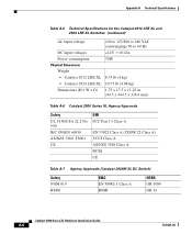
Table A-6 lists the agency approvals for additional specifications. For switches that support modules (Catalyst 2912MF XL and 2924M XL), also refer to the Catalyst 2900 Series XL Modules Installation Guide and the Catalyst 2900 Series XL ATM Modules Installation Guide for EMI and safety. 78-6461-04 Catalyst 2900 Series XL Hardware Installation Guide A-1 A A P P E N D I X Technical Specifications Table A-1, Table A-2, Table A-3, and Table A-5 list the technical specifications for the Catalyst 2900 series switches.
Table A-6 lists the agency approvals for additional specifications. For switches that support modules (Catalyst 2912MF XL and 2924M XL), also refer to the Catalyst 2900 Series XL Modules Installation Guide and the Catalyst 2900 Series XL ATM Modules Installation Guide for EMI and safety. 78-6461-04 Catalyst 2900 Series XL Hardware Installation Guide A-1 A A P P E N D I X Technical Specifications Table A-1, Table A-2, Table A-3, and Table A-5 list the technical specifications for the Catalyst 2900 series switches.
Hardware Installation Guide
Page 100
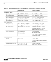
Appendix A Technical Specifications Table A-1 Technical Specifications for the Catalyst 2912 XL and Catalyst 2912MF XL Switches Environmental Ranges Operating temperature Storage temperature Operating humidity Operating altitude Storage altitude Power Requirements AC input voltage DC input voltages Catalyst 2912 XL 32 to 113°F (0 to 45°C) -4 ...(maximum) 239 Btus per hour 7 lb (3.2 kg) Dimensions (H x W x D) 1.73 x 17.5 x 9.79 in. (4.4 x 44.5 x 24.8 cm) Catalyst 2912MF XL 32 to 113°F (0 to 45°C) -4 to 149°F (-10 to 65°C) 10 to 85% (noncondensing) Up to 10,000 ft...
Appendix A Technical Specifications Table A-1 Technical Specifications for the Catalyst 2912 XL and Catalyst 2912MF XL Switches Environmental Ranges Operating temperature Storage temperature Operating humidity Operating altitude Storage altitude Power Requirements AC input voltage DC input voltages Catalyst 2912 XL 32 to 113°F (0 to 45°C) -4 ...(maximum) 239 Btus per hour 7 lb (3.2 kg) Dimensions (H x W x D) 1.73 x 17.5 x 9.79 in. (4.4 x 44.5 x 24.8 cm) Catalyst 2912MF XL 32 to 113°F (0 to 45°C) -4 to 149°F (-10 to 65°C) 10 to 85% (noncondensing) Up to 10,000 ft...

Hardware Installation Guide
Page 101
... (3.2 kg) 1.73 x 17.5 x 9.79 in . (4.4 x 44.5 x 24.8 cm) Optical transmitter - nm = nanometers 2. Appendix A Technical Specifications Table A-2 Technical Specifications for the Catalyst 2924 XL and Catalyst 2924C XL Switches Catalyst 2924 XL Environmental Operating Ranges Operating temperature 32 to 113°F (0 to 45°C) Storage temperature -4 to 149°F (-10 to...input voltage DC input voltages 100 to 127/200 to 240 VAC (autoranging) 50 to -14 dBm 78-6461-04 Catalyst 2900 Series XL Hardware Installation Guide A-3 receiver Optical power transmitter - Transmit - 1.
... (3.2 kg) 1.73 x 17.5 x 9.79 in . (4.4 x 44.5 x 24.8 cm) Optical transmitter - nm = nanometers 2. Appendix A Technical Specifications Table A-2 Technical Specifications for the Catalyst 2924 XL and Catalyst 2924C XL Switches Catalyst 2924 XL Environmental Operating Ranges Operating temperature 32 to 113°F (0 to 45°C) Storage temperature -4 to 149°F (-10 to...input voltage DC input voltages 100 to 127/200 to 240 VAC (autoranging) 50 to -14 dBm 78-6461-04 Catalyst 2900 Series XL Hardware Installation Guide A-3 receiver Optical power transmitter - Transmit - 1.
Hardware Installation Guide
Page 102
Appendix A Technical Specifications Table A-3 Technical Specifications for the Catalyst 2924M XL Switches Environmental Operating Ranges Operating temperature 32 to 113°F (0 to 45°C) Storage temperature -4 to 149°F (-10 to 65°C) Operating humidity 10 to ... Btus per hour Physical Dimensions Weight 13.5 lb (6.12 kg) 15 lb (6.8 kg) with two modules installed Dimensions (H x W x D) 3.46 x 17.5 x 12 in. (8.8 x 44.5 x 30.5 cm) Catalyst 2900 Series XL Hardware Installation Guide A-4 78-6461-04
Appendix A Technical Specifications Table A-3 Technical Specifications for the Catalyst 2924M XL Switches Environmental Operating Ranges Operating temperature 32 to 113°F (0 to 45°C) Storage temperature -4 to 149°F (-10 to 65°C) Operating humidity 10 to ... Btus per hour Physical Dimensions Weight 13.5 lb (6.12 kg) 15 lb (6.8 kg) with two modules installed Dimensions (H x W x D) 3.46 x 17.5 x 12 in. (8.8 x 44.5 x 30.5 cm) Catalyst 2900 Series XL Hardware Installation Guide A-4 78-6461-04
Hardware Installation Guide
Page 103
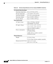
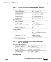
...,000 ft (3000 m) Up to 15,000 ft (4570 m) 100W -36 to 15,000 ft (4570 m) Catalyst 2900 Series XL Hardware Installation Guide A-5 Appendix A Technical Specifications 78-6461-04 Table A-4 Technical Specifications for Catalyst 2924M XL DC Switches Environmental Ranges Operating temperature Storage temperature Operating humidity Operating altitude Storage altitude Power Requirements Power consumption DC...
...,000 ft (3000 m) Up to 15,000 ft (4570 m) 100W -36 to 15,000 ft (4570 m) Catalyst 2900 Series XL Hardware Installation Guide A-5 Appendix A Technical Specifications 78-6461-04 Table A-4 Technical Specifications for Catalyst 2924M XL DC Switches Environmental Ranges Operating temperature Storage temperature Operating humidity Operating altitude Storage altitude Power Requirements Power consumption DC...
Hardware Installation Guide
Page 104
... A Technical Specifications Table A-5 Technical Specifications for the Catalyst 2912 LRE XL and 2924 LRE XL Switches (continued) AC input voltage 100 to 127/200 to 240 VAC (autoranging) 50 to 60 Hz DC input voltages +12V @12A Power consumption 70W Physical Dimensions Weight • Catalyst 2912 LRE XL 8.75 lb (4 kg) • Catalyst 2924 LRE XL..., TS001 CE EMI FCC Part 15 Class A EN 55022 Class A (CISPR 22 Class A) VCCI Class A AS/NZS 3548 Class A BCIQ CE Table A-7 Agency Approvals (Catalyst 2924M XL DC Switch) Safety NOM 019 BSMI EMC EN 50082-1 Class A BSMI NEBS GR-1089 GR-63...
... A Technical Specifications Table A-5 Technical Specifications for the Catalyst 2912 LRE XL and 2924 LRE XL Switches (continued) AC input voltage 100 to 127/200 to 240 VAC (autoranging) 50 to 60 Hz DC input voltages +12V @12A Power consumption 70W Physical Dimensions Weight • Catalyst 2912 LRE XL 8.75 lb (4 kg) • Catalyst 2924 LRE XL..., TS001 CE EMI FCC Part 15 Class A EN 55022 Class A (CISPR 22 Class A) VCCI Class A AS/NZS 3548 Class A BCIQ CE Table A-7 Agency Approvals (Catalyst 2924M XL DC Switch) Safety NOM 019 BSMI EMC EN 50082-1 Class A BSMI NEBS GR-1089 GR-63...