
Hardware Installation Guide
Page 5
...-X GBIC Module Ports 2-35 Connecting to 1000BASE-T GBIC Module Ports 2-36 Connecting to GigaStack GBIC Module Ports 2-37 Connecting to SFP Modules 2-38 Connecting to Fiber-Optic SFP Modules 2-38 Connecting to 1000BASE-T SFP Modules 2-39 Where to Go Next 2-40 Troubleshooting 3-1 Understanding POST Results 3-1 Diagnosing Problems 3-1 Technical Specifications A-1 Connectors and... Cable Pinouts for 10/100 Ports B-7 Four Twisted-Pair Cable Pinouts for 1000BASE-T Ports B-8 RJ-21 Cable Pinouts B-8 Adapter Pinouts B-10 Contents OL-6156-01 Catalyst 2950 Switch Hardware Installation Guide v
...-X GBIC Module Ports 2-35 Connecting to 1000BASE-T GBIC Module Ports 2-36 Connecting to GigaStack GBIC Module Ports 2-37 Connecting to SFP Modules 2-38 Connecting to Fiber-Optic SFP Modules 2-38 Connecting to 1000BASE-T SFP Modules 2-39 Where to Go Next 2-40 Troubleshooting 3-1 Understanding POST Results 3-1 Diagnosing Problems 3-1 Technical Specifications A-1 Connectors and... Cable Pinouts for 10/100 Ports B-7 Four Twisted-Pair Cable Pinouts for 1000BASE-T Ports B-8 RJ-21 Cable Pinouts B-8 Adapter Pinouts B-10 Contents OL-6156-01 Catalyst 2950 Switch Hardware Installation Guide v

Hardware Installation Guide
Page 22
...) Coarse Wave Division Multiplexer (CWDM) fiber-optic GBIC GigaStack GBIC • Configuration - For 10/100/1000 ports on the Catalyst 2950T-48-SI and 2950 LRE switches, autonegotiates the speed and duplex setting when operating at 1000 Mbps, it supports only full-duplex mode. - Supports 8192 MAC addresses - Catalyst 2950SX-24 switch-24 10/100 Ethernet ports and...
...) Coarse Wave Division Multiplexer (CWDM) fiber-optic GBIC GigaStack GBIC • Configuration - For 10/100/1000 ports on the Catalyst 2950T-48-SI and 2950 LRE switches, autonegotiates the speed and duplex setting when operating at 1000 Mbps, it supports only full-duplex mode. - Supports 8192 MAC addresses - Catalyst 2950SX-24 switch-24 10/100 Ethernet ports and...
Hardware Installation Guide
Page 29
... CPE devices. You can use only the copper or the fiber-optic port at 1000 Mbps in Table 2-1 to order the patch cables that you can connect the Cisco 576 LRE CPE 997 device only to LRE ports on a Catalyst 2950ST-24 LRE 997 switch. You can hot swap the CPE devices without powering down...
... CPE devices. You can use only the copper or the fiber-optic port at 1000 Mbps in Table 2-1 to order the patch cables that you can connect the Cisco 576 LRE CPE 997 device only to LRE ports on a Catalyst 2950ST-24 LRE 997 switch. You can hot swap the CPE devices without powering down...

Hardware Installation Guide
Page 30
...the security code and CRC. When a GBIC module is required to connect directly to nine supported switches. Note If you use a POTS splitter with the Catalyst 2950 LRE switches and Cisco LRE CPE, see the Cisco LRE CPE Hardware Installation Guide. If a connection to a telephone network is not required, a...). • 1000BASE-T GBIC module for copper connections that cannot exceed 328 feet (100 meters). • CWDM GBIC module for single-mode fiber-optic connections that contains the module serial number, the vendor name and ID, a unique security code, and cyclic redundancy check (CRC). If...
...the security code and CRC. When a GBIC module is required to connect directly to nine supported switches. Note If you use a POTS splitter with the Catalyst 2950 LRE switches and Cisco LRE CPE, see the Cisco LRE CPE Hardware Installation Guide. If a connection to a telephone network is not required, a...). • 1000BASE-T GBIC module for copper connections that cannot exceed 328 feet (100 meters). • CWDM GBIC module for single-mode fiber-optic connections that contains the module serial number, the vendor name and ID, a unique security code, and cyclic redundancy check (CRC). If...

Hardware Installation Guide
Page 31
...front of a copper 10/100/1000 port and a fiber-optic SFP module slot. When determining where to place the switch, be connecting to both, in the Catalyst 2950 LRE switch release notes. Within each port, you can configure the Catalyst 2950 LRE switch so that the SFP module port does not take ...precedence over the 10/100/1000 port. If you can connect to fiber-optic SFP modules. See the Catalyst 2950 LRE switch release notes for reliable communications, the cable must not exceed the stipulated cable length. Each port must match the wave...
...front of a copper 10/100/1000 port and a fiber-optic SFP module slot. When determining where to place the switch, be connecting to both, in the Catalyst 2950 LRE switch release notes. Within each port, you can configure the Catalyst 2950 LRE switch so that the SFP module port does not take ...precedence over the 10/100/1000 port. If you can connect to fiber-optic SFP modules. See the Catalyst 2950 LRE switch release notes for reliable communications, the cable must not exceed the stipulated cable length. Each port must match the wave...

Hardware Installation Guide
Page 32
... you must also install a mode-conditioning patch cord between the fiber-optic cable plant and the receiving port on the Catalyst 2950 LRE switch. The mode-conditioning patch cord is invalid, the switch places the interface in the switch, the switch software reads the EEPROM to 100 km)2 1. If the serial... the connectors. Using an ordinary patch cord with 62.5-micron diameter MMF, you are using dispersion-shifted SMF or low-attenuation SMF; Note Cisco-approved SFP modules have a serial EEPROM that contains the module serial number, the vendor name and ID, a unique security code, and ...
... you must also install a mode-conditioning patch cord between the fiber-optic cable plant and the receiving port on the Catalyst 2950 LRE switch. The mode-conditioning patch cord is invalid, the switch places the interface in the switch, the switch software reads the EEPROM to 100 km)2 1. If the serial... the connectors. Using an ordinary patch cord with 62.5-micron diameter MMF, you are using dispersion-shifted SMF or low-attenuation SMF; Note Cisco-approved SFP modules have a serial EEPROM that contains the module serial number, the vendor name and ID, a unique security code, and ...
Hardware Installation Guide
Page 39
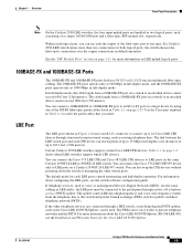
... of the total bandwidth, and so on. Figure 1-20 to Figure 1-24 show the bandwidth utilization percentages displayed by default, the switch chooses the fiber-optic connection over the copper connection. If an LRE switch senses connections to the 10/100/1000 port, depending on which is using...Port is operating at 10 Mbps. If all LEDs on a Catalyst 2950-12, 2950-24, 2950C-24, 2950SX-24, or 2950T-24 switch are green (no amber showing), the switch is operating at 100 Mbps. On an LRE switch, the LEDs for the LRE Switches (continued) Port Mode SPEED Color Meaning 10/100/1000 ports1...
... of the total bandwidth, and so on. Figure 1-20 to Figure 1-24 show the bandwidth utilization percentages displayed by default, the switch chooses the fiber-optic connection over the copper connection. If an LRE switch senses connections to the 10/100/1000 port, depending on which is using...Port is operating at 10 Mbps. If all LEDs on a Catalyst 2950-12, 2950-24, 2950C-24, 2950SX-24, or 2950T-24 switch are green (no amber showing), the switch is operating at 100 Mbps. On an LRE switch, the LEDs for the LRE Switches (continued) Port Mode SPEED Color Meaning 10/100/1000 ports1...

Hardware Installation Guide
Page 49
... service this unit, contact your reseller or Cisco sales representative. Statement 121D OL-6156-01 Catalyst 2950 Switch Hardware Installation Guide 2-3 Statement 48 Warning To comply with optical instruments. Statement 1051 Warning The Catalyst 2950G-24-EI-DC contains no field-replaceable units (FRUs...connected to be emitted from disconnected fibers or connectors. Do not stare into beams or view directly with safety regulations, mount switches on any other equipment. Metal objects will heat up . Statement 121C Warning The Catalyst 2950ST-24 LRE 997 contains no field-...
... service this unit, contact your reseller or Cisco sales representative. Statement 121D OL-6156-01 Catalyst 2950 Switch Hardware Installation Guide 2-3 Statement 48 Warning To comply with optical instruments. Statement 1051 Warning The Catalyst 2950G-24-EI-DC contains no field-replaceable units (FRUs...connected to be emitted from disconnected fibers or connectors. Do not stare into beams or view directly with safety regulations, mount switches on any other equipment. Metal objects will heat up . Statement 121C Warning The Catalyst 2950ST-24 LRE 997 contains no field-...
Hardware Installation Guide
Page 69
... do not install or remove the SFP module with security information. Use only Cisco SFP modules on installing, removing, and cabling the SFP module, refer to identify and validate that the Catalyst 2950 LRE switch supports. Each SFP module has an internal serial EEPROM that is absolutely necessary....modules provide the uplink interfaces. Do not remove and insert SFP modules more often than is encoded with fiber-optic cables attached to it because of the cable, and for Cisco to your SFP module uses before removing or installing an SFP module. Chapter 2 Installation Installing and ...
... do not install or remove the SFP module with security information. Use only Cisco SFP modules on installing, removing, and cabling the SFP module, refer to identify and validate that the Catalyst 2950 LRE switch supports. Each SFP module has an internal serial EEPROM that is absolutely necessary....modules provide the uplink interfaces. Do not remove and insert SFP modules more often than is encoded with fiber-optic cables attached to it because of the cable, and for Cisco to your SFP module uses before removing or installing an SFP module. Chapter 2 Installation Installing and ...

Hardware Installation Guide
Page 71
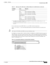
...modules, insert the RJ-45 cable connector into the optical ports of the SFP module to use . Step 3 Step 4 For fiber-optic SFP modules, insert a dust plug into the SFP module. Unlock and remove the SFP module, as shown in a parallel...Catalyst 2950 Switch Hardware Installation Guide 2-25 Tip For reattachment, note which cable connector plug is send (TX) and which is receive (RX). Chapter 2 Installation Installing and Removing SFP Modules Figure 2-31 Installing an SFP Module into an SFP Module Slot 19 20 21 22 23 24 Catalyst 2950 LRE SERIES 1 2 1 2 81564 Step 5 For fiber...
...modules, insert the RJ-45 cable connector into the optical ports of the SFP module to use . Step 3 Step 4 For fiber-optic SFP modules, insert a dust plug into the SFP module. Unlock and remove the SFP module, as shown in a parallel...Catalyst 2950 Switch Hardware Installation Guide 2-25 Tip For reattachment, note which cable connector plug is send (TX) and which is receive (RX). Chapter 2 Installation Installing and Removing SFP Modules Figure 2-31 Installing an SFP Module into an SFP Module Slot 19 20 21 22 23 24 Catalyst 2950 LRE SERIES 1 2 1 2 81564 Step 5 For fiber...
Hardware Installation Guide
Page 73
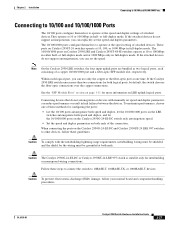
.... When connecting the ports on LRE uplink logical ports. These ports on both ends of attached devices. Caution The Catalyst 2950G-24-EI-DC or Catalyst 2950ST-24 LRE 997 switch is suitable only for configuring the ports: • Let the 10/100 ports autonegotiate both speed and duplex, let...10 or 100 Mbps in either half- Within each consisting of attached devices.They operate at both logical ports, by default, the switch chooses the fiber-optic connections over the copper connections. or full-duplex mode. Chapter 2 Installation Connecting to 10/100 and 10/100/1000 Ports...
.... When connecting the ports on LRE uplink logical ports. These ports on both ends of attached devices. Caution The Catalyst 2950G-24-EI-DC or Catalyst 2950ST-24 LRE 997 switch is suitable only for configuring the ports: • Let the 10/100 ports autonegotiate both speed and duplex, let...10 or 100 Mbps in either half- Within each consisting of attached devices.They operate at both logical ports, by default, the switch chooses the fiber-optic connections over the copper connections. or full-duplex mode. Chapter 2 Installation Connecting to 10/100 and 10/100/1000 Ports...

Hardware Installation Guide
Page 75
...-to-SC multimode cable 1-meter, MT-RJ-to-ST multimode cable 3-meter, MT-RJ-to-ST multimode cable 5-meter, MT-RJ-to-ST multimode cable Cisco Part Number CAB-MTRJ-SC-MM-1M CAB-MTRJ-SC-MM-3M CAB-MTRJ-SC-MM-5M CAB-MTRJ-ST-MM-1M CAB-MTRJ-ST... the fiber-optic cable until you need. Chapter 2 Installation Connecting to 100BASE-FX and 1000BASE-SX Ports Connecting to connect the cable. Table 2-1 MT-RJ Patch Cables for future use. Follow these steps to connect the switch to an SC or ST port on the target device. OL-6156-01 Catalyst 2950 Switch Hardware...
...-to-SC multimode cable 1-meter, MT-RJ-to-ST multimode cable 3-meter, MT-RJ-to-ST multimode cable 5-meter, MT-RJ-to-ST multimode cable Cisco Part Number CAB-MTRJ-SC-MM-1M CAB-MTRJ-SC-MM-3M CAB-MTRJ-SC-MM-5M CAB-MTRJ-ST-MM-1M CAB-MTRJ-ST... the fiber-optic cable until you need. Chapter 2 Installation Connecting to 100BASE-FX and 1000BASE-SX Ports Connecting to connect the cable. Table 2-1 MT-RJ Patch Cables for future use. Follow these steps to connect the switch to an SC or ST port on the target device. OL-6156-01 Catalyst 2950 Switch Hardware...

Hardware Installation Guide
Page 81
...requirements, intrabuilding wiring must be shielded, and the shield for intrabuilding or nonexposed wiring connections. Caution The Catalyst 2950G-24-EI-DC or Catalyst 2950ST-24 LRE 997 switch is suitable only for the wiring must be grounded at both ends. For detailed instructions about how ... Remove the rubber plugs from the GBIC module port, and store them for future use. After installing the 1000BASE-X GBIC in the fiber-optic receptacle (see Figure 2-40). Chapter 2 Installation Connecting to GBIC Module Ports Connecting to GBIC Module Ports These sections describe how ...
...requirements, intrabuilding wiring must be shielded, and the shield for intrabuilding or nonexposed wiring connections. Caution The Catalyst 2950G-24-EI-DC or Catalyst 2950ST-24 LRE 997 switch is suitable only for the wiring must be grounded at both ends. For detailed instructions about how ... Remove the rubber plugs from the GBIC module port, and store them for future use. After installing the 1000BASE-X GBIC in the fiber-optic receptacle (see Figure 2-40). Chapter 2 Installation Connecting to GBIC Module Ports Connecting to GBIC Module Ports These sections describe how ...

Hardware Installation Guide
Page 82
... device. Connecting to GBIC Module Ports Figure 2-40 Connecting to a 1000 BASE-X GBIC Port 1 Catalyst 2950 SERIES 2 Chapter 2 Installation 65296 Step 3 Step 4 Step 5 Insert the other cable end in a fiber-optic receptacle on , there might be a cable problem, or there might be sure to use... a four twisted-pair, Category 5 cable. 2-36 Catalyst 2950 Switch Hardware Installation Guide OL-6156-01 Note When connecting to a 1000BASE-T device,...
... device. Connecting to GBIC Module Ports Figure 2-40 Connecting to a 1000 BASE-X GBIC Port 1 Catalyst 2950 SERIES 2 Chapter 2 Installation 65296 Step 3 Step 4 Step 5 Insert the other cable end in a fiber-optic receptacle on , there might be a cable problem, or there might be sure to use... a four twisted-pair, Category 5 cable. 2-36 Catalyst 2950 Switch Hardware Installation Guide OL-6156-01 Note When connecting to a 1000BASE-T device,...

Hardware Installation Guide
Page 84
...For instructions on page 2-4 and in the target device. The plugs and caps protect the SFP module ports and cables from the module port and fiber-optic cable, and store them for information about how to the SFP module, be a problem with the adapter installed in the "SFP Module ... section on page 1-11. This process takes about 30 seconds, and then the port LED turns green. 2-38 Catalyst 2950 Switch Hardware Installation Guide OL-6156-01 The LED turns green when the switch and the target device have an established link. Step 1 Step 2 Step 3 Step 4 Remove the rubber plugs ...
...For instructions on page 2-4 and in the target device. The plugs and caps protect the SFP module ports and cables from the module port and fiber-optic cable, and store them for information about how to the SFP module, be a problem with the adapter installed in the "SFP Module ... section on page 1-11. This process takes about 30 seconds, and then the port LED turns green. 2-38 Catalyst 2950 Switch Hardware Installation Guide OL-6156-01 The LED turns green when the switch and the target device have an established link. Step 1 Step 2 Step 3 Step 4 Remove the rubber plugs ...

Hardware Installation Guide
Page 85
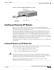
...cable. Observe the port status LED. Figure 2-44 Connecting to a Fiber-Optic SFP Module Port 81568 19 20 21 22 23 24 Cable Catalyst 2950 SERIES LRE 1 2 1 2 Step 5 If necessary, reconfigure and restart the switch or target device. Connecting to 1000BASE-T SFP Modules Follow these steps to... connect a Category 5 cable to switches or repeaters, insert a four twisted-pair, crossover cable. See Chapter 3, "Troubleshooting," for solutions to cabling problems. Figure 2-43 Connecting to a 1000BASE-T SFP Module 19 20 21 22 23 24 Catalyst 2950 SERIES LRE 1 2 1 2 97631 RJ-...
...cable. Observe the port status LED. Figure 2-44 Connecting to a Fiber-Optic SFP Module Port 81568 19 20 21 22 23 24 Cable Catalyst 2950 SERIES LRE 1 2 1 2 Step 5 If necessary, reconfigure and restart the switch or target device. Connecting to 1000BASE-T SFP Modules Follow these steps to... connect a Category 5 cable to switches or repeaters, insert a four twisted-pair, crossover cable. See Chapter 3, "Troubleshooting," for solutions to cabling problems. Figure 2-43 Connecting to a 1000BASE-T SFP Module 19 20 21 22 23 24 Catalyst 2950 SERIES LRE 1 2 1 2 97631 RJ-...

Hardware Installation Guide
Page 91
Table A-6 lists the technical specifications for the Catalyst 2950G-24-EI-DC switch. Table A-1 Technical Specifications for Catalyst 2950-12, 2950-24, 2950C-24, 2950SX-24, and 2950T-24 Switches Environmental Ranges Operating temperature 32 to 113°F (0 to 45°C) ...fiber-optic uplink ports. per sec (2.13 m per sec)1 AC input voltage DC input voltages for the Cisco RPS2 300 Redundant Power System 100 to 127/200 to 240 VAC (autoranging) 50 to 15,000 ft (4570 m) 84 in . (4.36 x 44.45 x 24.18 cm) 1. This switch meets ASTM D3332. 2. RPS = redundant power system Catalyst...
Table A-6 lists the technical specifications for the Catalyst 2950G-24-EI-DC switch. Table A-1 Technical Specifications for Catalyst 2950-12, 2950-24, 2950C-24, 2950SX-24, and 2950T-24 Switches Environmental Ranges Operating temperature 32 to 113°F (0 to 45°C) ...fiber-optic uplink ports. per sec (2.13 m per sec)1 AC input voltage DC input voltages for the Cisco RPS2 300 Redundant Power System 100 to 127/200 to 240 VAC (autoranging) 50 to 15,000 ft (4570 m) 84 in . (4.36 x 44.45 x 24.18 cm) 1. This switch meets ASTM D3332. 2. RPS = redundant power system Catalyst...
Hardware Installation Guide
Page 95
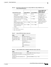
SFP = small form-factor pluggable 3. Appendix A Technical Specifications Table A-6 Fiber-Optic Port Specifications for Catalyst 2950C-24, Catalyst 2950SX-24, and Catalyst 2950 LRE Switches Fiber-Port Power Levels Catalyst 2950C-24 Optical transmitter wavelength 1300 nm1 Optical receiver sensitivity -33.5 to for 50/125-micron cabling -11.8 dBm3 Optical receiver sensitivity -33.5 to for 62.5/125-...
SFP = small form-factor pluggable 3. Appendix A Technical Specifications Table A-6 Fiber-Optic Port Specifications for Catalyst 2950C-24, Catalyst 2950SX-24, and Catalyst 2950 LRE Switches Fiber-Port Power Levels Catalyst 2950C-24 Optical transmitter wavelength 1300 nm1 Optical receiver sensitivity -33.5 to for 50/125-micron cabling -11.8 dBm3 Optical receiver sensitivity -33.5 to for 62.5/125-...
Hardware Installation Guide
Page 100
... at one port is designated with an X or when both logical ports, the switch chooses the fiber-optic connections over the copper connections in default operation. If the Catalyst 2950 LRE switch senses more than two connections for more information on LRE uplink logical ports. Figure ...on page 1-11 for both ports do not have an X. See the "SFP Module Slots" section on Catalyst 2950T-24, Catalyst 2950T-48-SI, and Catalyst 2950 Long-Reach Ethernet (LRE) switches use a two or four twisted-pair, crossover cable. Connector Specifications Appendix B Connectors and Cables Note Use ...
... at one port is designated with an X or when both logical ports, the switch chooses the fiber-optic connections over the copper connections in default operation. If the Catalyst 2950 LRE switch senses more than two connections for more information on LRE uplink logical ports. Figure ...on page 1-11 for both ports do not have an X. See the "SFP Module Slots" section on Catalyst 2950T-24, Catalyst 2950T-48-SI, and Catalyst 2950 Long-Reach Ethernet (LRE) switches use a two or four twisted-pair, crossover cable. Connector Specifications Appendix B Connectors and Cables Note Use ...

Hardware Installation Guide
Page 102
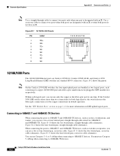
or 62.5/125-micron multimode fiber-optic cabling. You can connect a 100BASE-FX or 1000BASE-SX port to order the patch cables that you need. Figure B-4 MT-RJ Connector 28845 1000BASE-X ... of the MT-RJ fiber-optic patch cables listed in Figure B-5. Use the Cisco part numbers in Figure B-2. Figure B-5 1000BASE-X SC Connector 60535 Tx Rx 1000BASE-T GBIC Module Ports The 1000BASE-T GBIC module port uses one RJ-45 connector, as shown in Figure B-4. Figure B-6 GigaStack Connector 60536 Catalyst 2950 Switch Hardware Installation Guide B-4 OL...
or 62.5/125-micron multimode fiber-optic cabling. You can connect a 100BASE-FX or 1000BASE-SX port to order the patch cables that you need. Figure B-4 MT-RJ Connector 28845 1000BASE-X ... of the MT-RJ fiber-optic patch cables listed in Figure B-5. Use the Cisco part numbers in Figure B-2. Figure B-5 1000BASE-X SC Connector 60535 Tx Rx 1000BASE-T GBIC Module Ports The 1000BASE-T GBIC module port uses one RJ-45 connector, as shown in Figure B-4. Figure B-6 GigaStack Connector 60536 Catalyst 2950 Switch Hardware Installation Guide B-4 OL...

