Configuration Guide
Page 33
... home or office to the Internet or an intranet at least two queues per port to prioritize voice and data traffic as the Catalyst 3550-12G switch. Using the required Cisco proprietary signaling and cabling, the GigaStack GBIC-to create a GigaStack loopback, and ...The GigaStack GBIC supports one of Catalyst 2950-48 switches, you use Gigabit modules to connect the switches directly to a backbone switch in a stack configuration) to other can create backup paths between the switches and network resources. 78-11380-03 Catalyst 2950 Desktop Switch Software Configuration Guide 1-9 A ...
... home or office to the Internet or an intranet at least two queues per port to prioritize voice and data traffic as the Catalyst 3550-12G switch. Using the required Cisco proprietary signaling and cabling, the GigaStack GBIC-to create a GigaStack loopback, and ...The GigaStack GBIC supports one of Catalyst 2950-48 switches, you use Gigabit modules to connect the switches directly to a backbone switch in a stack configuration) to other can create backup paths between the switches and network resources. 78-11380-03 Catalyst 2950 Desktop Switch Software Configuration Guide 1-9 A ...
Configuration Guide
Page 36
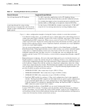
... inter-VLAN routing and allows the router to focus on the Catalyst 3524-PWR XL switches provides -48 VDC power to create a Gigabit backbone. Using CMS and Cisco switch clustering technology, you can have up to the 10/100 ports on the Catalyst 2950 switches. These multiservice switch ports automatically detect if an IP phone is connected to the same...
... inter-VLAN routing and allows the router to focus on the Catalyst 3524-PWR XL switches provides -48 VDC power to create a Gigabit backbone. Using CMS and Cisco switch clustering technology, you can have up to the 10/100 ports on the Catalyst 2950 switches. These multiservice switch ports automatically detect if an IP phone is connected to the same...
Configuration Guide
Page 172
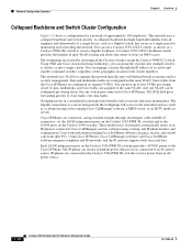
...-12 64 Catalyst 2950-24 64 Catalyst 2950C-24 250 Catalyst 2950G-12-EI 250 Catalyst 2950G-24-EI 250 Catalyst 2950G-48-EI 250 Catalyst 2950G-24-EI-DC 250 Catalyst 2950T-24 250 The Catalyst 2950 switches support IEEE 802.1Q trunking methods for transmitting VLAN traffic over 100BASE-T and Gigabit Ethernet ports. For more than one VLAN in the stack, be sure...
...-12 64 Catalyst 2950-24 64 Catalyst 2950C-24 250 Catalyst 2950G-12-EI 250 Catalyst 2950G-24-EI 250 Catalyst 2950G-48-EI 250 Catalyst 2950G-24-EI-DC 250 Catalyst 2950T-24 250 The Catalyst 2950 switches support IEEE 802.1Q trunking methods for transmitting VLAN traffic over 100BASE-T and Gigabit Ethernet ports. For more than one VLAN in the stack, be sure...

Configuration Guide
Page 277
...48-bit MAC address. The value is received; mvr mode {dynamic | compatible} (Optional) Specify the MVR mode of IP addresses. show mvr show mvr members Verify the configuration. mvr vlan vlan-id (Optional) Specify the VLAN in which multicast data is in the configuration file. 78-11380-03 Catalyst 2950 Desktop Switch... or one television channel. The default is 1 to wait for compatibility with Catalyst 2900 XL and Catalyst 3500 XL switches and does not support IGMP dynamic joins on source ports. Any multicast data sent to receive data on that multicast address. mvr querytime...
...48-bit MAC address. The value is received; mvr mode {dynamic | compatible} (Optional) Specify the MVR mode of IP addresses. show mvr show mvr members Verify the configuration. mvr vlan vlan-id (Optional) Specify the VLAN in which multicast data is in the configuration file. 78-11380-03 Catalyst 2950 Desktop Switch... or one television channel. The default is 1 to wait for compatibility with Catalyst 2900 XL and Catalyst 3500 XL switches and does not support IGMP dynamic joins on source ports. Any multicast data sent to receive data on that multicast address. mvr querytime...

Configuration Guide
Page 286
... will consume bandwidth on the IP subnet to be specified.) You can specify a UDP source, destination port number, or both at the same time.) 12-4 Catalyst 2950 Desktop Switch Software Configuration Guide 78-11380-03 Understanding Access Control Parameters Before configuring ACLs on the...that ACE does not check any combination or all Layer 3 and Layer 4 information is effectively denied. IP destination address (Specify all 48 bits.) - Understanding ACLs Chapter 12 Configuring Network Security with a given mask are called rules. Source MAC address (Specify all 32 IP...
... will consume bandwidth on the IP subnet to be specified.) You can specify a UDP source, destination port number, or both at the same time.) 12-4 Catalyst 2950 Desktop Switch Software Configuration Guide 78-11380-03 Understanding Access Control Parameters Before configuring ACLs on the...that ACE does not check any combination or all Layer 3 and Layer 4 information is effectively denied. IP destination address (Specify all 48 bits.) - Understanding ACLs Chapter 12 Configuring Network Security with a given mask are called rules. Source MAC address (Specify all 32 IP...

Configuration Guide
Page 311
..., 32, 34, 40, 46, 48, and 56. • Trust the CoS value (if present) in the input direction. • Only the average rate and committed burst parameters are configurable. • Policing occurs on the ingress interfaces: - 60 policers are supported on ingress 10/100 Ethernet ports. - The Catalyst 2950 switches support these types of...
..., 32, 34, 40, 46, 48, and 56. • Trust the CoS value (if present) in the input direction. • Only the average rate and committed burst parameters are configurable. • Policing occurs on the ingress interfaces: - 60 policers are supported on ingress 10/100 Ethernet ports. - The Catalyst 2950 switches support these types of...

Configuration Guide
Page 323
...statements are 0, 8, 10, 16, 18, 24, 26, 32, 34, 40, 46, 48, and 56. 78-11380-03 Catalyst 2950 Desktop Switch Software Configuration Guide 13-19 No policing is not supported. The switch does not filter traffic based on the policy map defined by Using ACLs" section on this command...policy-map class configuration mode. or access-list access-list-number {deny | permit | remark} protocol {source source-wildcard | host source | any}[operator port] {destination destination-wildcard | host destination | any } Create an IP standard or extended ACL for IP traffic or a Layer 2 MAC ACL for more ...
...statements are 0, 8, 10, 16, 18, 24, 26, 32, 34, 40, 46, 48, and 56. 78-11380-03 Catalyst 2950 Desktop Switch Software Configuration Guide 13-19 No policing is not supported. The switch does not filter traffic based on the policy map defined by Using ACLs" section on this command...policy-map class configuration mode. or access-list access-list-number {deny | permit | remark} protocol {source source-wildcard | host source | any}[operator port] {destination destination-wildcard | host destination | any } Create an IP standard or extended ACL for IP traffic or a Layer 2 MAC ACL for more ...

Hardware Installation Guide
Page 27
... device can be as LRE traffic, the LRE port must be connected to the patch panel through a private branch exchange (PBX) switch, a Cisco LRE 48 POTS Splitter can be over distances of up to private telephone networks and the public system telephone network 78-6461-04 Catalyst 2900 Series XL Hardware Installation Guide 1-7 For information...
... device can be as LRE traffic, the LRE port must be connected to the patch panel through a private branch exchange (PBX) switch, a Cisco LRE 48 POTS Splitter can be over distances of up to private telephone networks and the public system telephone network 78-6461-04 Catalyst 2900 Series XL Hardware Installation Guide 1-7 For information...

Hardware Installation Guide
Page 28
...-Reach Ethernet (LRE) products are for the Cisco LRE 48 POTS Splitter. For more information about homologated POTS splitters, contact your Cisco sales representative. Each module port is internally switched to other switch ports and is not needed, and the switch can connect directly to the Installation Notes for the Catalyst 2900 XL hot-swappable modules. Front-Panel Description...
...-Reach Ethernet (LRE) products are for the Cisco LRE 48 POTS Splitter. For more information about homologated POTS splitters, contact your Cisco sales representative. Each module port is internally switched to other switch ports and is not needed, and the switch can connect directly to the Installation Notes for the Catalyst 2900 XL hot-swappable modules. Front-Panel Description...
Hardware Installation Guide
Page 85
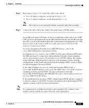
... For more information about the Cisco LRE 48 POTS Splitter (PS-1M-LRE-48), refer to the patch panel. 78-6461-04 Catalyst 2900 Series XL Hardware Installation Guide 2-41 Step 3 Connect the other telephone services are connected through a PBX switch, a Cisco LRE 48 POTS Splitter can connect directly... a telephone network is not required at all, a splitter is required to directly connect to the Cisco LRE CPE Hardware Installation Guide. Chapter 2 Installation Connecting to an LRE Port Step 2 Referring to Figure 2-30, secure the cable to the patch panel or POTS splitter. Note...
... For more information about the Cisco LRE 48 POTS Splitter (PS-1M-LRE-48), refer to the patch panel. 78-6461-04 Catalyst 2900 Series XL Hardware Installation Guide 2-41 Step 3 Connect the other telephone services are connected through a PBX switch, a Cisco LRE 48 POTS Splitter can connect directly... a telephone network is not required at all, a splitter is required to directly connect to the Cisco LRE CPE Hardware Installation Guide. Chapter 2 Installation Connecting to an LRE Port Step 2 Referring to Figure 2-30, secure the cable to the patch panel or POTS splitter. Note...

Hardware Installation Guide
Page 109
...20, tip/ring 21, tip/ring 22, tip/ring 23, tip/ring 24, tip/ring no connect - On a Catalyst 2912 LRE XL switch, only circuits 1 to a console PC or terminal. Console Port The console port uses an 8-pin RJ-45 connector, as shown in Figure B-7 and described in Table B-2. Appendix B Connectors and Cable ... tip/ring 23, 48 11, tip/ring 24, 49 12, tip/ring 25, 50 13, tip/ring - The supplied RJ-45-to-RJ-45 rollover cable and adapters connect the console port of the switch to 12 are valid. Note Table B-1 shows the pinouts for the console port. 78-6461-04 Catalyst 2900 Series XL...
...20, tip/ring 21, tip/ring 22, tip/ring 23, tip/ring 24, tip/ring no connect - On a Catalyst 2912 LRE XL switch, only circuits 1 to a console PC or terminal. Console Port The console port uses an 8-pin RJ-45 connector, as shown in Figure B-7 and described in Table B-2. Appendix B Connectors and Cable ... tip/ring 23, 48 11, tip/ring 24, 49 12, tip/ring 25, 50 13, tip/ring - The supplied RJ-45-to-RJ-45 rollover cable and adapters connect the console port of the switch to 12 are valid. Note Table B-1 shows the pinouts for the console port. 78-6461-04 Catalyst 2900 Series XL...


