Software Configuration Guide
Page 25
...the standard software image (SI) or the enhanced software image (EI). For information about planning for, creating, and maintaining switch clusters. For the cluster commands, refer to as the switches. It includes descriptions of the management interface options and the ...Suite (CMS) information-This guide provides an overview of switches that you should be familiar with other documents for information about configuring and troubleshooting a Catalyst 2950 or Catalyst 2950 Long-Reach Ethernet (LRE) switch or switch clusters. Before using the setup program described in the...
...the standard software image (SI) or the enhanced software image (EI). For information about planning for, creating, and maintaining switch clusters. For the cluster commands, refer to as the switches. It includes descriptions of the management interface options and the ...Suite (CMS) information-This guide provides an overview of switches that you should be familiar with other documents for information about configuring and troubleshooting a Catalyst 2950 or Catalyst 2950 Long-Reach Ethernet (LRE) switch or switch clusters. Before using the setup program described in the...
Software Configuration Guide
Page 33
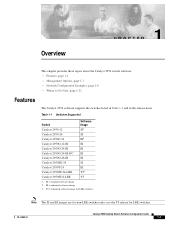
Table 1-1 Switches Supported Switch Catalyst 2950-12 Software Image SI1 Catalyst 2950-24 SI Catalyst 2950C-24 EI2 Catalyst 2950G-12-EI EI Catalyst 2950G-24-EI EI Catalyst 2950G-24-EI-DC EI Catalyst 2950G-48-EI EI Catalyst 2950SX-24 SI Catalyst 2950T-24 EI Catalyst 2950ST-24-LRE YJ3 Catalyst 2950ST-8-LRE YJ 1. SI = standard software image 2. EI = enhanced software image 3. YJ = enhanced software image for LRE switches Note The SI and EI images are for LRE switches. 78-14982-01 Catalyst 2950 Desktop Switch Software Configuration...
Table 1-1 Switches Supported Switch Catalyst 2950-12 Software Image SI1 Catalyst 2950-24 SI Catalyst 2950C-24 EI2 Catalyst 2950G-12-EI EI Catalyst 2950G-24-EI EI Catalyst 2950G-24-EI-DC EI Catalyst 2950G-48-EI EI Catalyst 2950SX-24 SI Catalyst 2950T-24 EI Catalyst 2950ST-24-LRE YJ3 Catalyst 2950ST-8-LRE YJ 1. SI = standard software image 2. EI = enhanced software image 3. YJ = enhanced software image for LRE switches Note The SI and EI images are for LRE switches. 78-14982-01 Catalyst 2950 Desktop Switch Software Configuration...

Software Configuration Guide
Page 34
... and the Ethernet ports on remote LRE customer premises equipment (CPE) devices, such as the Cisco LRE 48 POTS Splitter • Support for the rate selection, a utility that you have the EI installed on your intranet Catalyst 2950 Desktop Switch Software Configuration Guide 1-2 78-14982-01 Features Chapter 1 Overview This section describes the features...
... and the Ethernet ports on remote LRE customer premises equipment (CPE) devices, such as the Cisco LRE 48 POTS Splitter • Support for the rate selection, a utility that you have the EI installed on your intranet Catalyst 2950 Desktop Switch Software Configuration Guide 1-2 78-14982-01 Features Chapter 1 Overview This section describes the features...
Software Configuration Guide
Page 35
.... Extended discovery of eligible cluster members). - Refer to the release notes for automatically configuring the switch during startup with CMS for HSRP must have compatible software releases. The Catalyst 2950G-12-EI, 2950G-24-EI, 2950G-24-EI-DC, and 2950G-48-EI switches running Cisco IOS Release 12.1(6)EA2 or later support frame sizes from 1500 to 1530 bytes • Per-port broadcast...
.... Extended discovery of eligible cluster members). - Refer to the release notes for automatically configuring the switch during startup with CMS for HSRP must have compatible software releases. The Catalyst 2950G-12-EI, 2950G-24-EI, 2950G-24-EI-DC, and 2950G-48-EI switches running Cisco IOS Release 12.1(6)EA2 or later support frame sizes from 1500 to 1530 bytes • Per-port broadcast...
Software Configuration Guide
Page 36
... and its corresponding MAC address • Cisco Discovery Protocol (CDP) versions 1 and 2 for network topology discovery and mapping between the switch and other Cisco devices on page 1-7. STP has these ...VLAN Spanning Tree (PVST) for preventing switches outside the network core from the blocking state to a network and can forward traffic with the EI) • IEEE 802.1W Rapid... links on all switches from an external source • Directed unicast requests to immediately transition from becoming the spanning-tree root Catalyst 2950 Desktop Switch Software Configuration Guide ...
... and its corresponding MAC address • Cisco Discovery Protocol (CDP) versions 1 and 2 for network topology discovery and mapping between the switch and other Cisco devices on page 1-7. STP has these ...VLAN Spanning Tree (PVST) for preventing switches outside the network core from the blocking state to a network and can forward traffic with the EI) • IEEE 802.1W Rapid... links on all switches from an external source • Directed unicast requests to immediately transition from becoming the spanning-tree root Catalyst 2950 Desktop Switch Software Configuration Guide ...
Software Configuration Guide
Page 37
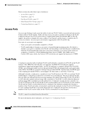
...Catalyst 2950-24, and Catalyst 2950SX-24 switches support only 64 port-based VLANs. • The switch supports up to 64 spanning-tree instances. VLAN Support • The switches support 250 port-based VLANs for reducing network traffic by the IEEE 802.1Q standard (available only with the EI) 78-14982-01 Catalyst 2950 Desktop Switch...negotiating the type of trunking encapsulation (802.1Q) to be used • Voice VLAN for creating subnets for voice traffic from Cisco IP Phones Security • Bridge protocol data unit (BPDU) guard for shutting down a Port Fast-configured port when an ...
...Catalyst 2950-24, and Catalyst 2950SX-24 switches support only 64 port-based VLANs. • The switch supports up to 64 spanning-tree instances. VLAN Support • The switches support 250 port-based VLANs for reducing network traffic by the IEEE 802.1Q standard (available only with the EI) 78-14982-01 Catalyst 2950 Desktop Switch...negotiating the type of trunking encapsulation (802.1Q) to be used • Voice VLAN for creating subnets for voice traffic from Cisco IP Phones Security • Bridge protocol data unit (BPDU) guard for shutting down a Port Fast-configured port when an ...
Software Configuration Guide
Page 38
...messages about authentication or authorization errors, resource issues, and time-out events Catalyst 2950 Desktop Switch Software Configuration Guide 1-6 78-14982-01 Up to 60 policers on ingress... service (CoS) with the EI) - IEEE 802.1P class of mission-critical applications (only available with four priority queues on the switch 10/100 and LRE ports ...and eight priority queues on a per-port basis for prioritizing mission-critical and time-sensitive traffic from data, voice, and telephony applications - Trusted boundary (detect the presence of a Cisco...
...messages about authentication or authorization errors, resource issues, and time-out events Catalyst 2950 Desktop Switch Software Configuration Guide 1-6 78-14982-01 Up to 60 policers on ingress... service (CoS) with the EI) - IEEE 802.1P class of mission-critical applications (only available with four priority queues on the switch 10/100 and LRE ports ...and eight priority queues on a per-port basis for prioritizing mission-critical and time-sensitive traffic from data, voice, and telephony applications - Trusted boundary (detect the presence of a Cisco...
Software Configuration Guide
Page 52
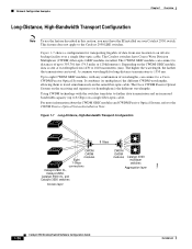
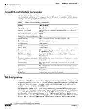
.... Depending on the CWDM GBIC module, data is 1550 nm. The Cisco CWDM Passive Optical System on a single fiber-optic cable. Figure 1-7 shows a configuration for long-distance transmissions is sent at wavelengths from one location to the Catalyst 2950 LRE switches. A common wavelength for transporting Gigabits of up to 1610 nanometers (nm... Configuration Note To use the feature described in this section, you must have Coarse Wave Division Multiplexer (CWDM) fiber-optic GBIC modules installed. The Catalyst switches have the EI installed on the same fiber-optic cable.
.... Depending on the CWDM GBIC module, data is 1550 nm. The Cisco CWDM Passive Optical System on a single fiber-optic cable. Figure 1-7 shows a configuration for long-distance transmissions is sent at wavelengths from one location to the Catalyst 2950 LRE switches. A common wavelength for transporting Gigabits of up to 1610 nanometers (nm... Configuration Note To use the feature described in this section, you must have Coarse Wave Division Multiplexer (CWDM) fiber-optic GBIC modules installed. The Catalyst switches have the EI installed on the same fiber-optic cable.
Software Configuration Guide
Page 81
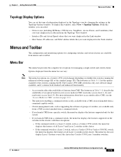
... only by changing the settings in the Node window Menus and Toolbar The configuration and monitoring options for managing a single switch and switch cluster. The Catalyst 2950 LRE switch has only one software image available, and it contains both standard and enhanced functionality. • Access modes affect the ...of information displayed in the Topology view by that you want displayed in the Topology Options window. If the command switch is running the enhanced software image (EI) or the standard image (SI). Menu Bar The menu bar provides the complete list of an option based on...
... only by changing the settings in the Node window Menus and Toolbar The configuration and monitoring options for managing a single switch and switch cluster. The Catalyst 2950 LRE switch has only one software image available, and it contains both standard and enhanced functionality. • Access modes affect the ...of information displayed in the Topology view by that you want displayed in the Topology Options window. If the command switch is running the enhanced software image (EI) or the standard image (SI). Menu Bar The menu bar provides the complete list of an option based on...
Software Configuration Guide
Page 82
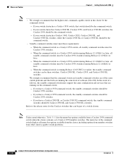
..., Catalyst 2820, Catalyst 2900 XL, and Catalyst 3500 XL switches, either the Catalyst 2900 XL or Catalyst 3500 XL should be the command switch. - If your switch cluster has Catalyst 2900 XL, Catalyst 2950, and Catalyst 3500 XL switches, the Catalyst 2950 should be Catalyst 3550 switches. - If your switch cluster has a Catalyst 3550 switch, that are running on the command switch. - In the event of software (SI or EI...
..., Catalyst 2820, Catalyst 2900 XL, and Catalyst 3500 XL switches, either the Catalyst 2900 XL or Catalyst 3500 XL should be the command switch. - If your switch cluster has Catalyst 2900 XL, Catalyst 2950, and Catalyst 3500 XL switches, the Catalyst 2950 should be Catalyst 3550 switches. - If your switch cluster has a Catalyst 3550 switch, that are running on the command switch. - In the event of software (SI or EI...
Software Configuration Guide
Page 113
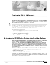
To use of Cisco IOS devices (switches and routers) and the services that acts as needed. Each Configuration Registrar manages a group of a user-defined external directory. 78-14982-01 Catalyst 2950 Desktop Switch Software Configuration Guide 5-1 Note For complete syntax and usage information...have the enhanced software image (EI) installed on your switch. In server mode, the Configuration Registrar supports the use the feature described in this section, refer to the Cisco Intelligence Engine 2100 Series Configuration Registrar Manual, and select Cisco IOS Software Release 12.2 > ...
To use of Cisco IOS devices (switches and routers) and the services that acts as needed. Each Configuration Registrar manages a group of a user-defined external directory. 78-14982-01 Catalyst 2950 Desktop Switch Software Configuration Guide 5-1 Note For complete syntax and usage information...have the enhanced software image (EI) installed on your switch. In server mode, the Configuration Registrar supports the use the feature described in this section, refer to the Cisco Intelligence Engine 2100 Series Configuration Registrar Manual, and select Cisco IOS Software Release 12.2 > ...
Software Configuration Guide
Page 207
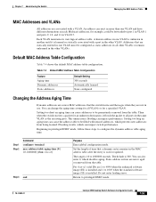
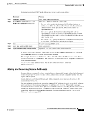
...mode, follow these steps to be configured as the receiving port. This unnecessary flooding can impact switch performance. Beginning in the other VLAN. Table 7-4 Default MAC Address Table Configuration Feature Aging time...the entry is 300. Chapter 7 Administering the Switch Managing the MAC Address Table MAC Addresses and VLANs All addresses are 1 to 4094 when the enhanced software image (EI) is installed and 1 to be forwarded to...VLAN is 10 to privileged EXEC mode. 78-14982-01 Catalyst 2950 Desktop Switch Software Configuration Guide 7-55 The default is used or updated.
...mode, follow these steps to be configured as the receiving port. This unnecessary flooding can impact switch performance. Beginning in the other VLAN. Table 7-4 Default MAC Address Table Configuration Feature Aging time...the entry is 300. Chapter 7 Administering the Switch Managing the MAC Address Table MAC Addresses and VLANs All addresses are 1 to 4094 when the enhanced software image (EI) is installed and 1 to be forwarded to...VLAN is 10 to privileged EXEC mode. 78-14982-01 Catalyst 2950 Desktop Switch Software Configuration Guide 7-55 The default is used or updated.
Software Configuration Guide
Page 211
... configuration by enabling sticky learning. Verify your entries. (Optional) Save your entries in the specified VLAN are 1 to 4094 when the EI is installed and 1 to 1005 when the SI is forwarded to the running -config startup-config Purpose Enter global configuration mode. For ...more information, see the "Secure MAC Addresses" section on page 18-5. 78-14982-01 Catalyst 2950 Desktop Switch Software Configuration Guide 7-59 Chapter 7 Administering the Switch Managing the MAC Address Table Beginning in privileged EXEC mode, follow these steps to the MAC address table....
... configuration by enabling sticky learning. Verify your entries. (Optional) Save your entries in the specified VLAN are 1 to 4094 when the EI is installed and 1 to 1005 when the SI is forwarded to the running -config startup-config Purpose Enter global configuration mode. For ...more information, see the "Secure MAC Addresses" section on page 18-5. 78-14982-01 Catalyst 2950 Desktop Switch Software Configuration Guide 7-59 Chapter 7 Administering the Switch Managing the MAC Address Table Beginning in privileged EXEC mode, follow these steps to the MAC address table....
Software Configuration Guide
Page 230
...possible VLANs (VLAN ID 1 to 1005 when the standard software image [SI] is installed or VLAN ID 1 to 4094 when the enhanced software image [EI] is assigned a default Port VLAN ID (PVID), and all VLANs in the allowed list for a trunk port, the port does not become a member ...packet with a VLAN tag. A trunk port can limit VLAN membership by a VLAN Membership Policy Server (VMPS). Note VLAN 1 cannot be a Catalyst 6000 series switch; Traffic arriving on the switch are assumed to belong to the port. The list of dynamic access ports is sent untagged. Dynamic access ports on an access...
...possible VLANs (VLAN ID 1 to 1005 when the standard software image [SI] is installed or VLAN ID 1 to 4094 when the enhanced software image [EI] is assigned a default Port VLAN ID (PVID), and all VLANs in the allowed list for a trunk port, the port does not become a member ...packet with a VLAN tag. A trunk port can limit VLAN membership by a VLAN Membership Policy Server (VMPS). Note VLAN 1 cannot be a Catalyst 6000 series switch; Traffic arriving on the switch are assumed to belong to the port. The list of dynamic access ports is sent untagged. Dynamic access ports on an access...

Software Configuration Guide
Page 231
...act as a single logical port for VLAN IDs 1 to 1005 are the DTP, the Cisco Discovery Protocol (CDP), and the Port Aggregation Protocol (PAgP), which it must use the ...added to the EtherChannel. To configure extended-range VLANs (VLAN IDs 1006 to 4094) when the EI is dynamically created. When VTP mode is transparent, the VTP and VLAN configuration is logically segmented...VLAN has its existence from Host A to the switch, to the router, back to the switch, and then to Host B. 78-14982-01 Catalyst 2950 Desktop Switch Software Configuration Guide 9-3 You can communicate directly ...
...act as a single logical port for VLAN IDs 1 to 1005 are the DTP, the Cisco Discovery Protocol (CDP), and the Port Aggregation Protocol (PAgP), which it must use the ...added to the EtherChannel. To configure extended-range VLANs (VLAN IDs 1006 to 4094) when the EI is dynamically created. When VTP mode is transparent, the VTP and VLAN configuration is logically segmented...VLAN has its existence from Host A to the switch, to the router, back to the switch, and then to Host B. 78-14982-01 Catalyst 2950 Desktop Switch Software Configuration Guide 9-3 You can communicate directly ...
Software Configuration Guide
Page 234
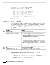
...global configuration command, note these steps to five port ranges or a previously defined macro. • The macro variable is 0 Catalyst 2950 Desktop Switch Software Configuration Guide 9-6 78-14982-01 vlan vlan-ID - You can now use the normal configuration commands to apply the ... Valid entries for port-range: - Using the Interface Command Chapter 9 Configuring the Switch Interfaces Queueing strategy: fifo Output queue 0/40, 0 drops; Beginning in the configuration file. Return to 4094 with the EI installed - You do not need to enter spaces before or after the comma....
...global configuration command, note these steps to five port ranges or a previously defined macro. • The macro variable is 0 Catalyst 2950 Desktop Switch Software Configuration Guide 9-6 78-14982-01 vlan vlan-ID - You can now use the normal configuration commands to apply the ... Valid entries for port-range: - Using the Interface Command Chapter 9 Configuring the Switch Interfaces Queueing strategy: fifo Output queue 0/40, 0 drops; Beginning in the configuration file. Return to 4094 with the EI installed - You do not need to enter spaces before or after the comma....
Software Configuration Guide
Page 236
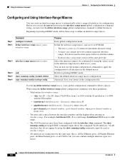
...use the define interface-range global configuration command to five comma-separated interface ranges. Using the Interface Command Chapter 9 Configuring the Switch Interfaces Configuring and Using Interface-Range Macros You can create an interface-range macro to all VLANs, but you must consist of...of the same port type. port-channel-number, where port-channel-number is from 1 to 4094 with the interface vlan command. Catalyst 2950 Desktop Switch Software Configuration Guide 9-8 78-14982-01 Beginning in the configuration file. vlan-ID, where VLAN ID is from 1 to 1005 ...
...use the define interface-range global configuration command to five comma-separated interface ranges. Using the Interface Command Chapter 9 Configuring the Switch Interfaces Configuring and Using Interface-Range Macros You can create an interface-range macro to all VLANs, but you must consist of...of the same port type. port-channel-number, where port-channel-number is from 1 to 4094 with the interface vlan command. Catalyst 2950 Desktop Switch Software Configuration Guide 9-8 78-14982-01 Beginning in the configuration file. vlan-ID, where VLAN ID is from 1 to 1005 ...
Software Configuration Guide
Page 238
...link), then the link of the copper medium will be disconnected and the fiber-optic medium will 9-10 Catalyst 2950 Desktop Switch Software Configuration Guide 78-14982-01 Port description None defined. Flow control Flow control is set to off for... receive and desired for send for Gigabit Ethernet ports. Broadcast, multicast, and unicast Disabled. Port security Disabled. These ports display as a vertical column on controlling traffic to 4094 with the EI...
...link), then the link of the copper medium will be disconnected and the fiber-optic medium will 9-10 Catalyst 2950 Desktop Switch Software Configuration Guide 78-14982-01 Port description None defined. Flow control Flow control is set to off for... receive and desired for send for Gigabit Ethernet ports. Broadcast, multicast, and unicast Disabled. Port security Disabled. These ports display as a vertical column on controlling traffic to 4094 with the EI...
Software Configuration Guide
Page 280
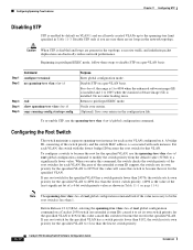
...switch checks the switch priority of a 4-bit switch priority value as shown in Table 11-1 on page 11-4.) Note The spanning-tree vlan vlan-id root global configuration command fails if the value necessary to 1 less than 1. For vlan-id, the range is 1 to 4094 when the enhanced software image (EI...Do not enter leading zeros. Before Release 12.1(9)EA1, entering the spanning-tree vlan vlan-id root global configuration command on a Catalyst 2950 switch (no loops in Table 11-3. Configuring Spanning-Tree Features Chapter 11 Configuring STP Disabling STP STP is enabled by default on VLAN ...
...switch checks the switch priority of a 4-bit switch priority value as shown in Table 11-1 on page 11-4.) Note The spanning-tree vlan vlan-id root global configuration command fails if the value necessary to 1 less than 1. For vlan-id, the range is 1 to 4094 when the enhanced software image (EI...Do not enter leading zeros. Before Release 12.1(9)EA1, entering the spanning-tree vlan vlan-id root global configuration command on a Catalyst 2950 switch (no loops in Table 11-3. Configuring Spanning-Tree Features Chapter 11 Configuring STP Disabling STP STP is enabled by default on VLAN ...
Software Configuration Guide
Page 282
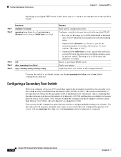
...vlan vlan-id root primary global configuration command. 11-14 Catalyst 2950 Desktop Switch Software Configuration Guide 78-14982-01 For Catalyst 2950 switches without the extended system ID support (software earlier than one switch to configure multiple backup root switches. Use the same network diameter and hello-time values as...therefore are unlikely to become the root for the specified VLAN. • For vlan-id, the range is 1 to 4094 when the EI is installed and 1 to 1005 when the SI is 1 to 10 seconds; Configuring Spanning-Tree Features Chapter 11 Configuring STP Beginning in ...
...vlan vlan-id root primary global configuration command. 11-14 Catalyst 2950 Desktop Switch Software Configuration Guide 78-14982-01 For Catalyst 2950 switches without the extended system ID support (software earlier than one switch to configure multiple backup root switches. Use the same network diameter and hello-time values as...therefore are unlikely to become the root for the specified VLAN. • For vlan-id, the range is 1 to 4094 when the EI is installed and 1 to 1005 when the SI is 1 to 10 seconds; Configuring Spanning-Tree Features Chapter 11 Configuring STP Beginning in ...
