Software Configuration Guide
Page 7
...Switch-Specific Features in Switch Clusters 6-19 Creating a Switch Cluster 6-19 Enabling a Command Switch 6-19 Adding Member Switches 6-20 Creating a Cluster Standby Group 6-22 Verifying a Switch Cluster 6-24 Using the CLI to Manage Switch Clusters 6-25 Catalyst 1900 and Catalyst 2820 CLI Considerations 6-25 Using SNMP to Manage Switch Clusters 6-26 Administering the Switch... 7-10 Controlling Switch Access with TACACS+ 7-10 Understanding TACACS+ 7-10 TACACS+ Operation 7-12 Configuring TACACS+ 7-12 Default TACACS+ Configuration 7-13 Catalyst 2950 Desktop Switch Software Configuration Guide vii
...Switch-Specific Features in Switch Clusters 6-19 Creating a Switch Cluster 6-19 Enabling a Command Switch 6-19 Adding Member Switches 6-20 Creating a Cluster Standby Group 6-22 Verifying a Switch Cluster 6-24 Using the CLI to Manage Switch Clusters 6-25 Catalyst 1900 and Catalyst 2820 CLI Considerations 6-25 Using SNMP to Manage Switch Clusters 6-26 Administering the Switch... 7-10 Controlling Switch Access with TACACS+ 7-10 Understanding TACACS+ 7-10 TACACS+ Operation 7-12 Configuring TACACS+ 7-12 Default TACACS+ Configuration 7-13 Catalyst 2950 Desktop Switch Software Configuration Guide vii

Software Configuration Guide
Page 14
... STP Port Priorities 14-21 Load Sharing Using STP Path Cost 14-23 Configuring VMPS 14-24 Understanding VMPS 14-25 Dynamic Port VLAN Membership 14-25 VMPS Database Configuration File 14-26 Default VMPS Configuration 14-27 VMPS Configuration Guidelines 14-28 Catalyst 2950 Desktop Switch Software Configuration Guide xiv 78-14982-01
... STP Port Priorities 14-21 Load Sharing Using STP Path Cost 14-23 Configuring VMPS 14-24 Understanding VMPS 14-25 Dynamic Port VLAN Membership 14-25 VMPS Database Configuration File 14-26 Default VMPS Configuration 14-27 VMPS Configuration Guidelines 14-28 Catalyst 2950 Desktop Switch Software Configuration Guide xiv 78-14982-01

Software Configuration Guide
Page 16
Contents 17 C H A P T E R Default Voice VLAN Configuration 16-2 Voice VLAN Configuration Guidelines 16-3 Configuring a Port to Connect to a Cisco 7960 IP Phone 16-3 Configuring Ports to Carry Voice Traffic in 802.1Q Frames 16-4 Configuring Ports to Carry Voice Traffic in 802.1P Priority ...-21 Configuring IGMP Profiles 17-21 Applying IGMP Profiles 17-22 Setting the Maximum Number of IGMP Groups 17-23 Displaying IGMP Filtering Configuration 17-24 Catalyst 2950 Desktop Switch Software Configuration Guide xvi 78-14982-01
Contents 17 C H A P T E R Default Voice VLAN Configuration 16-2 Voice VLAN Configuration Guidelines 16-3 Configuring a Port to Connect to a Cisco 7960 IP Phone 16-3 Configuring Ports to Carry Voice Traffic in 802.1Q Frames 16-4 Configuring Ports to Carry Voice Traffic in 802.1P Priority ...-21 Configuring IGMP Profiles 17-21 Applying IGMP Profiles 17-22 Setting the Maximum Number of IGMP Groups 17-23 Displaying IGMP Filtering Configuration 17-24 Catalyst 2950 Desktop Switch Software Configuration Guide xvi 78-14982-01

Software Configuration Guide
Page 19
... 24-13 SNMP Examples 24-14 Displaying SNMP Status 24-15 Configuring Network Security with ACLs 25-1 Understanding ACLs 25-2 Handling Fragmented and Unfragmented Traffic 25-3 Understanding Access Control Parameters 25-4 Guidelines for Applying ACLs to Physical Interfaces 25-6 Configuring ACLs 25-6 Unsupported Features 25-7 Creating Standard and Extended IP ACLs 25-7 Catalyst 2950 Desktop Switch...
... 24-13 SNMP Examples 24-14 Displaying SNMP Status 24-15 Configuring Network Security with ACLs 25-1 Understanding ACLs 25-2 Handling Fragmented and Unfragmented Traffic 25-3 Understanding Access Control Parameters 25-4 Guidelines for Applying ACLs to Physical Interfaces 25-6 Configuring ACLs 25-6 Unsupported Features 25-7 Creating Standard and Extended IP ACLs 25-7 Catalyst 2950 Desktop Switch...

Software Configuration Guide
Page 21
... 26-16 Classifying Traffic by Using Class Maps 26-20 Classifying, Policing, and Marking Traffic by Using Policy Maps 26-21 Configuring CoS Maps 26-24 Configuring the CoS-to-DSCP Map 26-25 Configuring the DSCP-to-CoS Map 26-26 Configuring CoS and WRR 26-27 Configuring CoS Priority...-11 Troubleshooting 28-1 LRE Statistics 28-1 Using Recovery Procedures 28-6 Recovering from Corrupted Software 28-6 Recovering from a Lost or Forgotten Password 28-6 Recovering from a Command Switch Failure 28-8 Catalyst 2950 Desktop Switch Software Configuration Guide xxi
... 26-16 Classifying Traffic by Using Class Maps 26-20 Classifying, Policing, and Marking Traffic by Using Policy Maps 26-21 Configuring CoS Maps 26-24 Configuring the CoS-to-DSCP Map 26-25 Configuring the DSCP-to-CoS Map 26-26 Configuring CoS and WRR 26-27 Configuring CoS Priority...-11 Troubleshooting 28-1 LRE Statistics 28-1 Using Recovery Procedures 28-6 Recovering from Corrupted Software 28-6 Recovering from a Lost or Forgotten Password 28-6 Recovering from a Command Switch Failure 28-8 Catalyst 2950 Desktop Switch Software Configuration Guide xxi

Software Configuration Guide
Page 23
... Deleting a Stored Configuration File B-20 Working with Software Images B-20 Image Location on the Switch B-20 tar File Format of Images on a Server or Cisco.com B-21 Copying Image Files By Using TFTP B-22 Preparing to Download or Upload an ...Image File By Using TFTP B-22 Downloading an Image File By Using TFTP B-23 Uploading an Image File By Using TFTP B-24 Copying Image...Using RCP B-30 Uploading an Image File By Using RCP B-32 78-14982-01 Catalyst 2950 Desktop Switch Software Configuration Guide xxiii
... Deleting a Stored Configuration File B-20 Working with Software Images B-20 Image Location on the Switch B-20 tar File Format of Images on a Server or Cisco.com B-21 Copying Image Files By Using TFTP B-22 Preparing to Download or Upload an ...Image File By Using TFTP B-22 Downloading an Image File By Using TFTP B-23 Uploading an Image File By Using TFTP B-24 Copying Image...Using RCP B-30 Uploading an Image File By Using RCP B-32 78-14982-01 Catalyst 2950 Desktop Switch Software Configuration Guide xxiii
Software Configuration Guide
Page 27
...phone. The RMON feature, which select network traffic for managing VLANs. Catalyst 2950 Desktop Switch Software Configuration Guide xxvii It describes the interface global configuration command and provides... a local IGMP snooping feature available on a switch; Chapter 22, "Configuring RMON," describes how to control multicast group membership. Chapter 24, "Configuring SNMP," describes how to use IGMP...network. Chapter 20, "Configuring CDP," describes how to configure Cisco Discovery Protocol (CDP) on the switch. It describes how to configure community strings, enable trap managers...
...phone. The RMON feature, which select network traffic for managing VLANs. Catalyst 2950 Desktop Switch Software Configuration Guide xxvii It describes the interface global configuration command and provides... a local IGMP snooping feature available on a switch; Chapter 22, "Configuring RMON," describes how to control multicast group membership. Chapter 24, "Configuring SNMP," describes how to use IGMP...network. Chapter 20, "Configuring CDP," describes how to configure Cisco Discovery Protocol (CDP) on the switch. It describes how to configure community strings, enable trap managers...
Software Configuration Guide
Page 33
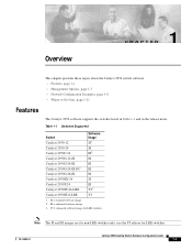
... and EI images are for LRE switches. 78-14982-01 Catalyst 2950 Desktop Switch Software Configuration Guide 1-1 SI = standard software image 2. Table 1-1 Switches Supported Switch Catalyst 2950-12 Software Image SI1 Catalyst 2950-24 SI Catalyst 2950C-24 EI2 Catalyst 2950G-12-EI EI Catalyst 2950G-24-EI EI Catalyst 2950G-24-EI-DC EI Catalyst 2950G-48-EI EI Catalyst 2950SX-24 SI Catalyst 2950T-24 EI Catalyst 2950ST-24-LRE YJ3 Catalyst 2950ST-8-LRE YJ 1. use the YJ...
... and EI images are for LRE switches. 78-14982-01 Catalyst 2950 Desktop Switch Software Configuration Guide 1-1 SI = standard software image 2. Table 1-1 Switches Supported Switch Catalyst 2950-12 Software Image SI1 Catalyst 2950-24 SI Catalyst 2950C-24 EI2 Catalyst 2950G-12-EI EI Catalyst 2950G-24-EI EI Catalyst 2950G-24-EI-DC EI Catalyst 2950G-48-EI EI Catalyst 2950SX-24 SI Catalyst 2950T-24 EI Catalyst 2950ST-24-LRE YJ3 Catalyst 2950ST-8-LRE YJ 1. use the YJ...
Software Configuration Guide
Page 35
... Internet Group Management Protocol (IGMP) snooping support to the command switch. • Hot Standby Router Protocol (HSRP) for this switch. 78-14982-01 Catalyst 2950 Desktop Switch Software Configuration Guide 1-3 The redundant command switches used with CMS for HSRP must have compatible software releases. Automatic ...servers • Support for the CMS, cluster hardware, software, and browser requirements. The Catalyst 2950G-12-EI, 2950G-24-EI, 2950G-24-EI-DC, and 2950G-48-EI switches running Cisco IOS Release 12.1(6)EA2 or later support frame sizes from 1500 to 1530 bytes •...
... Internet Group Management Protocol (IGMP) snooping support to the command switch. • Hot Standby Router Protocol (HSRP) for this switch. 78-14982-01 Catalyst 2950 Desktop Switch Software Configuration Guide 1-3 The redundant command switches used with CMS for HSRP must have compatible software releases. Automatic ...servers • Support for the CMS, cluster hardware, software, and browser requirements. The Catalyst 2950G-12-EI, 2950G-24-EI, 2950G-24-EI-DC, and 2950G-48-EI switches running Cisco IOS Release 12.1(6)EA2 or later support frame sizes from 1500 to 1530 bytes •...
Software Configuration Guide
Page 37
...for negotiating the type of trunking encapsulation (802.1Q) to be used • Voice VLAN for creating subnets for voice traffic from Cisco IP Phones Security • Bridge protocol data unit (BPDU) guard for shutting down a Port Fast-configured port when an invalid ...for assigning users to VLANs associated with appropriate network resources, traffic patterns, and bandwidth Note The Catalyst 2950-12, Catalyst 2950-24, and Catalyst 2950SX-24 switches support only 64 port-based VLANs. • The switch supports up to the network • Standard and extended IP access control lists (ACLs) for...
...for negotiating the type of trunking encapsulation (802.1Q) to be used • Voice VLAN for creating subnets for voice traffic from Cisco IP Phones Security • Bridge protocol data unit (BPDU) guard for shutting down a Port Fast-configured port when an invalid ...for assigning users to VLANs associated with appropriate network resources, traffic patterns, and bandwidth Note The Catalyst 2950-12, Catalyst 2950-24, and Catalyst 2950SX-24 switches support only 64 port-based VLANs. • The switch supports up to the network • Standard and extended IP access control lists (ACLs) for...
Software Configuration Guide
Page 39
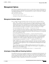
...switch and switch cluster members. This can configure and monitor the switch-on an individual basis or as part of a switch cluster-through its various management interfaces. CMS is the easiest interface to use Cisco switch clustering technology to manage up to 16 interconnected and supported Catalyst switches...station that is already installed on your network. 78-14982-01 Catalyst 2950 Desktop Switch Software Configuration Guide 1-7 You can manage the switch from any PC on the switch. Advantages of them to the switch, executing the configuration change, and logging the results. You ...
...switch and switch cluster members. This can configure and monitor the switch-on an individual basis or as part of a switch cluster-through its various management interfaces. CMS is the easiest interface to use Cisco switch clustering technology to manage up to 16 interconnected and supported Catalyst switches...station that is already installed on your network. 78-14982-01 Catalyst 2950 Desktop Switch Software Configuration Guide 1-7 You can manage the switch from any PC on the switch. Advantages of them to the switch, executing the configuration change, and logging the results. You ...
Software Configuration Guide
Page 71
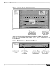
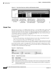
... port or link status. 78-14982-01 Catalyst 2950 Desktop Switch Software Configuration Guide 3-5 When CMS is launched from a 2950 Command Switch cluster1 10.1.1.2 Front Panel View 65718 Cluster tree. The color of the switch and connected RPS. Chapter 3 Getting Started ... from a standalone or noncommand member switch, the Front Panel view displays only the front panel of the specific switch (see Figure 3-5 for a 2950 switch and Figure 3-4 for a 2950 LRE switch). Figure 3-4 Front Panel View from a Standalone 2950 LRE Switch 2950-24 2950-24 86459 Left-click the Mode button...
... port or link status. 78-14982-01 Catalyst 2950 Desktop Switch Software Configuration Guide 3-5 When CMS is launched from a 2950 Command Switch cluster1 10.1.1.2 Front Panel View 65718 Cluster tree. The color of the switch and connected RPS. Chapter 3 Getting Started ... from a standalone or noncommand member switch, the Front Panel view displays only the front panel of the specific switch (see Figure 3-5 for a 2950 switch and Figure 3-4 for a 2950 LRE switch). Figure 3-4 Front Panel View from a Standalone 2950 LRE Switch 2950-24 2950-24 86459 Left-click the Mode button...
Software Configuration Guide
Page 72
...shows the name of the cluster and a list of the switch is not operating, or the switch is then highlighted with the member switch. If you can change connected RPS. The internal fan of its members. Catalyst 2950 Desktop Switch Software Configuration Guide 3-6 78-14982-01 port-related settings.... normally. The sequence of the cluster-tree icons (see Table 3-1). The front-panel image is receiving power from a 2950 non-LRE Standalone Switch 2950-24 2950-24 Left-click the Mode LEDs display the Right-click a port to button to view or change the sequence by selecting ...
...shows the name of the cluster and a list of the switch is not operating, or the switch is then highlighted with the member switch. If you can change connected RPS. The internal fan of its members. Catalyst 2950 Desktop Switch Software Configuration Guide 3-6 78-14982-01 port-related settings.... normally. The sequence of the cluster-tree icons (see Table 3-1). The front-panel image is receiving power from a 2950 non-LRE Standalone Switch 2950-24 2950-24 Left-click the Mode LEDs display the Right-click a port to button to view or change the sequence by selecting ...

Software Configuration Guide
Page 90
... Graphs Display graphs that plot the total bandwidth in CMS" section on page 3-31. 3-24 Catalyst 2950 Desktop Switch Software Configuration Guide 78-14982-01 Not available in use by the switch. Menus and Toolbar Chapter 3 Getting Started with CMS Table 3-17 Device Popup Menu of...Properties Display information about the device. 1. Available only from the cluster. Table 3-20 Device Popup Menu of a Candidate-Switch Icon (When the Candidate Switch Has an IP Address) Popup Menu Option Add to Cluster1 Device Manager2 Task Add a candidate to a cluster. Change the...
... Graphs Display graphs that plot the total bandwidth in CMS" section on page 3-31. 3-24 Catalyst 2950 Desktop Switch Software Configuration Guide 78-14982-01 Not available in use by the switch. Menus and Toolbar Chapter 3 Getting Started with CMS Table 3-17 Device Popup Menu of...Properties Display information about the device. 1. Available only from the cluster. Table 3-20 Device Popup Menu of a Candidate-Switch Icon (When the Candidate Switch Has an IP Address) Popup Menu Option Add to Cluster1 Device Manager2 Task Add a candidate to a cluster. Change the...

Software Configuration Guide
Page 108
Figure 4-3 DHCP-Based Autoconfiguration Network Example Switch 1 Switch 2 Switch 3 Switch 4 00e0.9f1e.2001 00e0.9f1e.2002 00e0.9f1e.2003 00e0.9f1e.2004 Cisco router 10.0.0.10 10.0.0.1 10.0.0.2 10.0.0.3 49066 DHCP server DNS server TFTP server (maritsu) Table 4-2 ...23 255.255.255.0 10.0.0.10 10.0.0.2 maritsu or 10.0.0.3 switch3-confg switch3 Switch-4 00e0.9f1e.2004 10.0.0.24 255.255.255.0 10.0.0.10 10.0.0.2 maritsu or 10.0.0.3 switch4-confg switch4 Catalyst 2950 Desktop Switch Software Configuration Guide 4-8 78-14982-01 Example Configuration Figure 4-3 shows a sample...
Figure 4-3 DHCP-Based Autoconfiguration Network Example Switch 1 Switch 2 Switch 3 Switch 4 00e0.9f1e.2001 00e0.9f1e.2002 00e0.9f1e.2003 00e0.9f1e.2004 Cisco router 10.0.0.10 10.0.0.1 10.0.0.2 10.0.0.3 49066 DHCP server DNS server TFTP server (maritsu) Table 4-2 ...23 255.255.255.0 10.0.0.10 10.0.0.2 maritsu or 10.0.0.3 switch3-confg switch3 Switch-4 00e0.9f1e.2004 10.0.0.24 255.255.255.0 10.0.0.10 10.0.0.2 maritsu or 10.0.0.3 switch4-confg switch4 Catalyst 2950 Desktop Switch Software Configuration Guide 4-8 78-14982-01 Example Configuration Figure 4-3 shows a sample...

Software Configuration Guide
Page 109
... ip host switch4 10.0.0.24 DHCP Client Configuration No configuration file is given in this display: prompt> cd /tftpserver/work /. Switches 2 through Switch 4. Configuration Explanation In Figure 4-3, Switch 1 reads its configuration file as shown in the DHCP server reply, Switch 1 reads the network...configuration file that corresponds to the switch based on UNIX) The TFTP server base directory is set to IP address 10.0.0.3. This directory contains the network-confg file used in the same way. 78-14982-01 Catalyst 2950 Desktop Switch Software Configuration Guide 4-9 TFTP ...
... ip host switch4 10.0.0.24 DHCP Client Configuration No configuration file is given in this display: prompt> cd /tftpserver/work /. Switches 2 through Switch 4. Configuration Explanation In Figure 4-3, Switch 1 reads its configuration file as shown in the DHCP server reply, Switch 1 reads the network...configuration file that corresponds to the switch based on UNIX) The TFTP server base directory is set to IP address 10.0.0.3. This directory contains the network-confg file used in the same way. 78-14982-01 Catalyst 2950 Desktop Switch Software Configuration Guide 4-9 TFTP ...

Software Configuration Guide
Page 142
... no command-switch password is Switch. Member switches only inherit the command-switch password. If a switch has a host name, it retains that host name even after it leaves the cluster. When a switch joins a cluster, it inherits the command-switch password and retains it when it joins a cluster. The default host name for those switches. 6-16 Catalyst 2950 Desktop Switch Software Configuration...
... no command-switch password is Switch. Member switches only inherit the command-switch password. If a switch has a host name, it retains that host name even after it leaves the cluster. When a switch joins a cluster, it inherits the command-switch password and retains it when it joins a cluster. The default host name for those switches. 6-16 Catalyst 2950 Desktop Switch Software Configuration...

Software Configuration Guide
Page 145
...-14982-01 Catalyst 2950 Desktop Switch Software Configuration Guide 6-19 You can only be member switches, and for switch clustering, including which ones can be command switches and which ones can enable a command switch, name the cluster, and assign an IP address and a password to create a cluster is in configurations. Chapter 6 Clustering Switches Creating a Switch Cluster Availability of Catalyst switches eligible...
...-14982-01 Catalyst 2950 Desktop Switch Software Configuration Guide 6-19 You can only be member switches, and for switch clustering, including which ones can be command switches and which ones can enable a command switch, name the cluster, and assign an IP address and a password to create a cluster is in configurations. Chapter 6 Clustering Switches Creating a Switch Cluster Availability of Catalyst switches eligible...

Software Configuration Guide
Page 147
... Cluster Window 2900-LRE-24-1 Select a switch, and click Add. If no password exists for the switch, leave this field blank. 65724 78-14982-01 Catalyst 2950 Desktop Switch Software Configuration Guide 6-21 When a candidate switch joins a cluster, it inherits the command-switch password. For more than one switch. Enter the password of the candidate switch. Press Ctrl and leftclick...
... Cluster Window 2900-LRE-24-1 Select a switch, and click Add. If no password exists for the switch, leave this field blank. 65724 78-14982-01 Catalyst 2950 Desktop Switch Software Configuration Guide 6-21 When a candidate switch joins a cluster, it inherits the command-switch password. For more than one switch. Enter the password of the candidate switch. Press Ctrl and leftclick...

Software Configuration Guide
Page 149
... group. Must be greater than or equal to 31 characters. Standby command switch. If you have set on Cisco.com. The default HSRP standby hold time interval should be a valid IP...switch • HC-Candidate switch that you use this information cannot be unique within the IP subnet. Note The HSRP standby hold time interval is 3 seconds. This address must be changed. 65726 78-14982-01 Catalyst 2950 Desktop Switch Software Configuration Guide 6-23 Figure 6-13 Standby Command Configuration Window 3550C (cisco WS-C3550-C-24, HC, ... Active command switch...
... group. Must be greater than or equal to 31 characters. Standby command switch. If you have set on Cisco.com. The default HSRP standby hold time interval should be a valid IP...switch • HC-Candidate switch that you use this information cannot be unique within the IP subnet. Note The HSRP standby hold time interval is 3 seconds. This address must be changed. 65726 78-14982-01 Catalyst 2950 Desktop Switch Software Configuration Guide 6-23 Figure 6-13 Standby Command Configuration Window 3550C (cisco WS-C3550-C-24, HC, ... Active command switch...
