
Hardware Installation Guide
Page 6
...12 RPS LED 1-13 Port LEDs and Modes 1-14 Module Slot LEDs 1-19 Rear-Panel Description 1-19 Power Connectors 1-21 Internal Power Supply Connector 1-21 DC Power Connector 1-21 Cisco... RPS Connector 1-22 Console Port 1-23 2 C H A P T E R Installation 2-1 Preparing for Installation 2-1 Warnings 2-1 EMC Regulatory Statements 2-4 U.S.A. 2-4 Taiwan 2-4 Japan 2-5 Korea 2-5 Hungary 2-6 Installation Guidelines 2-6 Verifying Package Contents 2-7 Installing the Switch on a Table or Shelf 2-9 Installing the Switch in a Rack 2-9 Removing Screws from the Switch 2-11 Attaching the Brackets to a Catalyst...
...12 RPS LED 1-13 Port LEDs and Modes 1-14 Module Slot LEDs 1-19 Rear-Panel Description 1-19 Power Connectors 1-21 Internal Power Supply Connector 1-21 DC Power Connector 1-21 Cisco... RPS Connector 1-22 Console Port 1-23 2 C H A P T E R Installation 2-1 Preparing for Installation 2-1 Warnings 2-1 EMC Regulatory Statements 2-4 U.S.A. 2-4 Taiwan 2-4 Japan 2-5 Korea 2-5 Hungary 2-6 Installation Guidelines 2-6 Verifying Package Contents 2-7 Installing the Switch on a Table or Shelf 2-9 Installing the Switch in a Rack 2-9 Removing Screws from the Switch 2-11 Attaching the Brackets to a Catalyst...

Hardware Installation Guide
Page 8
... Identifying a Rollover Cable B-6 Connecting to a PC B-6 Connecting to a Terminal B-7 Translated Safety Warnings C-1 Attaching the Cisco RPS (model PWR600-AC-RPS) C-1 Attaching the Cisco RPS (model PWR300-AC-RPS-N1) C-2 Qualified Personnel Warning C-3 Installation Warning C-4 Jewelry Removal Warning C-5 Stacking the ...Warning C-11 Circuit Breaker (15A) Warning C-12 Grounded Equipment Warning C-14 Supply Circuit Warning C-15 Voltage Warning C-16 Power Supply Warning C-17 Lightning Activity Warning C-19 Product Disposal Warning C-21 Catalyst 2900 Series XL Hardware Installation Guide viii 78...
... Identifying a Rollover Cable B-6 Connecting to a PC B-6 Connecting to a Terminal B-7 Translated Safety Warnings C-1 Attaching the Cisco RPS (model PWR600-AC-RPS) C-1 Attaching the Cisco RPS (model PWR300-AC-RPS-N1) C-2 Qualified Personnel Warning C-3 Installation Warning C-4 Jewelry Removal Warning C-5 Stacking the ...Warning C-11 Circuit Breaker (15A) Warning C-12 Grounded Equipment Warning C-14 Supply Circuit Warning C-15 Voltage Warning C-16 Power Supply Warning C-17 Lightning Activity Warning C-19 Product Disposal Warning C-21 Catalyst 2900 Series XL Hardware Installation Guide viii 78...

Hardware Installation Guide
Page 23
Chapter 1 Product Overview Figure 1-1 Catalyst 2900 Series XL Switches Version Number Description WS-C2912-LRE-XL 4 fixed autosensing 10/100 ports INPUT OUTPUT PWR PWR RESET TEMP FAN 9X 10X 11X 12X 12 LRE ports Cisco RPS 300 WS-C2924-LRE-XL 4 fixed autosensing 10/100 ports 24 LRE ports INPUT OUTPUT PWR PWR RESET... TEMP FAN 9X 10X 11X 12X Cisco RPS 300 WS-C2912-XL 12 fixed autosensing 10/100 ports MODE 1X 2X 3X 4X 5X 6X 7X 8X 9X 10X 10BaseT/100BASE-TX 11X 12X Catalyst 2900 SERIES XL WS-C2924C-XL 22 fixed autosensing 10/100 ports...
Chapter 1 Product Overview Figure 1-1 Catalyst 2900 Series XL Switches Version Number Description WS-C2912-LRE-XL 4 fixed autosensing 10/100 ports INPUT OUTPUT PWR PWR RESET TEMP FAN 9X 10X 11X 12X 12 LRE ports Cisco RPS 300 WS-C2924-LRE-XL 4 fixed autosensing 10/100 ports 24 LRE ports INPUT OUTPUT PWR PWR RESET... TEMP FAN 9X 10X 11X 12X Cisco RPS 300 WS-C2912-XL 12 fixed autosensing 10/100 ports MODE 1X 2X 3X 4X 5X 6X 7X 8X 9X 10X 10BaseT/100BASE-TX 11X 12X Catalyst 2900 SERIES XL WS-C2924C-XL 22 fixed autosensing 10/100 ports...
Hardware Installation Guide
Page 25
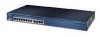
... XL 23 24 10/100 ports 100BASE-FX ports Figure 1-3 Catalyst 2900 XL 100BASE-FX ports and Module Slots Expansion slots 47286 12 1 MODE 2 3 Catalyst 2900 SERIES XL 4 5 100BASE-FX 6 7 8 9 10 11 12 100BASE-FX ports Figure 1-4 Catalyst 2900 LRE XL 10/100 and LRE Ports INPUT OUTPUT PWR ...PWR RESET TEMP FAN 9X 10X 11X 12X 10/100 ports LRE ports Catalyst 2900 LRE XL 48005 ...
... XL 23 24 10/100 ports 100BASE-FX ports Figure 1-3 Catalyst 2900 XL 100BASE-FX ports and Module Slots Expansion slots 47286 12 1 MODE 2 3 Catalyst 2900 SERIES XL 4 5 100BASE-FX 6 7 8 9 10 11 12 100BASE-FX ports Figure 1-4 Catalyst 2900 LRE XL 10/100 and LRE Ports INPUT OUTPUT PWR ...PWR RESET TEMP FAN 9X 10X 11X 12X 10/100 ports LRE ports Catalyst 2900 LRE XL 48005 ...

Hardware Installation Guide
Page 31
Chapter 1 Product Overview Figure 1-6 Catalyst 2912MF XL, 2924M XL, and 2924M XL DC LEDs 10BASE-FX port LEDs Front-Panel Description 12 1 MODE 2 3 4 5 100BASE-FX 6 7 System LED RPS LED Expansion slot status LED Port mode LED Mode button 48003 78-6461-04 Catalyst 2900 Series XL Hardware Installation Guide 1-11
Chapter 1 Product Overview Figure 1-6 Catalyst 2912MF XL, 2924M XL, and 2924M XL DC LEDs 10BASE-FX port LEDs Front-Panel Description 12 1 MODE 2 3 4 5 100BASE-FX 6 7 System LED RPS LED Expansion slot status LED Port mode LED Mode button 48003 78-6461-04 Catalyst 2900 Series XL Hardware Installation Guide 1-11

Hardware Installation Guide
Page 32
...1-2 System LED Color Off Green Amber System Status System is not functioning properly. System is receiving power and functioning properly. Front-Panel Description Figure 1-7 Catalyst 2912 LRE XL and 2924 LRE XL LEDs 10/100 port LEDs Chapter 1 Product Overview SYSTEM RPS MODE LRE STAT DUPLX SPEED Mode button 1X...operating normally. Table 1-2 lists the LED colors and their meanings. For information on the System LED colors during POST, see the "Powering On the Switch and Running POST" section on page 2-24. 1-12 Catalyst 2900 Series XL Hardware Installation Guide 78-6461-04
...1-2 System LED Color Off Green Amber System Status System is not functioning properly. System is receiving power and functioning properly. Front-Panel Description Figure 1-7 Catalyst 2912 LRE XL and 2924 LRE XL LEDs 10/100 port LEDs Chapter 1 Product Overview SYSTEM RPS MODE LRE STAT DUPLX SPEED Mode button 1X...operating normally. Table 1-2 lists the LED colors and their meanings. For information on the System LED colors during POST, see the "Powering On the Switch and Running POST" section on page 2-24. 1-12 Catalyst 2900 Series XL Hardware Installation Guide 78-6461-04
Hardware Installation Guide
Page 37
... from those on the LRE port. DUPLX Blinking amber Cisco IOS Release 12.0(5.x)WC1/ WC21 Activity on the LRE port. Green LRE link present on the LRE port. Cyan (off ) No LRE link present on Catalyst 2912 LRE XL and 2924 LRE XL Switches Port Mode Port LED Color Description LRE Note In LRE... mode, the 10/100 switch port LEDs continue to a LRE CPE...
... from those on the LRE port. DUPLX Blinking amber Cisco IOS Release 12.0(5.x)WC1/ WC21 Activity on the LRE port. Green LRE link present on the LRE port. Cyan (off ) No LRE link present on Catalyst 2912 LRE XL and 2924 LRE XL Switches Port Mode Port LED Color Description LRE Note In LRE... mode, the 10/100 switch port LEDs continue to a LRE CPE...

Hardware Installation Guide
Page 38
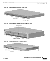
...is operating at 100 Mbps. 1. The LEDs on Catalyst 2900 LRE XL switches with Cisco IOS Release 12.0(5.x)WC4 or later do not provide information about the connected Cisco 575 LRE CPE devices. The LEDs on Catalyst 2900 LRE XL switches with this release or higher, use the Port Settings... Product Overview Table 1-7 Meanings of Port Status LEDs for Different Modes on Catalyst 2912 LRE XL and 2924 LRE XL Switches (continued) Port Mode SPEED Port LED Color Cisco IOS Release 12.0(5.x)WC1/ WC21 Description Cisco IOS Release 12.0(5.x)WC42 3 Cyan (off) Cyan (off) LRE port or remote CPE ...
...is operating at 100 Mbps. 1. The LEDs on Catalyst 2900 LRE XL switches with Cisco IOS Release 12.0(5.x)WC4 or later do not provide information about the connected Cisco 575 LRE CPE devices. The LEDs on Catalyst 2900 LRE XL switches with this release or higher, use the Port Settings... Product Overview Table 1-7 Meanings of Port Status LEDs for Different Modes on Catalyst 2912 LRE XL and 2924 LRE XL Switches (continued) Port Mode SPEED Port LED Color Cisco IOS Release 12.0(5.x)WC1/ WC21 Description Cisco IOS Release 12.0(5.x)WC42 3 Cyan (off) Cyan (off) LRE port or remote CPE ...

Hardware Installation Guide
Page 39
... LEDs Module slot LEDs (shown in Figure 1-6) show the status of a Catalyst 2900 XL and Catalyst 2900 LRE XL switches have an AC power connector, an RPS connector, and an RJ-45 console port. (See Figure 1-10 through Figure 1-12.) Figure 1-10 Catalyst 2912 XL, 2924 XL, and 2924C XL Rear Panel Fans 47295 11...
... LEDs Module slot LEDs (shown in Figure 1-6) show the status of a Catalyst 2900 XL and Catalyst 2900 LRE XL switches have an AC power connector, an RPS connector, and an RJ-45 console port. (See Figure 1-10 through Figure 1-12.) Figure 1-10 Catalyst 2912 XL, 2924 XL, and 2924C XL Rear Panel Fans 47295 11...

Hardware Installation Guide
Page 40
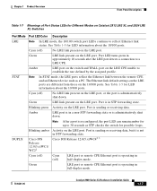
...-240V~ 5-3A 50/60Hz MAXIMUM 300W TOTAL OUTPUT DC OUTPUT AC power connector Redundant power system connector CONSOLE RJ-45 connector Figure 1-12 Catalyst 2924M XL and 2912 MF XL Rear Panel Fans CONSOLE RJ-45 connector +5DVSCPINEPCPO@IUWF9TIAEES,[email protected] DC INPUT 21.000A...-/11R2.0A0AT/2IN050G0--26400HVZ~ 47296 Redundant power system AC power connector connector The rear panel of the Catalyst 2924M XL DC switch has a DC power connector (also referred to as the terminal block header), an RJ-45 console port, and a ground lug....
...-240V~ 5-3A 50/60Hz MAXIMUM 300W TOTAL OUTPUT DC OUTPUT AC power connector Redundant power system connector CONSOLE RJ-45 connector Figure 1-12 Catalyst 2924M XL and 2912 MF XL Rear Panel Fans CONSOLE RJ-45 connector +5DVSCPINEPCPO@IUWF9TIAEES,[email protected] DC INPUT 21.000A...-/11R2.0A0AT/2IN050G0--26400HVZ~ 47296 Redundant power system AC power connector connector The rear panel of the Catalyst 2924M XL DC switch has a DC power connector (also referred to as the terminal block header), an RJ-45 console port, and a ground lug....

Hardware Installation Guide
Page 52
Four number-12 Phillips machine screws for Installation Chapter 2 Installation • Mounting kit containing these items, the Catalyst 2924M XL DC switch also ships with a DC terminal block plug on a table, shelf, or desk - Preparing for attaching the brackets to a rack - One ... brackets Note The cable guide does not attach to the Catalyst 2912 LRE XL and 2924 LRE XL switches. • One RJ-45-to-DB-9 adapter • Cisco Information Packet, containing warranty, safety, and support information Note In addition to the switch (24-inch rack mount) - Two mounting brackets - Four...
Four number-12 Phillips machine screws for Installation Chapter 2 Installation • Mounting kit containing these items, the Catalyst 2924M XL DC switch also ships with a DC terminal block plug on a table, shelf, or desk - Preparing for attaching the brackets to a rack - One ... brackets Note The cable guide does not attach to the Catalyst 2912 LRE XL and 2924 LRE XL switches. • One RJ-45-to-DB-9 adapter • Cisco Information Packet, containing warranty, safety, and support information Note In addition to the switch (24-inch rack mount) - Two mounting brackets - Four...
Hardware Installation Guide
Page 56
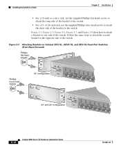
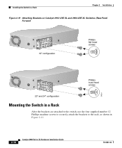
... XL, 2924C XL, and 2924 XL Fixed-Port Switches (Front-Panel Forward) Phillips flat-head screws Phillips truss-head screws 19" configuration MODE 1X 2X 3X 4X 5X 6X 7X 47738 23" and 24" configuration MODE 1X 2X 3X 4X 5X 6X 7X 2-12 Catalyst 2900 Series XL Hardware Installation Guide 78-6461...-04 Installing the Switch in a Rack Chapter 2 Installation • For a 19-inch or a telco rack, use the supplied Phillips truss-head screws to...
... XL, 2924C XL, and 2924 XL Fixed-Port Switches (Front-Panel Forward) Phillips flat-head screws Phillips truss-head screws 19" configuration MODE 1X 2X 3X 4X 5X 6X 7X 47738 23" and 24" configuration MODE 1X 2X 3X 4X 5X 6X 7X 2-12 Catalyst 2900 Series XL Hardware Installation Guide 78-6461...-04 Installing the Switch in a Rack Chapter 2 Installation • For a 19-inch or a telco rack, use the supplied Phillips truss-head screws to...

Hardware Installation Guide
Page 57
Chapter 2 Installation Installing the Switch in a Rack Figure 2-5 Attaching Brackets on Catalyst 2912MF XL, 2924M XL, and 2924M XL DC Modular Switches (Front-Panel Forward) Phillips flat-head screws 19" configuration Phillips truss-head screws 12 MODE 1X 2X 3X 4X 5X 6X 7X 23" and 24" configuration 12 MODE 1X 2X 3X 4X 5X 6X 7X 47297 78-6461-04 Catalyst 2900 Series XL Hardware Installation Guide 2-13
Chapter 2 Installation Installing the Switch in a Rack Figure 2-5 Attaching Brackets on Catalyst 2912MF XL, 2924M XL, and 2924M XL DC Modular Switches (Front-Panel Forward) Phillips flat-head screws 19" configuration Phillips truss-head screws 12 MODE 1X 2X 3X 4X 5X 6X 7X 23" and 24" configuration 12 MODE 1X 2X 3X 4X 5X 6X 7X 47297 78-6461-04 Catalyst 2900 Series XL Hardware Installation Guide 2-13
Hardware Installation Guide
Page 62
Installing the Switch in a Rack Chapter 2 Installation Figure 2-10 Attaching Brackets on Catalyst 2912 LRE XL and 2924 LRE XL Switches (Rear-Panel Forward 19" configuration Phillips flat-head screws 54824 Phillips truss-head screws 23" and 24" configuration Mounting the Switch in a Rack After the brackets are attached to the switch, use the four supplied number-12 Phillips machine screws to securely attach the brackets to the rack, as shown in Figure 2-11. 2-18 Catalyst 2900 Series XL Hardware Installation Guide 78-6461-04
Installing the Switch in a Rack Chapter 2 Installation Figure 2-10 Attaching Brackets on Catalyst 2912 LRE XL and 2924 LRE XL Switches (Rear-Panel Forward 19" configuration Phillips flat-head screws 54824 Phillips truss-head screws 23" and 24" configuration Mounting the Switch in a Rack After the brackets are attached to the switch, use the four supplied number-12 Phillips machine screws to securely attach the brackets to the rack, as shown in Figure 2-11. 2-18 Catalyst 2900 Series XL Hardware Installation Guide 78-6461-04
Hardware Installation Guide
Page 63
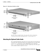
... for the modular switches requires two screws. 78-6461-04 Catalyst 2900 Series XL Hardware Installation Guide 2-19 Attaching the Optional Cable Guide We recommend attaching the cable guide to the left or right bracket. If the switch is mounted in the rack, power the switch as shown in Figure 2-12 to attach the... XL 22X 23X 24X Phillips machine screws 47301 12 MODE 1X 2X 3X Catalyst 2900 SERIES XL 4X 5X 6X 7X 8X 9X 100BaseFX 10X 11X 12X 13X 14X 15X 16X 17X 18X 19X 20X 21X 22X 23X 24X Phillips machine screws After the switch is in a 19-, 23-, or 24-inch ...
... for the modular switches requires two screws. 78-6461-04 Catalyst 2900 Series XL Hardware Installation Guide 2-19 Attaching the Optional Cable Guide We recommend attaching the cable guide to the left or right bracket. If the switch is mounted in the rack, power the switch as shown in Figure 2-12 to attach the... XL 22X 23X 24X Phillips machine screws 47301 12 MODE 1X 2X 3X Catalyst 2900 SERIES XL 4X 5X 6X 7X 8X 9X 100BaseFX 10X 11X 12X 13X 14X 15X 16X 17X 18X 19X 20X 21X 22X 23X 24X Phillips machine screws After the switch is in a 19-, 23-, or 24-inch ...

Hardware Installation Guide
Page 64
... 6X 7X 8X 9X 10X 10BaseT/100Ba1s0e0TBXaseFX 11X 12X 13X 14X Cable guide screw 16X 17X 18X 19X 20X 21X Catalyst 2900 SERIES XL 22X 23X 24X 47302 12 MODE 1X 2X 3X Catalyst 2900 SERIES XL 4X 5X 6X 7X 8X 9X 100BaseFX 10X 11X 12X 13X 14X 15X 16X 17X 18X... 19X 20X 21X 22X 23X 24X Black Philips machine screw Installing the Switch on a Wall Chapter 2 Installation Note The cable guide does...
... 6X 7X 8X 9X 10X 10BaseT/100Ba1s0e0TBXaseFX 11X 12X 13X 14X Cable guide screw 16X 17X 18X 19X 20X 21X Catalyst 2900 SERIES XL 22X 23X 24X 47302 12 MODE 1X 2X 3X Catalyst 2900 SERIES XL 4X 5X 6X 7X 8X 9X 100BaseFX 10X 11X 12X 13X 14X 15X 16X 17X 18X... 19X 20X 21X 22X 23X 24X Black Philips machine screw Installing the Switch on a Wall Chapter 2 Installation Note The cable guide does...

Hardware Installation Guide
Page 70
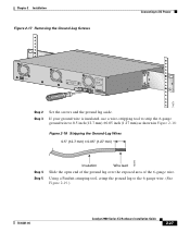
Make sure to earth ground. and 12- Ensure that the host is intended to be made first and disconnected last. Connecting to DC Power Chapter 2 Installation • Four leads of the switch. (See Figure 2-17. 2-26 Catalyst 2900 Series XL Hardware Installation Guide 78-6461-04 or 14-gauge copper wire... earth ground during normal use. or 14-gauge wires Grounding the Switch Warning This equipment is connected to remove the two number-10-16 ground-lug screws and the ground lug from the rear panel of 12- Warning When installing the unit, the ground connection must always be...
Make sure to earth ground. and 12- Ensure that the host is intended to be made first and disconnected last. Connecting to DC Power Chapter 2 Installation • Four leads of the switch. (See Figure 2-17. 2-26 Catalyst 2900 Series XL Hardware Installation Guide 78-6461-04 or 14-gauge copper wire... earth ground during normal use. or 14-gauge wires Grounding the Switch Warning This equipment is connected to remove the two number-10-16 ground-lug screws and the ground lug from the rear panel of 12- Warning When installing the unit, the ground connection must always be...
Hardware Installation Guide
Page 71
... strip the 6-gauge ground wire to the 6-gauge wire. (See Figure 2-19.) 78-6461-04 Catalyst 2900 Series XL Hardware Installation Guide 2-27 Using a Panduit crimping tool, crimp the ground lug to 0.5 inch (12.7 mm) ±0.05 inch (1.27 mm) as shown in Figure 2-18: Figure 2-18 Stripping ...the Ground-Lug Wires 0.5" (12.7 mm) ± 0.05" (1.27 mm) 74076 Step 4 Step 5 Insulation Wire lead Slide the...
... strip the 6-gauge ground wire to the 6-gauge wire. (See Figure 2-19.) 78-6461-04 Catalyst 2900 Series XL Hardware Installation Guide 2-27 Using a Panduit crimping tool, crimp the ground lug to 0.5 inch (12.7 mm) ±0.05 inch (1.27 mm) as shown in Figure 2-18: Figure 2-18 Stripping ...the Ground-Lug Wires 0.5" (12.7 mm) ± 0.05" (1.27 mm) 74076 Step 4 Step 5 Insulation Wire lead Slide the...

Hardware Installation Guide
Page 75
Chapter 2 Installation Figure 2-22 Positive and Negative Positions on the Switch Rear Panel Connecting to 0.27 inch (6.86 mm) ± 0.05 inch (1.27 mm). (See Figure 2-23.) Do not strip more ... the recommended amount of wire can conduct harmful levels of the four wires coming from the terminal block plug. 78-6461-04 Catalyst 2900 Series XL Hardware Installation Guide 2-31 or 14-gauge wire-stripping tool, strip each of electricity. Be sure that you ...four DC-input power source wires into the terminal block plug. Step 3 Positive and negative feed positions Using a 12-
Chapter 2 Installation Figure 2-22 Positive and Negative Positions on the Switch Rear Panel Connecting to 0.27 inch (6.86 mm) ± 0.05 inch (1.27 mm). (See Figure 2-23.) Do not strip more ... the recommended amount of wire can conduct harmful levels of the four wires coming from the terminal block plug. 78-6461-04 Catalyst 2900 Series XL Hardware Installation Guide 2-31 or 14-gauge wire-stripping tool, strip each of electricity. Be sure that you ...four DC-input power source wires into the terminal block plug. Step 3 Positive and negative feed positions Using a 12-
Hardware Installation Guide
Page 82
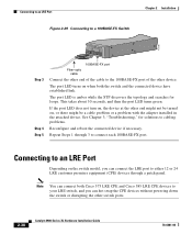
... turns on when both Cisco 575 LRE CPE and Cisco 585 LRE CPE devices to your LRE switch, and you can connect the LRE port to either 12 or 24 LRE customer premises equipment (CPE) devices through 3 to an LRE Port Depending on , the device at the other switch ports. 2-38 Catalyst 2900 Series XL Hardware...
... turns on when both Cisco 575 LRE CPE and Cisco 585 LRE CPE devices to your LRE switch, and you can connect the LRE port to either 12 or 24 LRE customer premises equipment (CPE) devices through 3 to an LRE Port Depending on , the device at the other switch ports. 2-38 Catalyst 2900 Series XL Hardware...
