Hardware Installation Guide
Page 7
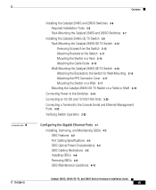
... Connecting a Terminal to the Console Serial and Ethernet Management Ports 3-22 Verifying Switch Operation 3-23 Configuring the Gigabit Ethernet Ports 4-1 Installing, Removing, and Maintaining GBICs 4-2 GBIC Features 4-2 Port Cabling Specifications 4-4 GBIC Optical Power Characteristics 4-5 GBIC Cabling Restrictions 4-5 Installing GBICs 4-6 Removing GBICs 4-9 GBIC Maintenance Guidelines 4-10 Catalyst 2984G, 2948G-GE-TX, and 2980G Switch Hardware Installation Guide vii
... Connecting a Terminal to the Console Serial and Ethernet Management Ports 3-22 Verifying Switch Operation 3-23 Configuring the Gigabit Ethernet Ports 4-1 Installing, Removing, and Maintaining GBICs 4-2 GBIC Features 4-2 Port Cabling Specifications 4-4 GBIC Optical Power Characteristics 4-5 GBIC Cabling Restrictions 4-5 Installing GBICs 4-6 Removing GBICs 4-9 GBIC Maintenance Guidelines 4-10 Catalyst 2984G, 2948G-GE-TX, and 2980G Switch Hardware Installation Guide vii
Hardware Installation Guide
Page 8
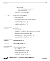
... to the System Component Level 5-2 Identifying Startup Problems 5-3 Troubleshooting the Power Supply 5-4 Contacting Customer Service 5-5 A A P P E N D I X Specifications A-1 Console Serial Port A-1 10BASE-T and 10/100BASE-T Ethernet Management Ports A-2 Catalyst 2948G Switch Specifications A-2 Catalyst 2948G-GE-TX Switch Specifications A-5 Catalyst 2980G Switch Specifications A-6 B A P P E N D I X Repacking a Switch B-1 C A P P E N D I X Differential Mode Delay C-1 D A P P E N D I X Translated Safety Warnings D-1 Warning Definition D-2 Safety Information Referral Warning D-7 Qualified...
... to the System Component Level 5-2 Identifying Startup Problems 5-3 Troubleshooting the Power Supply 5-4 Contacting Customer Service 5-5 A A P P E N D I X Specifications A-1 Console Serial Port A-1 10BASE-T and 10/100BASE-T Ethernet Management Ports A-2 Catalyst 2948G Switch Specifications A-2 Catalyst 2948G-GE-TX Switch Specifications A-5 Catalyst 2980G Switch Specifications A-6 B A P P E N D I X Repacking a Switch B-1 C A P P E N D I X Differential Mode Delay C-1 D A P P E N D I X Translated Safety Warnings D-1 Warning Definition D-2 Safety Information Referral Warning D-7 Qualified...
Hardware Installation Guide
Page 16
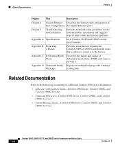
..., Catalyst 2948G, and Catalyst 2980G Switches Catalyst 2984G, 2948G-GE-TX, and 2980G Switch Hardware Installation Guide xvi 78-6286-05 Appendix B Repacking a Switch Provides procedures to repack your Catalyst 2948G or 2980G switch in this guide. Related Documentation Refer to the following documents for the initial hardware installation and suggests steps to help isolate and resolve problems. Appendix A Specifications Lists Catalyst 2948G and 2980G switch specifications. Related...
..., Catalyst 2948G, and Catalyst 2980G Switches Catalyst 2984G, 2948G-GE-TX, and 2980G Switch Hardware Installation Guide xvi 78-6286-05 Appendix B Repacking a Switch Provides procedures to repack your Catalyst 2948G or 2980G switch in this guide. Related Documentation Refer to the following documents for the initial hardware installation and suggests steps to help isolate and resolve problems. Appendix A Specifications Lists Catalyst 2948G and 2980G switch specifications. Related...

Hardware Installation Guide
Page 37
A test other end. 78-6286-05 Catalyst 2984G, 2948G-GE-TX, and 2980G Switch Hardware Installation Guide 1-9 Port is operational. No signal detected, or link configuration failure. Power supply is disabled by user. Power supply has failed or is operational. Airflow Note For environmental specifications, see Chapter 2, "Site Planning." All tests pass. Indicates the link status of...
A test other end. 78-6286-05 Catalyst 2984G, 2948G-GE-TX, and 2980G Switch Hardware Installation Guide 1-9 Port is operational. No signal detected, or link configuration failure. Power supply is disabled by user. Power supply has failed or is operational. Airflow Note For environmental specifications, see Chapter 2, "Site Planning." All tests pass. Indicates the link status of...
Hardware Installation Guide
Page 39
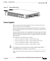
... power supply-Catalyst 2948G switch • 156 W AC internal power supply-Catalyst 2948G-GE-TX switch • 175 W AC internal power supply-Catalyst 2980G switch • 156 W AC internal power supply-Catalyst 2980G-A switch Note For complete power specifications for the Catalyst 2948G, 2948G-GE-TX, and 2980G switches, see Appendix A, "Specifications." These switches also be used with an optional Cisco Redundant Power System (RPS). 78-6286-05 Catalyst 2984G, 2948G-GE-TX, and 2980G Switch Hardware...
... power supply-Catalyst 2948G switch • 156 W AC internal power supply-Catalyst 2948G-GE-TX switch • 175 W AC internal power supply-Catalyst 2980G switch • 156 W AC internal power supply-Catalyst 2980G-A switch Note For complete power specifications for the Catalyst 2948G, 2948G-GE-TX, and 2980G switches, see Appendix A, "Specifications." These switches also be used with an optional Cisco Redundant Power System (RPS). 78-6286-05 Catalyst 2984G, 2948G-GE-TX, and 2980G Switch Hardware...
Hardware Installation Guide
Page 44
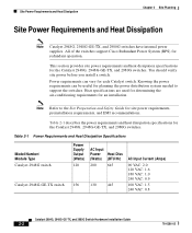
All of the switches support Cisco Redundant Power System (RPS) for planning the power distribution system needed to the Site Preparation and Safety Guide for an installation. Knowing the power requirements can vary for the Catalyst 2948G, 2948G-GE-TX, and 2980G switches. Table 2-1 Power Requirements and Heat Dissipation Specifications Model Number/ Module Type Catalyst 2948G switch Catalyst 2948G-GE-TX switch Power Supply Output (Watts) 120 156...
All of the switches support Cisco Redundant Power System (RPS) for planning the power distribution system needed to the Site Preparation and Safety Guide for an installation. Knowing the power requirements can vary for the Catalyst 2948G, 2948G-GE-TX, and 2980G switches. Table 2-1 Power Requirements and Heat Dissipation Specifications Model Number/ Module Type Catalyst 2948G switch Catalyst 2948G-GE-TX switch Power Supply Output (Watts) 120 156...

Hardware Installation Guide
Page 45
Note These guidelines do not apply to the Catalyst 2948G-GE-TX switches. Chapter 2 Site Planning System Ground Connection Guidelines (Catalyst 2948G and 2980G Switches Only) Table 2-1 Power Requirements and Heat Dissipation Specifications (continued) Model Number/ Module Type Catalyst 2980G switch Catalyst 2980G-A switch Power Supply Output (Watts) 175 156 AC Input Power Heat Diss (Watts) (BTU/Hr) 300 950 208 670 AC Input...
Note These guidelines do not apply to the Catalyst 2948G-GE-TX switches. Chapter 2 Site Planning System Ground Connection Guidelines (Catalyst 2948G and 2980G Switches Only) Table 2-1 Power Requirements and Heat Dissipation Specifications (continued) Model Number/ Module Type Catalyst 2980G switch Catalyst 2980G-A switch Power Supply Output (Watts) 175 156 AC Input Power Heat Diss (Watts) (BTU/Hr) 300 950 208 670 AC Input...
Hardware Installation Guide
Page 52
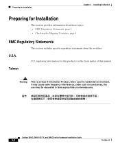
... information about these topics: • EMC Regulatory Statements, page 2 • Checking the Shipping Container, page 4 EMC Regulatory Statements This section includes specific regulatory statements about the switches. U.S. Catalyst 2984G, 2948G-GE-TX, and 2980G Switch Hardware Installation Guide 3-2 78-6286-05 U.S.A. Taiwan Warning This is in residential environment, it may cause radio frequency interference, under such circumstances...
... information about these topics: • EMC Regulatory Statements, page 2 • Checking the Shipping Container, page 4 EMC Regulatory Statements This section includes specific regulatory statements about the switches. U.S. Catalyst 2984G, 2948G-GE-TX, and 2980G Switch Hardware Installation Guide 3-2 78-6286-05 U.S.A. Taiwan Warning This is in residential environment, it may cause radio frequency interference, under such circumstances...

Hardware Installation Guide
Page 71
... connect the switch to 10BASE-T, 100BASE-TX, or 1000BASE-T devices, follow these steps: Step 1 When connecting to servers, workstations, and routers, insert a twisted-pair straight-through cable in a front-panel RJ-45 connector, as shown in an RJ-45 connector on the target device. 78-6286-05 Catalyst 2984G, 2948G-GE-TX, and 2980G Switch Hardware Installation...
... connect the switch to 10BASE-T, 100BASE-TX, or 1000BASE-T devices, follow these steps: Step 1 When connecting to servers, workstations, and routers, insert a twisted-pair straight-through cable in a front-panel RJ-45 connector, as shown in an RJ-45 connector on the target device. 78-6286-05 Catalyst 2984G, 2948G-GE-TX, and 2980G Switch Hardware Installation...
Hardware Installation Guide
Page 72
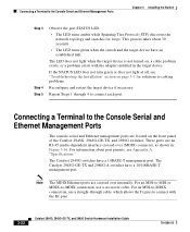
...does not light at all, see Appendix A, "Specifications." Connecting a Terminal to connect with the adapter installed in Figure 3-16. The Catalyst 2948G-GE-TX and 2980G-A switches have a 10BASE-T management port. Repeat Steps 1 through cable, which allows the Tx pins to the Console Serial and Ethernet Management ...MDIX Ethernet ports are located on , a cable problem exists, or a problem exists with the Rx pins. 3-22 Catalyst 2984G, 2948G-GE-TX, and 2980G Switch Hardware Installation Guide 78-6286-05 The LED does not light when the target device is not turned on the front panel...
...does not light at all, see Appendix A, "Specifications." Connecting a Terminal to connect with the adapter installed in Figure 3-16. The Catalyst 2948G-GE-TX and 2980G-A switches have a 10BASE-T management port. Repeat Steps 1 through cable, which allows the Tx pins to the Console Serial and Ethernet Management ...MDIX Ethernet ports are located on , a cable problem exists, or a problem exists with the Rx pins. 3-22 Catalyst 2984G, 2948G-GE-TX, and 2980G Switch Hardware Installation Guide 78-6286-05 The LED does not light when the target device is not turned on the front panel...

Hardware Installation Guide
Page 76
... port when no cable is connected, avoid exposure to install, remove, and maintain them: • GBIC Features, page 4-2 • Port Cabling Specifications, page 4-4 • GBIC Optical Power Characteristics, page 4-5 • GBIC Cabling Restrictions, page 4-5 • Installing GBICs, page 4-6 •...Features Warning Because invisible laser radiation may be emitted from the aperture of GBICs in the Gigabit Ethernet switching module. Catalyst 2984G, 2948G-GE-TX, and 2980G Switch Hardware Installation Guide 4-2 78-6286-05 Statement 70 GBICs (see Figure 4-1) are hot-swappable input/...
... port when no cable is connected, avoid exposure to install, remove, and maintain them: • GBIC Features, page 4-2 • Port Cabling Specifications, page 4-4 • GBIC Optical Power Characteristics, page 4-5 • GBIC Cabling Restrictions, page 4-5 • Installing GBICs, page 4-6 •...Features Warning Because invisible laser radiation may be emitted from the aperture of GBICs in the Gigabit Ethernet switching module. Catalyst 2984G, 2948G-GE-TX, and 2980G Switch Hardware Installation Guide 4-2 78-6286-05 Statement 70 GBICs (see Figure 4-1) are hot-swappable input/...
Hardware Installation Guide
Page 78
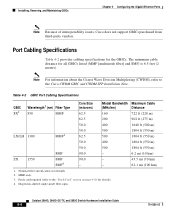
SMF4 - - 43.5 mi (70 km) 62.1 mi (100 km) 1. Table 4-2 GBIC Port Cabling Specifications GBIC SX2 Wavelength1 (nm) Fiber Type 850 MMF Core Size (microns) 62.5 Modal Bandwidth Maximum Cable (MHz/km) Distance 160 722 ft (220...9/10 - 6.2 mi (10 km) ZX 1550 SMF 9/10 - Patch cord required (refer to the Cisco CWDM GBIC and CWDM SFP Installation Note. The minimum cable distance for the GBICs. Catalyst 2984G, 2948G-GE-TX, and 2980G Switch Hardware Installation Guide 4-4 78-6286-05 Installing, Removing, and Maintaining GBICs Chapter 4 Configuring the Gigabit Ethernet Ports...
SMF4 - - 43.5 mi (70 km) 62.1 mi (100 km) 1. Table 4-2 GBIC Port Cabling Specifications GBIC SX2 Wavelength1 (nm) Fiber Type 850 MMF Core Size (microns) 62.5 Modal Bandwidth Maximum Cable (MHz/km) Distance 160 722 ft (220...9/10 - 6.2 mi (10 km) ZX 1550 SMF 9/10 - Patch cord required (refer to the Cisco CWDM GBIC and CWDM SFP Installation Note. The minimum cable distance for the GBICs. Catalyst 2984G, 2948G-GE-TX, and 2980G Switch Hardware Installation Guide 4-4 78-6286-05 Installing, Removing, and Maintaining GBICs Chapter 4 Configuring the Gigabit Ethernet Ports...

Hardware Installation Guide
Page 85
.... 78-6286-05 Catalyst 2984G, 2948G-GE-TX, and 2980G Switch Hardware Installation Guide 4-11 Note Cisco Gigabit Ethernet products have been tested and evaluated to Appendix C, "Differential Mode Delay." Plug the end labeled "To cable plant" into the GBIC (see Figure 4-6). The patch cord is compliant with the standards listed in Appendix A, "Specifications." For a detailed description...
.... 78-6286-05 Catalyst 2984G, 2948G-GE-TX, and 2980G Switch Hardware Installation Guide 4-11 Note Cisco Gigabit Ethernet products have been tested and evaluated to Appendix C, "Differential Mode Delay." Plug the end labeled "To cable plant" into the GBIC (see Figure 4-6). The patch cord is compliant with the standards listed in Appendix A, "Specifications." For a detailed description...

Hardware Installation Guide
Page 87
...Category 5 cable. A mode-conditioning patch cord is used to 100 km by using the LX/LH SFP module with security information. Use only Cisco SFP modules on both the sending and receiving ends of the link. Chapter 4 Configuring the Gigabit Ethernet Ports Connecting To an SFP Module The ...restrictions are that each port must match the wave-length specifications on the other end of the cable, and the cable must also install a mode-conditioning patch cord between the SFP module and the MMF cable on the Catalyst 2948G-GE-TX switch. the distance depends on the fiber quality, the ...
...Category 5 cable. A mode-conditioning patch cord is used to 100 km by using the LX/LH SFP module with security information. Use only Cisco SFP modules on both the sending and receiving ends of the link. Chapter 4 Configuring the Gigabit Ethernet Ports Connecting To an SFP Module The ...restrictions are that each port must match the wave-length specifications on the other end of the cable, and the cable must also install a mode-conditioning patch cord between the SFP module and the MMF cable on the Catalyst 2948G-GE-TX switch. the distance depends on the fiber quality, the ...

Hardware Installation Guide
Page 88
...the port and cabling stipulations in Figure 4-7. 4-14 Catalyst 2984G, 2948G-GE-TX, and 2980G Switch Hardware Installation Guide 78-6286-05 Insert one end of the fiber-optic cable into beams or view directly with optical instruments. See Appendix A, "Specifications," for fiber-optic connections. Caution Do not remove... cable. Follow these SFP modules, refer to your SFP module documentation and to the Cisco Small Form-Factor Pluggable Modules Installation Notes (not orderable but is available on Cisco.com.) For the latest information about the LC on fiber-optic SFP modules or the...
...the port and cabling stipulations in Figure 4-7. 4-14 Catalyst 2984G, 2948G-GE-TX, and 2980G Switch Hardware Installation Guide 78-6286-05 Insert one end of the fiber-optic cable into beams or view directly with optical instruments. See Appendix A, "Specifications," for fiber-optic connections. Caution Do not remove... cable. Follow these SFP modules, refer to your SFP module documentation and to the Cisco Small Form-Factor Pluggable Modules Installation Notes (not orderable but is available on Cisco.com.) For the latest information about the LC on fiber-optic SFP modules or the...
Hardware Installation Guide
Page 92
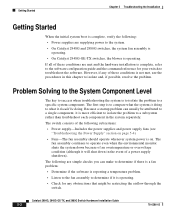
The first step is to compare what the system is doing . The switch consists of an overtemperature or overvoltage condition (although it is more efficient to isolate the problem to a specific system component. The fan assembly continues to what it should operate whenever ...is complete, refer to the software configuration guide and the command reference for your switch to the system. • On Catalyst 2948G and 2980G switches, the system fan assembly is operating. • On Catalyst 2948G-GE-TX switches, the blower is operating. • Check for any obstructions that might be ...
The first step is to compare what the system is doing . The switch consists of an overtemperature or overvoltage condition (although it is more efficient to isolate the problem to a specific system component. The fan assembly continues to what it should operate whenever ...is complete, refer to the software configuration guide and the command reference for your switch to the system. • On Catalyst 2948G and 2980G switches, the system fan assembly is operating. • On Catalyst 2948G-GE-TX switches, the blower is operating. • Check for any obstructions that might be ...

Hardware Installation Guide
Page 97
.... Table A-1 Console Port Pinouts Pin Signal 1 RTS 2 DTR 3 TXD 4 GND 5 GND 6 RXD 7 DSR 8 CTS Direction output output output Description request to send 78-6286-05 Catalyst 2984G, 2948G-GE-TX, and 2980G Switch Hardware Installation Guide A-1 A A P P E N D I X Specifications This appendix provides management port and technical specifications for the Catalyst 2948G, 2948G-GE-TX, and 2980G...
.... Table A-1 Console Port Pinouts Pin Signal 1 RTS 2 DTR 3 TXD 4 GND 5 GND 6 RXD 7 DSR 8 CTS Direction output output output Description request to send 78-6286-05 Catalyst 2984G, 2948G-GE-TX, and 2980G Switch Hardware Installation Guide A-1 A A P P E N D I X Specifications This appendix provides management port and technical specifications for the Catalyst 2948G, 2948G-GE-TX, and 2980G...

Hardware Installation Guide
Page 98
... receptacle with a Link Status LED. Table A-3 Catalyst 2948G Switch Specifications Item Environmental Temperature, ambient operating Temperature, ambient nonoperating and storage Humidity (RH), ambient (noncondensing) operating Specification 32°F (0°C) to 104°F (40°C) -40°F (-40°C) to 167°F (75°C) 10% to 90% Catalyst 2984G, 2948G-GE-TX, and 2980G Switch Hardware Installation Guide A-2 78-6286-05
... receptacle with a Link Status LED. Table A-3 Catalyst 2948G Switch Specifications Item Environmental Temperature, ambient operating Temperature, ambient nonoperating and storage Humidity (RH), ambient (noncondensing) operating Specification 32°F (0°C) to 104°F (40°C) -40°F (-40°C) to 167°F (75°C) 10% to 90% Catalyst 2984G, 2948G-GE-TX, and 2980G Switch Hardware Installation Guide A-2 78-6286-05

Hardware Installation Guide
Page 99
...Specifications Catalyst 2948G Switch Specifications Table A-3 Catalyst 2948G Switch Specifications (continued) Item Environmental (continued) Humidity (RH), ambient (noncondensing) nonoperating and storage Altitude, operating and nonoperating Switching Components Backplane Microprocessor Memory Physical Characteristics Dimensions (H x W x D) Weight AC Power Power supply output System power dissipation System heat dissipation AC input current AC frequency KVA rating Airflow Specification... back side out 78-6286-05 Catalyst 2984G, 2948G-GE-TX, and 2980G Switch Hardware Installation Guide A-3
...Specifications Catalyst 2948G Switch Specifications Table A-3 Catalyst 2948G Switch Specifications (continued) Item Environmental (continued) Humidity (RH), ambient (noncondensing) nonoperating and storage Altitude, operating and nonoperating Switching Components Backplane Microprocessor Memory Physical Characteristics Dimensions (H x W x D) Weight AC Power Power supply output System power dissipation System heat dissipation AC input current AC frequency KVA rating Airflow Specification... back side out 78-6286-05 Catalyst 2984G, 2948G-GE-TX, and 2980G Switch Hardware Installation Guide A-3

Hardware Installation Guide
Page 101
Appendix A Specifications Catalyst 2948G-GE-TX Switch Specifications Catalyst 2948G-GE-TX Switch Specifications Table A-4 lists the Catalyst 2948G-GE-TX specifications. Table A-4 Catalyst 2948G-GE-TX Switch Specifications Item Environmental Temperature, ambient operating Temperature, ambient nonoperating and storage Humidity (RH), ambient (noncondensing) operating Humidity (RH), ambient (noncondensing) nonoperating and storage Altitude, operating and ...
Appendix A Specifications Catalyst 2948G-GE-TX Switch Specifications Catalyst 2948G-GE-TX Switch Specifications Table A-4 lists the Catalyst 2948G-GE-TX specifications. Table A-4 Catalyst 2948G-GE-TX Switch Specifications Item Environmental Temperature, ambient operating Temperature, ambient nonoperating and storage Humidity (RH), ambient (noncondensing) operating Humidity (RH), ambient (noncondensing) nonoperating and storage Altitude, operating and ...
