Hardware Installation Guide
Page 6
... and 10/100/1000 Ports 1-6 Catalyst 2948G and 2980G Switch Ports 1-7 Catalyst 2948G-GE-TX Switch Ports 1-7 Switch Components 1-7 Management Ports 1-8 Console Serial Port 1-8 10BASE-T and 10/100BASE-T Ports 1-8 Front Panel LEDs 1-8 Airflow 1-9 Power Supplies 1-11 2 C H A P T E R Site Planning 2-1 Site Power Requirements and Heat Dissipation 2-2 System Ground Connection Guidelines (Catalyst 2948G and 2980G Switches Only) 2-3 Connecting the Switch to Earth Ground 2-5 Site-Planning...
... and 10/100/1000 Ports 1-6 Catalyst 2948G and 2980G Switch Ports 1-7 Catalyst 2948G-GE-TX Switch Ports 1-7 Switch Components 1-7 Management Ports 1-8 Console Serial Port 1-8 10BASE-T and 10/100BASE-T Ports 1-8 Front Panel LEDs 1-8 Airflow 1-9 Power Supplies 1-11 2 C H A P T E R Site Planning 2-1 Site Power Requirements and Heat Dissipation 2-2 System Ground Connection Guidelines (Catalyst 2948G and 2980G Switches Only) 2-3 Connecting the Switch to Earth Ground 2-5 Site-Planning...
Hardware Installation Guide
Page 7
... RPS Connector Cover 3-17 Mounting the Switch on a Wall 3-17 Mounting the Catalyst 2948G-GE-TX Switch on a Table or Shelf 3-19 Connecting Power to the Switches 3-19 Connecting to 10/100 and 10/100/1000 Ports 3-20 Connecting a Terminal to the Console Serial and Ethernet Management Ports 3-22 Verifying Switch Operation 3-23 Configuring the Gigabit Ethernet...
... RPS Connector Cover 3-17 Mounting the Switch on a Wall 3-17 Mounting the Catalyst 2948G-GE-TX Switch on a Table or Shelf 3-19 Connecting Power to the Switches 3-19 Connecting to 10/100 and 10/100/1000 Ports 3-20 Connecting a Terminal to the Console Serial and Ethernet Management Ports 3-22 Verifying Switch Operation 3-23 Configuring the Gigabit Ethernet...
Hardware Installation Guide
Page 8
... to the System Component Level 5-2 Identifying Startup Problems 5-3 Troubleshooting the Power Supply 5-4 Contacting Customer Service 5-5 A A P P E N D I X Specifications A-1 Console Serial Port A-1 10BASE-T and 10/100BASE-T Ethernet Management Ports A-2 Catalyst 2948G Switch Specifications A-2 Catalyst 2948G-GE-TX Switch Specifications A-5 Catalyst 2980G Switch Specifications A-6 B A P P E N D I X Repacking a Switch B-1 C A P P E N D I X Differential Mode Delay C-1 D A P P E N D I X Translated Safety Warnings D-1 Warning Definition D-2 Safety Information Referral Warning D-7 Qualified...
... to the System Component Level 5-2 Identifying Startup Problems 5-3 Troubleshooting the Power Supply 5-4 Contacting Customer Service 5-5 A A P P E N D I X Specifications A-1 Console Serial Port A-1 10BASE-T and 10/100BASE-T Ethernet Management Ports A-2 Catalyst 2948G Switch Specifications A-2 Catalyst 2948G-GE-TX Switch Specifications A-5 Catalyst 2980G Switch Specifications A-6 B A P P E N D I X Repacking a Switch B-1 C A P P E N D I X Differential Mode Delay C-1 D A P P E N D I X Translated Safety Warnings D-1 Warning Definition D-2 Safety Information Referral Warning D-7 Qualified...
Hardware Installation Guide
Page 30
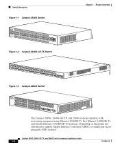
Switch Description Figure 1-1 Catalyst 2948G Switch STATUS Catalyst 2948G CONSOLE 1000Base - Catalyst 2984G, 2948G-GE-TX, and 2980G Switch Hardware Installation Guide 1-2 78-6286-05 Depending on the model, the switches also support Gigabit Interface Converters (GBICs) or small form-factor pluggable (SFP) modules. X 10BaseT Figure 1-2 Catalyst 2948G-GE-TX Switch 98431 Chapter 1 Product Overview 98434 Figure 1-3 Catalyst 2980G Switch 50747 1 2 STATUS 10/100/1000 ETHERENET 1 1 2 3 4 2 1 2 3 4 56...
Switch Description Figure 1-1 Catalyst 2948G Switch STATUS Catalyst 2948G CONSOLE 1000Base - Catalyst 2984G, 2948G-GE-TX, and 2980G Switch Hardware Installation Guide 1-2 78-6286-05 Depending on the model, the switches also support Gigabit Interface Converters (GBICs) or small form-factor pluggable (SFP) modules. X 10BaseT Figure 1-2 Catalyst 2948G-GE-TX Switch 98431 Chapter 1 Product Overview 98434 Figure 1-3 Catalyst 2980G Switch 50747 1 2 STATUS 10/100/1000 ETHERENET 1 1 2 3 4 2 1 2 3 4 56...
Hardware Installation Guide
Page 33
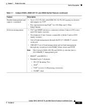
... of new features compatible with the Catalyst 6500 family switches • Out-of-band management through the RJ-45 10BASE-T console serial port • 10BASE-T out-of-band management and in-band management through any switch port with SNMP, Telnet client, and TFTP Note The Catalyst 2948G-GE-TX and 2980G-A switches have a 10/100BASE-T management port...
... of new features compatible with the Catalyst 6500 family switches • Out-of-band management through the RJ-45 10BASE-T console serial port • 10BASE-T out-of-band management and in-band management through any switch port with SNMP, Telnet client, and TFTP Note The Catalyst 2948G-GE-TX and 2980G-A switches have a 10/100BASE-T management port...
Hardware Installation Guide
Page 36
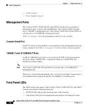
... is not for network management only; Front Panel LEDs The LEDs on the front panels of the Catalyst 2948G, 2948G-GE-TX, and 2980G switches perform the following functions: • STATUS LEDs indicate the operating state of management ports: console serial and Ethernet. This port is not available between this port and the 10/100BASE...
... is not for network management only; Front Panel LEDs The LEDs on the front panels of the Catalyst 2948G, 2948G-GE-TX, and 2980G switches perform the following functions: • STATUS LEDs indicate the operating state of management ports: console serial and Ethernet. This port is not available between this port and the 10/100BASE...
Hardware Installation Guide
Page 38
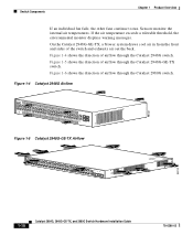
... draws cool air in from the front and sides of airflow through the Catalyst 2948G-GE-TX switch. Sensors monitor the internal air temperatures. Figure 1-5 shows the direction of the switch and exhausts air out the back. Figure 1-4 Catalyst 2948G Airflow 98432 STATUS Catalyst 2948G CONSOLE 1000Base - Switch Components Chapter 1 Product Overview If an individual fan fails, the other fans...
... draws cool air in from the front and sides of airflow through the Catalyst 2948G-GE-TX switch. Sensors monitor the internal air temperatures. Figure 1-5 shows the direction of the switch and exhausts air out the back. Figure 1-4 Catalyst 2948G Airflow 98432 STATUS Catalyst 2948G CONSOLE 1000Base - Switch Components Chapter 1 Product Overview If an individual fan fails, the other fans...
Hardware Installation Guide
Page 39
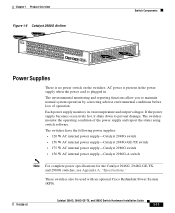
... internal power supply-Catalyst 2948G switch • 156 W AC internal power supply-Catalyst 2948G-GE-TX switch • 175 W AC internal power supply-Catalyst 2980G switch • 156 W AC internal power supply-Catalyst 2980G-A switch Note For complete power specifications for the Catalyst 2948G, 2948G-GE-TX, and 2980G switches, see Appendix A, "Specifications." These switches also be used with an optional Cisco Redundant Power System (RPS...
... internal power supply-Catalyst 2948G switch • 156 W AC internal power supply-Catalyst 2948G-GE-TX switch • 175 W AC internal power supply-Catalyst 2980G switch • 156 W AC internal power supply-Catalyst 2980G-A switch Note For complete power specifications for the Catalyst 2948G, 2948G-GE-TX, and 2980G switches, see Appendix A, "Specifications." These switches also be used with an optional Cisco Redundant Power System (RPS...
Hardware Installation Guide
Page 51
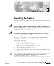
...: • Preparing for Installation, page 2 • Installing the Catalyst 2948G and 2980G Switches, page 6 • Installing the Catalyst 2948G-GE-TX Switch, page 9 • Connecting Power to the Switches, page 19 • Connecting a Terminal to install the Catalyst 2948G, 2948G-GE-TX, and 2980G switches. Statement 1030 This chapter describes how to the Console Serial and Ethernet Management Ports, page 22 Note...
...: • Preparing for Installation, page 2 • Installing the Catalyst 2948G and 2980G Switches, page 6 • Installing the Catalyst 2948G-GE-TX Switch, page 9 • Connecting Power to the Switches, page 19 • Connecting a Terminal to install the Catalyst 2948G, 2948G-GE-TX, and 2980G switches. Statement 1030 This chapter describes how to the Console Serial and Ethernet Management Ports, page 22 Note...

Hardware Installation Guide
Page 58
...Brackets 98435 STATUS Catalyst 2948G CONSOLE 1000Base - Install the chassis in the equipment rack. d. The rack-mounting procedure for the Catalyst 2980G switch is shown in the front of the rack, insert the rear of the rack. b. Catalyst 2984G, 2948G-GE-TX, and 2980G Switch Hardware Installation Guide ... the threaded holes in the front of the chassis between the mounting posts. Installing the Catalyst 2948G and 2980G Switches Chapter 3 Installing the Switch The L brackets connect the switch chassis to the rack. X 10BaseT Step 3 Figure 3-2 shows how to attach the ...
...Brackets 98435 STATUS Catalyst 2948G CONSOLE 1000Base - Install the chassis in the equipment rack. d. The rack-mounting procedure for the Catalyst 2980G switch is shown in the front of the rack, insert the rear of the rack. b. Catalyst 2984G, 2948G-GE-TX, and 2980G Switch Hardware Installation Guide ... the threaded holes in the front of the chassis between the mounting posts. Installing the Catalyst 2948G and 2980G Switches Chapter 3 Installing the Switch The L brackets connect the switch chassis to the rack. X 10BaseT Step 3 Figure 3-2 shows how to attach the ...

Hardware Installation Guide
Page 59
... following guidelines are provided to ensure that the system remains stable. Statement 1006 78-6286-05 Catalyst 2984G, 2948G-GE-TX, and 2980G Switch Hardware Installation Guide 3-9 X 10BaseT Installing the Catalyst 2948G-GE-TX Switch 98436 Installing the Catalyst 2948G-GE-TX Switch Warning To prevent bodily injury when mounting or servicing this unit in a partially filled rack, load... it is provided with stabilizing devices, install the stabilizers before mounting or servicing the unit in the Rack 17.75 inches (45.09 cm) STATUS Catalyst 2948G CONSOLE 1000Base -
... following guidelines are provided to ensure that the system remains stable. Statement 1006 78-6286-05 Catalyst 2984G, 2948G-GE-TX, and 2980G Switch Hardware Installation Guide 3-9 X 10BaseT Installing the Catalyst 2948G-GE-TX Switch 98436 Installing the Catalyst 2948G-GE-TX Switch Warning To prevent bodily injury when mounting or servicing this unit in a partially filled rack, load... it is provided with stabilizing devices, install the stabilizers before mounting or servicing the unit in the Rack 17.75 inches (45.09 cm) STATUS Catalyst 2948G CONSOLE 1000Base -
Hardware Installation Guide
Page 69
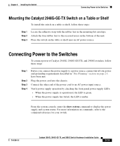
...When the power supply has failed, the LED is amber. From the system console, enter the show system command to the command reference for your switch. 78-6286-05 Catalyst 2984G, 2948G-GE-TX, and 2980G Switch Hardware Installation Guide 3-19 Plug the power cord into the chassis. Place ... all site power and grounding requirements described in the mounting-kit envelope. Chapter 3 Installing the Switch Connecting Power to the Switches Mounting the Catalyst 2948G-GE-TX Switch on a Table or Shelf To install the switch on a table or shelf, follow these steps: Step 1 Step 2 Step 3 Locate the...
...When the power supply has failed, the LED is amber. From the system console, enter the show system command to the command reference for your switch. 78-6286-05 Catalyst 2984G, 2948G-GE-TX, and 2980G Switch Hardware Installation Guide 3-19 Plug the power cord into the chassis. Place ... all site power and grounding requirements described in the mounting-kit envelope. Chapter 3 Installing the Switch Connecting Power to the Switches Mounting the Catalyst 2948G-GE-TX Switch on a Table or Shelf To install the switch on a table or shelf, follow these steps: Step 1 Step 2 Step 3 Locate the...
Hardware Installation Guide
Page 72
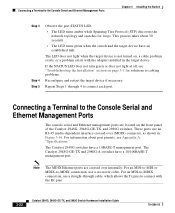
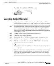
...takes about port pinouts, see "Troubleshooting the Installation" section on the front panel of the Catalyst 2948G, 2948G-GE-TX, and 2980G switches. These ports use a crossover cable. The Catalyst 2948G-GE-TX and 2980G-A switches have a 10BASE-T management port. Connecting a Terminal to -MDIX connection, use an RJ-45... The MDIX Ethernet ports are located on page 5-1 for loops. For an MDI-to-MDI or MDIX-to the Console Serial and Ethernet Management Ports Chapter 3 Installing the Switch Step 3 Step 4 Step 5 Observe the port STATUS LED: • The LED turns amber while Spanning Tree ...
...takes about port pinouts, see "Troubleshooting the Installation" section on the front panel of the Catalyst 2948G, 2948G-GE-TX, and 2980G switches. These ports use a crossover cable. The Catalyst 2948G-GE-TX and 2980G-A switches have a 10BASE-T management port. Connecting a Terminal to -MDIX connection, use an RJ-45... The MDIX Ethernet ports are located on page 5-1 for loops. For an MDI-to-MDI or MDIX-to the Console Serial and Ethernet Management Ports Chapter 3 Installing the Switch Step 3 Step 4 Step 5 Observe the port STATUS LED: • The LED turns amber while Spanning Tree ...
Hardware Installation Guide
Page 73
... do not illuminate until the boot is complete. When the system boot is complete, the console screen displays a script and system banner. 78-6286-05 Catalyst 2984G, 2948G-GE-TX, and 2980G Switch Hardware Installation Guide 3-23 Check the console terminal and make sure that they are operational. During this initialization, the interface LEDs flash...
... do not illuminate until the boot is complete. When the system boot is complete, the console screen displays a script and system banner. 78-6286-05 Catalyst 2984G, 2948G-GE-TX, and 2980G Switch Hardware Installation Guide 3-23 Check the console terminal and make sure that they are operational. During this initialization, the interface LEDs flash...
Hardware Installation Guide
Page 81
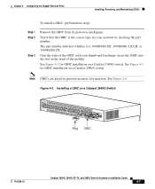
insert the GBIC into the slot on a Catalyst 2980G switch. See Figure 4-4. Verify that the GBIC is 1000BASE-SX, 1000BASE-LX/LH, or 1000BASE-ZX. Note GBICs are keyed to prevent ... by checking the part number. See Figure 4-3 for your thumb and forefinger; X 10BaseT Plug GBIC 78-6286-05 Catalyst 2984G, 2948G-GE-TX, and 2980G Switch Hardware Installation Guide 4-7 See Figure 4-2 for GBIC installation on a Catalyst 2948G Switch 98456 STATUS Catalyst 2948G CONSOLE 1000Base - Figure 4-2 Installing a GBIC on a Catalyst 2948G switch. Grip the sides of the module.
insert the GBIC into the slot on a Catalyst 2980G switch. See Figure 4-4. Verify that the GBIC is 1000BASE-SX, 1000BASE-LX/LH, or 1000BASE-ZX. Note GBICs are keyed to prevent ... by checking the part number. See Figure 4-3 for your thumb and forefinger; X 10BaseT Plug GBIC 78-6286-05 Catalyst 2984G, 2948G-GE-TX, and 2980G Switch Hardware Installation Guide 4-7 See Figure 4-2 for GBIC installation on a Catalyst 2948G Switch 98456 STATUS Catalyst 2948G CONSOLE 1000Base - Figure 4-2 Installing a GBIC on a Catalyst 2948G switch. Grip the sides of the module.
Hardware Installation Guide
Page 82
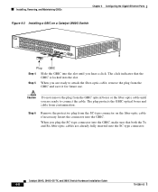
... the GBIC. Insert the connector into the SC-type connector. The plug protects the GBIC optical bores and cable from the SC-type connector on a Catalyst 2980G Switch 1 2 STATUS 10/100/1000 ETHERENET 1 1 2 3 4 2 1 2 3 4 56 78 5 6 7 8 9 10 11 12 13 14 15 16 9 10 11 12 13 14 15 ... 38 39 40 41 42 43 44 45 46 47 48 48 32 33 CONSOLE 10MB MGT 34 PWR RESET 98458 Plug GBIC Step 4 Slide the GBIC into the slot. Catalyst 2984G, 2948G-GE-TX, and 2980G Switch Hardware Installation Guide 4-8 78-6286-05 Installing, Removing, and Maintaining GBICs Chapter ...
... the GBIC. Insert the connector into the SC-type connector. The plug protects the GBIC optical bores and cable from the SC-type connector on a Catalyst 2980G Switch 1 2 STATUS 10/100/1000 ETHERENET 1 1 2 3 4 2 1 2 3 4 56 78 5 6 7 8 9 10 11 12 13 14 15 16 9 10 11 12 13 14 15 ... 38 39 40 41 42 43 44 45 46 47 48 48 32 33 CONSOLE 10MB MGT 34 PWR RESET 98458 Plug GBIC Step 4 Slide the GBIC into the slot. Catalyst 2984G, 2948G-GE-TX, and 2980G Switch Hardware Installation Guide 4-8 78-6286-05 Installing, Removing, and Maintaining GBICs Chapter ...
Hardware Installation Guide
Page 94
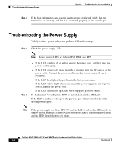
...Power supply LEDs are not displayed, verify that the terminal is set correctly and that it in standby mode. Catalyst 2984G, 2948G-GE-TX, and 2980G Switch Hardware Installation Guide 5-4 78-6286-05 If a Redundant Power System (RPS) is installed, check the RPS...with the AC source, or the power cable. If the LED still fails to green. Note If the power supply is a Cisco RPS 675 and the LED is available). Step 2 • If the LED is probably faulty. Connect the power cord to ... in again. • If the LED remains off , repeat the previous procedure to the console port.
...Power supply LEDs are not displayed, verify that the terminal is set correctly and that it in standby mode. Catalyst 2984G, 2948G-GE-TX, and 2980G Switch Hardware Installation Guide 5-4 78-6286-05 If a Redundant Power System (RPS) is installed, check the RPS...with the AC source, or the power cable. If the LED still fails to green. Note If the power supply is a Cisco RPS 675 and the LED is available). Step 2 • If the LED is probably faulty. Connect the power cord to ... in again. • If the LED remains off , repeat the previous procedure to the console port.

Hardware Installation Guide
Page 97
...) input. Table A-1 lists the console port pinouts. Console Serial Port The console serial port is an RJ-45 receptacle. Table A-1 Console Port Pinouts Pin Signal 1 RTS 2 DTR 3 TXD 4 GND 5 GND 6 RXD 7 DSR 8 CTS Direction output output output Description request to send 78-6286-05 Catalyst 2984G, 2948G-GE-TX, and 2980G Switch Hardware Installation Guide A-1 Data terminal...
...) input. Table A-1 lists the console port pinouts. Console Serial Port The console serial port is an RJ-45 receptacle. Table A-1 Console Port Pinouts Pin Signal 1 RTS 2 DTR 3 TXD 4 GND 5 GND 6 RXD 7 DSR 8 CTS Direction output output output Description request to send 78-6286-05 Catalyst 2984G, 2948G-GE-TX, and 2980G Switch Hardware Installation Guide A-1 Data terminal...
Hardware Installation Guide
Page 106
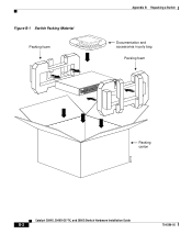
Figure B-1 Switch Packing Material Packing foam SCTaAtaTlyUsSt 2948G Appendix B Repacking a Switch Documentation and accessories in poly bag Packing foam CONSOLE 1000Base - X 10BaseT Packing carton 29715 Catalyst 2984G, 2948G-GE-TX, and 2980G Switch Hardware Installation Guide B-2 78-6286-05
Figure B-1 Switch Packing Material Packing foam SCTaAtaTlyUsSt 2948G Appendix B Repacking a Switch Documentation and accessories in poly bag Packing foam CONSOLE 1000Base - X 10BaseT Packing carton 29715 Catalyst 2984G, 2948G-GE-TX, and 2980G Switch Hardware Installation Guide B-2 78-6286-05
Hardware Installation Guide
Page 136
... switches) 3-4 shipping container contents (Catalyst 2948G-GE-TX) 3-5 checklist rack-mount 3-7 site planning 2-7 Cisco Discovery Protocol See CDP Cisco Group Management Protocol See CGMP CLI 1-5 command-line interface See CLI commands show port 4-9 configuration, patch cord (figure) 4-11 connecting to 10/100/1000 ports 3-20 to 3-22 to 10/100 ports 3-20 to 3-22 to console...
... switches) 3-4 shipping container contents (Catalyst 2948G-GE-TX) 3-5 checklist rack-mount 3-7 site planning 2-7 Cisco Discovery Protocol See CDP Cisco Group Management Protocol See CGMP CLI 1-5 command-line interface See CLI commands show port 4-9 configuration, patch cord (figure) 4-11 connecting to 10/100/1000 ports 3-20 to 3-22 to 10/100 ports 3-20 to 3-22 to console...