Hardware Installation Guide
Page 6
.../100 and 10/100/1000 Ports 1-6 Catalyst 2948G and 2980G Switch Ports 1-7 Catalyst 2948G-GE-TX Switch Ports 1-7 Switch Components 1-7 Management Ports 1-8 Console Serial Port 1-8 10BASE-T and 10/100BASE-T Ports 1-8 Front Panel LEDs 1-8 Airflow 1-9 Power Supplies 1-11 2 C H A P T E R Site Planning 2-1 Site Power Requirements and Heat Dissipation 2-2 System Ground Connection Guidelines (Catalyst 2948G and 2980G Switches Only) 2-3 Connecting the Switch to Earth Ground 2-5 Site-Planning Checklist...
.../100 and 10/100/1000 Ports 1-6 Catalyst 2948G and 2980G Switch Ports 1-7 Catalyst 2948G-GE-TX Switch Ports 1-7 Switch Components 1-7 Management Ports 1-8 Console Serial Port 1-8 10BASE-T and 10/100BASE-T Ports 1-8 Front Panel LEDs 1-8 Airflow 1-9 Power Supplies 1-11 2 C H A P T E R Site Planning 2-1 Site Power Requirements and Heat Dissipation 2-2 System Ground Connection Guidelines (Catalyst 2948G and 2980G Switches Only) 2-3 Connecting the Switch to Earth Ground 2-5 Site-Planning Checklist...
Hardware Installation Guide
Page 8
...Problem Solving to the System Component Level 5-2 Identifying Startup Problems 5-3 Troubleshooting the Power Supply 5-4 Contacting Customer Service 5-5 A A P P E N D I X Specifications A-1 Console Serial Port A-1 10BASE-T and 10/100BASE-T Ethernet Management Ports A-2 Catalyst 2948G Switch Specifications A-2 Catalyst 2948G-GE-TX Switch Specifications A-5 Catalyst 2980G Switch Specifications A-6 B A P P E N D I X Repacking a Switch B-1 C A P P E N D I X Differential Mode Delay C-1 D A P P E N D I X Translated Safety Warnings D-1 Warning Definition D-2 Safety Information Referral Warning...
...Problem Solving to the System Component Level 5-2 Identifying Startup Problems 5-3 Troubleshooting the Power Supply 5-4 Contacting Customer Service 5-5 A A P P E N D I X Specifications A-1 Console Serial Port A-1 10BASE-T and 10/100BASE-T Ethernet Management Ports A-2 Catalyst 2948G Switch Specifications A-2 Catalyst 2948G-GE-TX Switch Specifications A-5 Catalyst 2980G Switch Specifications A-6 B A P P E N D I X Repacking a Switch B-1 C A P P E N D I X Differential Mode Delay C-1 D A P P E N D I X Translated Safety Warnings D-1 Warning Definition D-2 Safety Information Referral Warning...
Hardware Installation Guide
Page 9
INDEX Laser Radiation D-11 Attaching the Cisco RPS (model PWR300-AC-RPS-N1) D-13 Attaching the Cisco RPS (model PWR600-AC-RPS) D-14 Attaching the Cisco RPS (model PWR675-AC-RPS-N1) D-15 Redundant Power Supply Connection Warning D-17 Switch Installation Warning D-18 Chassis Warning for Rack-Mounting and Servicing D-20 Contents 78-6286-05 Catalyst 2984G, 2948G-GE-TX, and 2980G Switch Hardware Installation Guide ix
INDEX Laser Radiation D-11 Attaching the Cisco RPS (model PWR300-AC-RPS-N1) D-13 Attaching the Cisco RPS (model PWR600-AC-RPS) D-14 Attaching the Cisco RPS (model PWR675-AC-RPS-N1) D-15 Redundant Power Supply Connection Warning D-17 Switch Installation Warning D-18 Chassis Warning for Rack-Mounting and Servicing D-20 Contents 78-6286-05 Catalyst 2984G, 2948G-GE-TX, and 2980G Switch Hardware Installation Guide ix
Hardware Installation Guide
Page 12
... also contact the Cisco service and support website for as long as its service center will use commercially reasonable efforts to refund the purchase price as the original end user continues to own or use the product, provided that the fan and power supply warranty is limited ...RMA) request. Select the language in which you purchased the product. The Cisco warranty page appears. If you purchased the product directly from Adobe's website: http://www.adobe.com 3. Catalyst 2984G, 2948G-GE-TX, and 2980G Switch Hardware Installation Guide xii 78-6286-05 You can download the reader from...
... also contact the Cisco service and support website for as long as its service center will use commercially reasonable efforts to refund the purchase price as the original end user continues to own or use the product, provided that the fan and power supply warranty is limited ...RMA) request. Select the language in which you purchased the product. The Cisco warranty page appears. If you purchased the product directly from Adobe's website: http://www.adobe.com 3. Catalyst 2984G, 2948G-GE-TX, and 2980G Switch Hardware Installation Guide xii 78-6286-05 You can download the reader from...
Hardware Installation Guide
Page 34
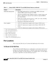
..." port.) • Performance management information Power supplies • 120 W AC internal power supply on the Catalyst 2948G switch • 156 W AC internal power supply on the Catalyst 2948G-GE-TX switch • 175 W AC internal power supply on the switches. 10/100 and 10/100/1000 Ports The 10/100 and 10/100/1000 ports are configured in vertical pairs. CDP = Cisco Discovery Protocol 6. PAgP = Port...
..." port.) • Performance management information Power supplies • 120 W AC internal power supply on the Catalyst 2948G switch • 156 W AC internal power supply on the Catalyst 2948G-GE-TX switch • 175 W AC internal power supply on the switches. 10/100 and 10/100/1000 Ports The 10/100 and 10/100/1000 ports are configured in vertical pairs. CDP = Cisco Discovery Protocol 6. PAgP = Port...
Hardware Installation Guide
Page 36
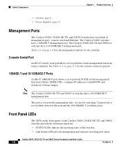
... switches. The Catalyst 2948G switches have a 10/100BASE-T management port. Front Panel LEDs The LEDs on page 1-9 lists the management options for switching. Switch Components Chapter 1 Product Overview • Airflow, page 9 • Power Supplies, page 11 Management Ports The Catalyst 2948G, 2948G-GE-TX, and 2980G switches have a 10/100BASE-T management port. The Catalyst 2948G-GE-TX and 2980G-A switches have two kinds of the switches...
... switches. The Catalyst 2948G switches have a 10/100BASE-T management port. Front Panel LEDs The LEDs on page 1-9 lists the management options for switching. Switch Components Chapter 1 Product Overview • Airflow, page 9 • Power Supplies, page 11 Management Ports The Catalyst 2948G, 2948G-GE-TX, and 2980G switches have a 10/100BASE-T management port. The Catalyst 2948G-GE-TX and 2980G-A switches have two kinds of the switches...

Hardware Installation Guide
Page 37
A test other end. 78-6286-05 Catalyst 2984G, 2948G-GE-TX, and 2980G Switch Hardware Installation Guide 1-9 System boot or diagnostic tests in Standby mode. Power supply is disabled by user. The fans exhaust warm air from one end and...." Chapter 1 Product Overview Switch Components • PSI LED indicates the internal power supply status on the Catalyst 2948G switch. • PWR LED indicates the internal power supply status on self-test indicates faulty port. Switch is operational. Port is disabled. On the Catalyst 2948G and 2980G switches, the system fan assembly ...
A test other end. 78-6286-05 Catalyst 2984G, 2948G-GE-TX, and 2980G Switch Hardware Installation Guide 1-9 System boot or diagnostic tests in Standby mode. Power supply is disabled by user. The fans exhaust warm air from one end and...." Chapter 1 Product Overview Switch Components • PSI LED indicates the internal power supply status on the Catalyst 2948G switch. • PWR LED indicates the internal power supply status on self-test indicates faulty port. Switch is operational. Port is disabled. On the Catalyst 2948G and 2980G switches, the system fan assembly ...
Hardware Installation Guide
Page 39
... used with an optional Cisco Redundant Power System (RPS). 78-6286-05 Catalyst 2984G, 2948G-GE-TX, and 2980G Switch Hardware Installation Guide 1-11 If the power supply becomes excessively hot, it shuts down to maintain normal system operation by correcting adverse environmental conditions before loss of the power supply and report the status using switch software. Chapter 1 Product Overview...
... used with an optional Cisco Redundant Power System (RPS). 78-6286-05 Catalyst 2984G, 2948G-GE-TX, and 2980G Switch Hardware Installation Guide 1-11 If the power supply becomes excessively hot, it shuts down to maintain normal system operation by correcting adverse environmental conditions before loss of the power supply and report the status using switch software. Chapter 1 Product Overview...
Hardware Installation Guide
Page 40
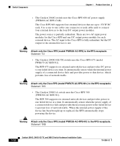
... RPS automatically stops powering the device. Statement 100B 1-12 Catalyst 2984G, 2948G-GE-TX, and 2980G Switch Hardware Installation Guide 78-6286-05 It automatically senses when the internal power supply of a connected device fails and provides power to one connector at a time. Switch Components Chapter 1 Product Overview • The Catalyst 2948G switch uses the Cisco RPS 600 AC power supply (PWR600-AC-RPS...
... RPS automatically stops powering the device. Statement 100B 1-12 Catalyst 2984G, 2948G-GE-TX, and 2980G Switch Hardware Installation Guide 78-6286-05 It automatically senses when the internal power supply of a connected device fails and provides power to one connector at a time. Switch Components Chapter 1 Product Overview • The Catalyst 2948G switch uses the Cisco RPS 600 AC power supply (PWR600-AC-RPS...
Hardware Installation Guide
Page 41
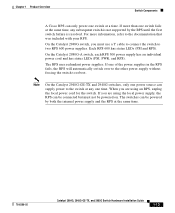
... will automatically switch over to the other power supply without forcing the switch to the documentation that was included with your RPS. If one switch fails at the same time. 78-6286-05 Catalyst 2984G, 2948G-GE-TX, and 2980G Switch Hardware Installation Guide 1-13 Chapter 1 Product Overview Switch Components A Cisco RPS can only power one switch at any subsequent switch is not...
... will automatically switch over to the other power supply without forcing the switch to the documentation that was included with your RPS. If one switch fails at the same time. 78-6286-05 Catalyst 2984G, 2948G-GE-TX, and 2980G Switch Hardware Installation Guide 1-13 Chapter 1 Product Overview Switch Components A Cisco RPS can only power one switch at any subsequent switch is not...
Hardware Installation Guide
Page 44
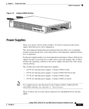
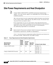
... Catalyst 2948G, 2948G-GE-TX, and 2980G switches have internal power supplies. All of the switches support Cisco Redundant Power System (RPS) for the Catalyst 2948G, 2948G-GE-TX, and 2980G switches. This section provides site power requirements and heat dissipation specifications for redundant operation. Heat specifications are used for determining the air-conditioning requirements for the Catalyst 2948G, 2948G-GE-TX, and 2980G switches. Table 2-1 describes the power...
... Catalyst 2948G, 2948G-GE-TX, and 2980G switches have internal power supplies. All of the switches support Cisco Redundant Power System (RPS) for the Catalyst 2948G, 2948G-GE-TX, and 2980G switches. This section provides site power requirements and heat dissipation specifications for redundant operation. Heat specifications are used for determining the air-conditioning requirements for the Catalyst 2948G, 2948G-GE-TX, and 2980G switches. Table 2-1 describes the power...

Hardware Installation Guide
Page 45
... grounding holes on the Catalyst 2948G switches and Figure 2-2 for the location on the Catalyst 2980G switches. 78-6286-05 Catalyst 2984G, 2948G-GE-TX, and 2980G Switch Hardware Installation Guide 2-3 Chapter 2 Site Planning System Ground Connection Guidelines (Catalyst 2948G and 2980G Switches Only) Table 2-1 Power Requirements and Heat Dissipation Specifications (continued) Model Number/ Module Type Catalyst 2980G switch Catalyst 2980G-A switch Power Supply Output (Watts) 175 156...
... grounding holes on the Catalyst 2948G switches and Figure 2-2 for the location on the Catalyst 2980G switches. 78-6286-05 Catalyst 2984G, 2948G-GE-TX, and 2980G Switch Hardware Installation Guide 2-3 Chapter 2 Site Planning System Ground Connection Guidelines (Catalyst 2948G and 2980G Switches Only) Table 2-1 Power Requirements and Heat Dissipation Specifications (continued) Model Number/ Module Type Catalyst 2980G switch Catalyst 2980G-A switch Power Supply Output (Watts) 175 156...

Hardware Installation Guide
Page 49
... Prepare the other end of receptacle to ensure adequate earth ground for power failures 4 Grounding evaluation: Circuit breaker size 78-6286-05 Catalyst 2984G, 2948G-GE-TX, and 2980G Switch Hardware Installation Guide 2-7 Planning Activity Verified By Time Date 1 Space ...redundant power supplies UPS for the switch. Table 2-2 Site-Planning Checklist Task No. Completing each activity helps ensure a successful switch installation. Site-Planning Checklist Table 2-2 lists the site-planning activities that you should complete before you install the Catalyst 2948G, 2948G-GE-...
... Prepare the other end of receptacle to ensure adequate earth ground for power failures 4 Grounding evaluation: Circuit breaker size 78-6286-05 Catalyst 2984G, 2948G-GE-TX, and 2980G Switch Hardware Installation Guide 2-7 Planning Activity Verified By Time Date 1 Space ...redundant power supplies UPS for the switch. Table 2-2 Site-Planning Checklist Task No. Completing each activity helps ensure a successful switch installation. Site-Planning Checklist Table 2-2 lists the site-planning activities that you should complete before you install the Catalyst 2948G, 2948G-GE-...
Hardware Installation Guide
Page 69
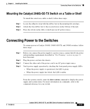
... to the command reference for your switch. 78-6286-05 Catalyst 2984G, 2948G-GE-TX, and 2980G Switch Hardware Installation Guide 3-19 Connecting Power to the Switches To connect power to Catalyst 2948G, 2948G-GE-TX, and 2980G switches, follow these steps: Step 1 Step 2 Step 3 Step 4 Before you connect the power supply to a power source, ensure that all site power and grounding requirements described in...
... to the command reference for your switch. 78-6286-05 Catalyst 2984G, 2948G-GE-TX, and 2980G Switch Hardware Installation Guide 3-19 Connecting Power to the Switches To connect power to Catalyst 2948G, 2948G-GE-TX, and 2980G switches, follow these steps: Step 1 Step 2 Step 3 Step 4 Before you connect the power supply to a power source, ensure that all site power and grounding requirements described in...
Hardware Installation Guide
Page 73
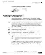
... When two power supplies are operational. Note Many of the switch. Chapter 3 Installing the Switch Verifying Switch Operation Figure 3-16 Ethernet Cable with RJ-45 Connector 98459 Verifying Switch Operation After you... configure the interfaces. While the system initializes, check that the STATUS LED on the supervisor engine is complete, the console screen displays a script and system banner. 78-6286-05 Catalyst 2984G, 2948G...
... When two power supplies are operational. Note Many of the switch. Chapter 3 Installing the Switch Verifying Switch Operation Figure 3-16 Ethernet Cable with RJ-45 Connector 98459 Verifying Switch Operation After you... configure the interfaces. While the system initializes, check that the STATUS LED on the supervisor engine is complete, the console screen displays a script and system banner. 78-6286-05 Catalyst 2984G, 2948G...
Hardware Installation Guide
Page 91
...are rarely the source of problems at startup; For configuration questions or problems, refer to troubleshoot the Catalyst 2948G, 2948G-GE-TX, and 2980G switch installations. Temperature conditions above the maximum acceptable level are included in this chapter to help isolate the ...Component Level, page 5-2 • Identifying Startup Problems, page 5-3 • Troubleshooting the Power Supply, page 5-4 • Contacting Customer Service, page 5-5 If you have problems starting up your switch. 78-6286-05 Catalyst 2984G, 2948G-GE-TX, and 2980G Switch Hardware Installation Guide 5-1
...are rarely the source of problems at startup; For configuration questions or problems, refer to troubleshoot the Catalyst 2948G, 2948G-GE-TX, and 2980G switch installations. Temperature conditions above the maximum acceptable level are included in this chapter to help isolate the ...Component Level, page 5-2 • Identifying Startup Problems, page 5-3 • Troubleshooting the Power Supply, page 5-4 • Contacting Customer Service, page 5-5 If you have problems starting up your switch. 78-6286-05 Catalyst 2984G, 2948G-GE-TX, and 2980G Switch Hardware Installation Guide 5-1
Hardware Installation Guide
Page 92
...; Listen to the fan assembly to determine if it will shut down because of the following subsystems: • Power supply-Includes the power supplies and power supply fans (see "Troubleshooting the Power Supply" section on . Catalyst 2984G, 2948G-GE-TX, and 2980G Switch Hardware Installation Guide 5-2 78-6286-05 The first step is to compare what the system is doing . The...
...; Listen to the fan assembly to determine if it will shut down because of the following subsystems: • Power supply-Includes the power supplies and power supply fans (see "Troubleshooting the Power Supply" section on . Catalyst 2984G, 2948G-GE-TX, and 2980G Switch Hardware Installation Guide 5-2 78-6286-05 The first step is to compare what the system is doing . The...
Hardware Installation Guide
Page 93
... Installation Guide 5-3 After you connect the power cord to the Catalyst 2948G, 2948G-GE-TX, or 2980G switches, follow these steps: Step 1 Step 2 Step 3 You should contact a customer service representative. The Link LED blinks amber continuously if the port is detected, the Link LED turns off. Check the power supply LEDs as follows: • The STATUS LED...
... Installation Guide 5-3 After you connect the power cord to the Catalyst 2948G, 2948G-GE-TX, or 2980G switches, follow these steps: Step 1 Step 2 Step 3 You should contact a customer service representative. The Link LED blinks amber continuously if the port is detected, the Link LED turns off. Check the power supply LEDs as follows: • The STATUS LED...
Hardware Installation Guide
Page 94
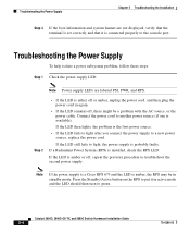
...properly to the console port. Note If the power supply is a Cisco RPS 675 and the LED is either off or amber, unplug the power cord, and then plug the power cord in active mode and the LED should then turn to a new power source, replace the power cord. Step 2 • If the ... a problem with the AC source, or the power cable. Connect the power cord to another power source (if one is the first power source. • If the LED fails to light after you connect the power supply to green. Catalyst 2984G, 2948G-GE-TX, and 2980G Switch Hardware Installation Guide 5-4 78-6286-05 If the...
...properly to the console port. Note If the power supply is a Cisco RPS 675 and the LED is either off or amber, unplug the power cord, and then plug the power cord in active mode and the LED should then turn to a new power source, replace the power cord. Step 2 • If the ... a problem with the AC source, or the power cable. Connect the power cord to another power source (if one is the first power source. • If the LED fails to light after you connect the power supply to green. Catalyst 2984G, 2948G-GE-TX, and 2980G Switch Hardware Installation Guide 5-4 78-6286-05 If the...

Hardware Installation Guide
Page 95
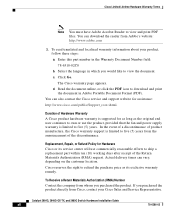
...the troubleshooting suggestions in this chapter, contact a customer service representative for installation and configuration details. Disconnect power from the internal power supply before turning the power on the right of the rear panel of the chassis) • Type of software and release number...the switch • Chassis serial number (located on a label on for redundant power protection. Chapter 5 Troubleshooting the Installation Contacting Customer Service Note If you have already taken to isolate and resolve the problem 78-6286-05 Catalyst 2984G, 2948G-GE-TX, and 2980G Switch ...
...the troubleshooting suggestions in this chapter, contact a customer service representative for installation and configuration details. Disconnect power from the internal power supply before turning the power on the right of the rear panel of the chassis) • Type of software and release number...the switch • Chassis serial number (located on a label on for redundant power protection. Chapter 5 Troubleshooting the Installation Contacting Customer Service Note If you have already taken to isolate and resolve the problem 78-6286-05 Catalyst 2984G, 2948G-GE-TX, and 2980G Switch ...

