

User Guide
Page 3
The 2621XM/2651XM Cryptographic Module Figure 1 The 2621XM/2651XM Router POWER RPS ACTIVITY Cisco 2600SERIES 99493 The 2621XM and 2651XM Routers are located on the motherboard. The cryptographic boundary includes the connection apparatus between the WIC...power needed for the dynamic requirements of Remote Access WANs via IPSec, Layer 2 Forwarding (L2F) and Layer 2 Tunneling Protocols (L2TP) make the Cisco 2600 an ideal platform for the router are multiple-chip standalone cryptographic modules. Module Interfaces The interfaces for building virtual private networks or outsourced dial...
The 2621XM/2651XM Cryptographic Module Figure 1 The 2621XM/2651XM Router POWER RPS ACTIVITY Cisco 2600SERIES 99493 The 2621XM and 2651XM Routers are located on the motherboard. The cryptographic boundary includes the connection apparatus between the WIC...power needed for the dynamic requirements of Remote Access WANs via IPSec, Layer 2 Forwarding (L2F) and Layer 2 Tunneling Protocols (L2TP) make the Cisco 2600 an ideal platform for the router are multiple-chip standalone cryptographic modules. Module Interfaces The interfaces for building virtual private networks or outsourced dial...
User Guide
Page 5
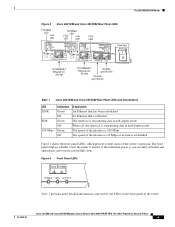
...Router Figure 3 Cisco 2621XM and Cisco 2651XM Rear Panel... Mbps Link SERIAL 1 CONN SERIAL 0 SEE MANUAL BEFORE INSTALLATION WIC CONN 2A/S FDX W0 Cisco 2621 10/100 ETHERNET 0/1 10/100 ETHERNET 0/0 CONSOLE AUX 10/100BASE-T Ethernet 0/1 (RJ...RJ-45) Auxiliary port (RJ-45) Console port (RJ-45) 99495 Table 1 Cisco 2621XM and Cisco 2651XM Rear Panel LEDs and Descriptions LED LINK FDX 100 Mbps Indication Green Off Green...shows the front panel LEDs, which provide overall status of the router: Cisco 2621XM and Cisco 2651XM Modular Access Routers with AIM-VPN/EP FIPS 140-2 Non-Proprietary ...
...Router Figure 3 Cisco 2621XM and Cisco 2651XM Rear Panel... Mbps Link SERIAL 1 CONN SERIAL 0 SEE MANUAL BEFORE INSTALLATION WIC CONN 2A/S FDX W0 Cisco 2621 10/100 ETHERNET 0/1 10/100 ETHERNET 0/0 CONSOLE AUX 10/100BASE-T Ethernet 0/1 (RJ...RJ-45) Auxiliary port (RJ-45) Console port (RJ-45) 99495 Table 1 Cisco 2621XM and Cisco 2651XM Rear Panel LEDs and Descriptions LED LINK FDX 100 Mbps Indication Green Off Green...shows the front panel LEDs, which provide overall status of the router: Cisco 2621XM and Cisco 2651XM Modular Access Routers with AIM-VPN/EP FIPS 140-2 Non-Proprietary ...

User Guide
Page 6
...Router Table 2 Cisco 2621XM and Cisco 2651XM Front Panel LEDs and Descriptions LED Indication Description Power Green Power is supplied to the router and the router is operational RPS1 Off Green The router is not powered on RPS is attached and operational Off No RPS is attached Blink RPS is attached, ...but has a failure Activity Off In the Cisco IOS software, but no network activity Blink (500 ms ON, 500 ms OFF) In...
...Router Table 2 Cisco 2621XM and Cisco 2651XM Front Panel LEDs and Descriptions LED Indication Description Power Green Power is supplied to the router and the router is operational RPS1 Off Green The router is not powered on RPS is attached and operational Off No RPS is attached Blink RPS is attached, ...but has a failure Activity Off In the Cisco IOS software, but no network activity Blink (500 ms ON, 500 ms OFF) In...
User Guide
Page 9
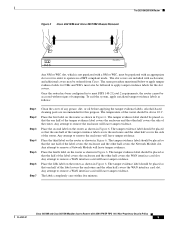
...shown in Figure 6. Any attempt to remove a WAN interface card will leave tamper evidence. The tamper evidence label should be ordered from Cisco. Any attempt to remove a WAN interface card will leave tamper evidence. The labels completely cure within five minutes. Place the second label...-based cleaning pads are included with each router, and additional covers may be above 10 C. Figure 5 Cisco 2621XM and Cisco 2651XM Chassis Removal The 2621XM/2651XM Router POWER RPS ACTIVITY Cisco 2600 SERIES 99497 Any NM or WIC slot, which is not populated with a NM or WIC, must...
...shown in Figure 6. Any attempt to remove a WAN interface card will leave tamper evidence. The tamper evidence label should be ordered from Cisco. Any attempt to remove a WAN interface card will leave tamper evidence. The labels completely cure within five minutes. Place the second label...-based cleaning pads are included with each router, and additional covers may be above 10 C. Figure 5 Cisco 2621XM and Cisco 2651XM Chassis Removal The 2621XM/2651XM Router POWER RPS ACTIVITY Cisco 2600 SERIES 99497 Any NM or WIC slot, which is not populated with a NM or WIC, must...
User Guide
Page 10
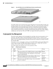
...Diffie-Hellman (DH) exchange. Zeroized after the generation of 400 bites; Zeroized when IKE session is zeroized periodically. DRAM (plaintext) Cisco 2621XM and Cisco 2651XM Modular Access Routers with self-adhesive backing. The module supports the following : curled corners, bubbling, crinkling, rips, tears, ...SERIAL 1 CONN SERIAL 0 WIC CONN 2T SEE MANUAL BEFORE INSTALLATION W0 Cisco 2611 LINK ETHERNET 1 ACT LINK ETHERNET 0 ACT CONSOLE AUX 100-240V- 1A 50/60 Hz 47 W POWER RPS ACTIVITY Cisco 2600SERIES 99498 The tamper evidence seals are produced from a special thin gauge...
...Diffie-Hellman (DH) exchange. Zeroized after the generation of 400 bites; Zeroized when IKE session is zeroized periodically. DRAM (plaintext) Cisco 2621XM and Cisco 2651XM Modular Access Routers with self-adhesive backing. The module supports the following : curled corners, bubbling, crinkling, rips, tears, ...SERIAL 1 CONN SERIAL 0 WIC CONN 2T SEE MANUAL BEFORE INSTALLATION W0 Cisco 2611 LINK ETHERNET 1 ACT LINK ETHERNET 0 ACT CONSOLE AUX 100-240V- 1A 50/60 Hz 47 W POWER RPS ACTIVITY Cisco 2600SERIES 99498 The tamper evidence seals are produced from a special thin gauge...

Software Configuration Guide
Page 14
...; Regulatory Compliance and Safety Information • Cisco 3600 Series Routers Hardware Installation Guide • Cisco 3620 and Cisco 3640 Modular Access Routers Quick Start Guide • Cisco 3660 Modular Access Router Quick Start Guide • Cisco Network Modules Hardware Installation Guide • Cisco WAN Interface Cards Hardware Installation Guide • Cisco RPS Hardware Installation Guide • Regulatory Compliance...
...; Regulatory Compliance and Safety Information • Cisco 3600 Series Routers Hardware Installation Guide • Cisco 3620 and Cisco 3640 Modular Access Routers Quick Start Guide • Cisco 3660 Modular Access Router Quick Start Guide • Cisco Network Modules Hardware Installation Guide • Cisco WAN Interface Cards Hardware Installation Guide • Cisco RPS Hardware Installation Guide • Regulatory Compliance...

Hardware Installation Guide
Page 15
... Redundant Power Supply Interface Module in the Cisco 2691 Router Cisco RPS Hardware Installation Guide BootROM Installation for Cisco 2620 and Cisco 2621 Routers Alarm Interface Controller Patch Panel Installation Guide Software Configuration Guide for Cisco 2600 Series, Cisco 3600 Series, and Cisco 3700 Series Routers Cisco 2600 Series, Cisco 3600 Series, and Cisco 3700 Series Regulatory Compliance and Safety Information Network...
... Redundant Power Supply Interface Module in the Cisco 2691 Router Cisco RPS Hardware Installation Guide BootROM Installation for Cisco 2620 and Cisco 2621 Routers Alarm Interface Controller Patch Panel Installation Guide Software Configuration Guide for Cisco 2600 Series, Cisco 3600 Series, and Cisco 3700 Series Routers Cisco 2600 Series, Cisco 3600 Series, and Cisco 3700 Series Regulatory Compliance and Safety Information Network...

Hardware Installation Guide
Page 23
...-Panel LEDs POWER RPS ACTIVITY H11660 Table 1-2 Cisco 2600 Series Routers with 1-RU Chassis Height-Front-Panel LED Descriptions LED POWER Description Indicates the router's operating status. Chapter 1 Overview of Cisco 2600 Series Routers Reading the Front-Panel LEDs Figure 1-2 Cisco 2600 Series Router Rear... Auxiliary port Reading the Front-Panel LEDs The LEDs indicate the current operating condition of Cisco 2600 series routers. Table 1-3 and Table 1-3 describe these LEDs. OL-2171-06 Cisco 2600 Series Routers Hardware Installation Guide 1-3 Comes on the front panel of the router....
...-Panel LEDs POWER RPS ACTIVITY H11660 Table 1-2 Cisco 2600 Series Routers with 1-RU Chassis Height-Front-Panel LED Descriptions LED POWER Description Indicates the router's operating status. Chapter 1 Overview of Cisco 2600 Series Routers Reading the Front-Panel LEDs Figure 1-2 Cisco 2600 Series Router Rear... Auxiliary port Reading the Front-Panel LEDs The LEDs indicate the current operating condition of Cisco 2600 series routers. Table 1-3 and Table 1-3 describe these LEDs. OL-2171-06 Cisco 2600 Series Routers Hardware Installation Guide 1-3 Comes on the front panel of the router....

Hardware Installation Guide
Page 24
... seconds between codes)-In ROMMON, error detected. RPS = Redundant Power System Figure 1-4 Cisco 2691-Front-Panel LEDs PWR SYS ACT RPS 72100 Table 1-3 Cisco 2691-Front-Panel LED Descriptions LED Description PWR On-Power is attached and operational. On-RPS is applied to the router. Blink (less...On-System okay ACTIVITY Off-No system activity Blinking-System activity Cisco 2600 Series Routers Hardware Installation Guide 1-4 OL-2171-06 SYS/RPS Rapid blinking-System is attached, but no errors. ACTIVITY Off-In the Cisco IOS software, but has a failure. Reading the Front-...
... seconds between codes)-In ROMMON, error detected. RPS = Redundant Power System Figure 1-4 Cisco 2691-Front-Panel LEDs PWR SYS ACT RPS 72100 Table 1-3 Cisco 2691-Front-Panel LED Descriptions LED Description PWR On-Power is attached and operational. On-RPS is applied to the router. Blink (less...On-System okay ACTIVITY Off-No system activity Blinking-System activity Cisco 2600 Series Routers Hardware Installation Guide 1-4 OL-2171-06 SYS/RPS Rapid blinking-System is attached, but no errors. ACTIVITY Off-In the Cisco IOS software, but has a failure. Reading the Front-...

Hardware Installation Guide
Page 49
... on page 3-3. Chapter 3 Installing the Router Setting Up the Chassis For internal power supplies: • Cisco 2600 Series Power Supply Configuration Note • Installing AC Power Supplies in Cisco 2691 Routers For external power supplies: • Cisco RPS Hardware Installation Guide Note If there are as follows: Step 1 Step 2 Place the router upside-down...
... on page 3-3. Chapter 3 Installing the Router Setting Up the Chassis For internal power supplies: • Cisco 2600 Series Power Supply Configuration Note • Installing AC Power Supplies in Cisco 2691 Routers For external power supplies: • Cisco RPS Hardware Installation Guide Note If there are as follows: Step 1 Step 2 Place the router upside-down...
Hardware Installation Guide
Page 64
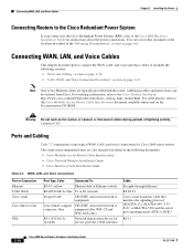
...to connect the WAN, LAN, and voice interface cables. Connecting WAN, LAN, and Voice Cables This chapter describes how to the Cisco Modular Access Router Cable Specifications document available online and on page 3-19 Note One or two Ethernet cables are also described in detail... with the router. Connecting WAN, LAN, and Voice Cables Chapter 3 Installing the Router Connecting Routers to the Cisco Redundant Power System If your router uses the Cisco Redundant Power System (RPS), refer to the Cisco RPS Hardware Installation Guide for Cisco 2600 series routers. You can be ordered from...
...to connect the WAN, LAN, and voice interface cables. Connecting WAN, LAN, and Voice Cables This chapter describes how to the Cisco Modular Access Router Cable Specifications document available online and on page 3-19 Note One or two Ethernet cables are also described in detail... with the router. Connecting WAN, LAN, and Voice Cables Chapter 3 Installing the Router Connecting Routers to the Cisco Redundant Power System If your router uses the Cisco Redundant Power System (RPS), refer to the Cisco RPS Hardware Installation Guide for Cisco 2600 series routers. You can be ordered from...

Hardware Installation Guide
Page 69
... is on -System is booted, RPS is configured for 9600 baud, 8 data bits, 1 stop bit, and no RPS failure • ACTIVITY (green)- - Continuous on . • RPS (green)- - Off-No redundant power supply (RPS) is present, RPS failure - Blinking -System is booted, RPS is present - Front Panel Indicators ...Warning The plug-socket combination must be accessible at all times because it serves as interrupts and packet transfers OL-2171-06 Cisco 2600 Series Routers Hardware Installation Guide 3-23 Statement 1019 Caution To ensure adequate cooling, never operate the router unless the ...
... is on -System is booted, RPS is configured for 9600 baud, 8 data bits, 1 stop bit, and no RPS failure • ACTIVITY (green)- - Continuous on . • RPS (green)- - Off-No redundant power supply (RPS) is present, RPS failure - Blinking -System is booted, RPS is present - Front Panel Indicators ...Warning The plug-socket combination must be accessible at all times because it serves as interrupts and packet transfers OL-2171-06 Cisco 2600 Series Routers Hardware Installation Guide 3-23 Statement 1019 Caution To ensure adequate cooling, never operate the router unless the ...

Hardware Installation Guide
Page 70
... Module (Active, Ready) LEDs might also come on the keyboard until the messages stop , which might cause the router to the Cisco router before it goes through a terminal session, you power up and connected as the first command typed when the messages stop . ...Appendix A, "Troubleshooting." Depending on . • SYS/RPS (green)- - Powering Up the Router Chapter 3 Installing the Router Routers with a configuration file and is ready for initial configuration using Cisco Router and Security Device Manager (SDM). 3-24 Cisco 2600 Series Routers Hardware Installation Guide OL-2171-06 ...
... Module (Active, Ready) LEDs might also come on the keyboard until the messages stop , which might cause the router to the Cisco router before it goes through a terminal session, you power up and connected as the first command typed when the messages stop . ...Appendix A, "Troubleshooting." Depending on . • SYS/RPS (green)- - Powering Up the Router Chapter 3 Installing the Router Routers with a configuration file and is ready for initial configuration using Cisco Router and Security Device Manager (SDM). 3-24 Cisco 2600 Series Routers Hardware Installation Guide OL-2171-06 ...

Hardware Installation Guide
Page 80
... notices, security advisories, and troubleshooting information maintained by the Cisco redundant power system are described in the publication Cisco RPS Installation Guide. If you to the Cisco IOS System Error Messages online document at the following URL: http://www.cisco.com/warp/public/474/pswdrec_2600.shtml Cisco Technical Assistance Center The following prompts: Router> (indicates user...
... notices, security advisories, and troubleshooting information maintained by the Cisco redundant power system are described in the publication Cisco RPS Installation Guide. If you to the Cisco IOS System Error Messages online document at the following URL: http://www.cisco.com/warp/public/474/pswdrec_2600.shtml Cisco Technical Assistance Center The following prompts: Router> (indicates user...

Hardware Installation Guide
Page 101
... types 2-9 LEDs 100 Mbps, in 1-RU chassis 1-7 100 Mbps, in Cisco 2691 1-8 ACT, in 1-RU chassis 1-7 ACT, in Cisco 2691 1-8 ACTIVITY, in 1-RU chassis 1-4 ACTIVITY, in Cisco 2691 1-4 CF1, in Cisco 2691 1-8 FDX, in 1-RU chassis 1-7 front panel 1-3 to 1-4 interpretation... of A-2 LINK, in 1-RU chassis 1-7 LINK, in Cisco 2691 1-8 Power, in 1-RU chassis 1-3 Power, in Cisco 2691 1-4 rear panel 1-5 to 1-8 RPS, in 1-RU chassis 1-4 SYS/RPS, in Cisco 2691 1-4 lightning safety 2-2 LINK LED 1-7 M meminfo command B-5, B-6 memory 1-2 to 1-9 modem connection...
... types 2-9 LEDs 100 Mbps, in 1-RU chassis 1-7 100 Mbps, in Cisco 2691 1-8 ACT, in 1-RU chassis 1-7 ACT, in Cisco 2691 1-8 ACTIVITY, in 1-RU chassis 1-4 ACTIVITY, in Cisco 2691 1-4 CF1, in Cisco 2691 1-8 FDX, in 1-RU chassis 1-7 front panel 1-3 to 1-4 interpretation... of A-2 LINK, in 1-RU chassis 1-7 LINK, in Cisco 2691 1-8 Power, in 1-RU chassis 1-3 Power, in Cisco 2691 1-4 rear panel 1-5 to 1-8 RPS, in 1-RU chassis 1-4 SYS/RPS, in Cisco 2691 1-4 lightning safety 2-2 LINK LED 1-7 M meminfo command B-5, B-6 memory 1-2 to 1-9 modem connection...
