
Service Manual
Page 3
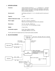
...including roll-holder Weight: 1.5 kg (3.3 lbs) Consumable supplies: Printer ribbon (RB-02 or GB-02) Roll papaer (Width 58 × 60 ø mm) The AC outlet must be located near the unit and must be easily accessible. 2. Capacity: 12 digits Ambient temperature range: 0 °C ~ 40 °C (32 ...°F ~ 104 °F) Power supply: (AC 120 V, 100/120 V, 230/240 V) Rated current and voltage are printed on the calculator. 1. BLOCK DIAGRAM Display tube 13-BT-144G ...
...including roll-holder Weight: 1.5 kg (3.3 lbs) Consumable supplies: Printer ribbon (RB-02 or GB-02) Roll papaer (Width 58 × 60 ø mm) The AC outlet must be located near the unit and must be easily accessible. 2. Capacity: 12 digits Ambient temperature range: 0 °C ~ 40 °C (32 ...°F ~ 104 °F) Power supply: (AC 120 V, 100/120 V, 230/240 V) Rated current and voltage are printed on the calculator. 1. BLOCK DIAGRAM Display tube 13-BT-144G ...
Service Manual
Page 4
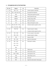
3. Signal I/O 1 ~ 7, 64 P00 ~ P13 Out 8 ~ 12 P20 ~ P22, P32, P33 In 13 IRQ In 14 DEBIN In ...keyboard Timing pulse signal from printer Reset pulse (Not used) Auxiliary timing (VDD) Motor control signal Ribbon shift signal for printer Character selective signal for printer Segment signal for display, Character selective signal for printer... Common signal for slide switch, Segment signal for display Input port (VDD) Signal from slide switch Digit signal for display GND terminal VDD terminal (+32 V) Clock signal for CPU VSS terminal (+27 V) Not used Signal...
3. Signal I/O 1 ~ 7, 64 P00 ~ P13 Out 8 ~ 12 P20 ~ P22, P32, P33 In 13 IRQ In 14 DEBIN In ...keyboard Timing pulse signal from printer Reset pulse (Not used) Auxiliary timing (VDD) Motor control signal Ribbon shift signal for printer Character selective signal for printer Segment signal for display, Character selective signal for printer... Common signal for slide switch, Segment signal for display Input port (VDD) Signal from slide switch Digit signal for display GND terminal VDD terminal (+32 V) Clock signal for CPU VSS terminal (+27 V) Not used Signal...
Service Manual
Page 11
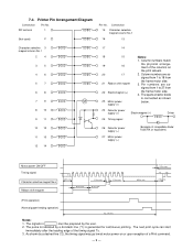
...7 6 8 7 9 8 10 9 11 10 12 11 13 12 14 17 14 18 15 Notes: 1. The pulse is indicated by a dot-dash line (*1) is connected as - Printer Pin Arrangement Diagram Connection Pin No. The spark arrestor diode is generated for continuous printing. signed from 1 to 18 from 22 Electromagnet (+) the...user. 2. Column numbers match 19 16 the physical arrangement of the columns on or upon reception of a Print command. - 9 - 7-4. signed from 1 to 27 from 21 Ribbon shift magnet the frame motor side. 3. Pin numbers are as shown M 23 Motor power supply (+) ...
...7 6 8 7 9 8 10 9 11 10 12 11 13 12 14 17 14 18 15 Notes: 1. The pulse is indicated by a dot-dash line (*1) is connected as - Printer Pin Arrangement Diagram Connection Pin No. The spark arrestor diode is generated for continuous printing. signed from 1 to 18 from 22 Electromagnet (+) the...user. 2. Column numbers match 19 16 the physical arrangement of the columns on or upon reception of a Print command. - 9 - 7-4. signed from 1 to 27 from 21 Ribbon shift magnet the frame motor side. 3. Pin numbers are as shown M 23 Motor power supply (+) ...


