
Service Manual
Page 3
Chapter 2 Basic Operation explains how copies are reproduced. It also explains the timing at which image formation-related mechanisms are operated, and shows how they may be disassembled/assembled and adjusted. ... may be disassembled/assembled and adjusted. Appendix contains a general timing chart and general circuit diagrams. COPYRIGHT © 1999 CANON INC. INTRODUCTION This service manual has been prepared for the PC800/900 Series machines, providing basic information used for servicing the machines in relation to ensure their timing of installation, and shows how the...
Chapter 2 Basic Operation explains how copies are reproduced. It also explains the timing at which image formation-related mechanisms are operated, and shows how they may be disassembled/assembled and adjusted. ... may be disassembled/assembled and adjusted. Appendix contains a general timing chart and general circuit diagrams. COPYRIGHT © 1999 CANON INC. INTRODUCTION This service manual has been prepared for the PC800/900 Series machines, providing basic information used for servicing the machines in relation to ensure their timing of installation, and shows how the...
Service Manual
Page 9
... Basic Operations 8-4 D. DISASSEMBLY/ASSEMBLY ..... 8-18 A. MOVING THE MACHINE .......... 9-12 CHAPTER 10 MAINTENANCE AND SERVICING I. STORING AND HANDLING THE CARTRIDGE 10-2 A. Unpacking and Installation ....9-2 B. CANON PC800s/900s REV.0 AUG. 1999 PRINTED IN JAPAN (IMPRIME AU... JAPON) vii FANS 7-1 II. UNPACKING AND INSTALLATION 9-2 A. Detecting an Error on the Composite Power Supply PCB 7-6 D. PERIODICALLY REPLACED PARTS 10-1 II. Outline of the Power Supply System 7-3 B. Placing Copy...
... Basic Operations 8-4 D. DISASSEMBLY/ASSEMBLY ..... 8-18 A. MOVING THE MACHINE .......... 9-12 CHAPTER 10 MAINTENANCE AND SERVICING I. STORING AND HANDLING THE CARTRIDGE 10-2 A. Unpacking and Installation ....9-2 B. CANON PC800s/900s REV.0 AUG. 1999 PRINTED IN JAPAN (IMPRIME AU... JAPON) vii FANS 7-1 II. UNPACKING AND INSTALLATION 9-2 A. Detecting an Error on the Composite Power Supply PCB 7-6 D. PERIODICALLY REPLACED PARTS 10-1 II. Outline of the Power Supply System 7-3 B. Placing Copy...
Service Manual
Page 11
USING THE MACHINE 1-15 A. ADF 1-8 III. CANON PC800s/900s REV.0 AUG. 1999 PRINTED IN JAPAN (IMPRIME AU JAPON) Copier 1-2 B. FEATURES 1-1 II. Cross Section 1-13 IV. Control Panel 1-15 V. I. External View 1-10 B. ROUTINE MAINTENANCE BY THE USER 1-17 VI. IMAGE FORMATION 1-20 A. Outline 1-20 COPYRIGHT © 1999 CANON INC. NAMES OF PARTS 1-10 A. SPECIFICATIONS 1-2 A. CHAPTER 1 GENERAL DESCRIPTION This chapter provides specifications of the machine, instructions on how to operate the machine, and an outline of copying process.
USING THE MACHINE 1-15 A. ADF 1-8 III. CANON PC800s/900s REV.0 AUG. 1999 PRINTED IN JAPAN (IMPRIME AU JAPON) Copier 1-2 B. FEATURES 1-1 II. Cross Section 1-13 IV. Control Panel 1-15 V. I. External View 1-10 B. ROUTINE MAINTENANCE BY THE USER 1-17 VI. IMAGE FORMATION 1-20 A. Outline 1-20 COPYRIGHT © 1999 CANON INC. NAMES OF PARTS 1-10 A. SPECIFICATIONS 1-2 A. CHAPTER 1 GENERAL DESCRIPTION This chapter provides specifications of the machine, instructions on how to operate the machine, and an outline of copying process.
Service Manual
Page 13
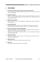
... less on . 4. The user may expect quality copy images at 20°C room temperature), enabling speedy copying work . 6. FEATURES 1. All-in 1% increments. 2. ADF Type • Continuous copying is 0 sec (at all times as long as a business card. 5. CANON PC800s/900s REV.0 AUG. 1999 PRINTED IN JAPAN...-on the average, 0.02 ppm or less at maximum (1/100 to make jam removal easy. 8. COPYRIGHT © 1999 CANON INC. Personal Copier with existing Canon machines). 3. CHAPTER 1 GENERAL DESCRIPTION I. Large Paper Source • The source of paper may be between 70% and 141%...
... less on . 4. The user may expect quality copy images at 20°C room temperature), enabling speedy copying work . 6. FEATURES 1. All-in 1% increments. 2. ADF Type • Continuous copying is 0 sec (at all times as long as a business card. 5. CANON PC800s/900s REV.0 AUG. 1999 PRINTED IN JAPAN...-on the average, 0.02 ppm or less at maximum (1/100 to make jam removal easy. 8. COPYRIGHT © 1999 CANON INC. Personal Copier with existing Canon machines). 3. CHAPTER 1 GENERAL DESCRIPTION I. Large Paper Source • The source of paper may be between 70% and 141%...
Service Manual
Page 27
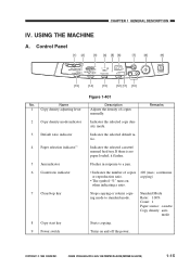
...Indicates the selected copy density mode. Turns on when indicating a ratio. 100 (max.; USING THE MACHINE A. continuous copying) Stops copying or returns copying mode to a jam. • Indicates the number of copies manually. Name 1 Copy density adjusting lever 2 Copy density mode indicator ... Paper source: cassette Copy density: auto mode Starts copying. CANON PC800s/900s REV.0 AUG. 1999 PRINTED IN JAPAN (IMPRIME AU JAPON) 1-15 Control Panel [1] [2] [3] [4] [5] [6] [7] [8] [9] [15] [14] [13] [12] [11] [10] No. COPYRIGHT © 1999 CANON INC. Flashes in ...
...Indicates the selected copy density mode. Turns on when indicating a ratio. 100 (max.; USING THE MACHINE A. continuous copying) Stops copying or returns copying mode to a jam. • Indicates the number of copies manually. Name 1 Copy density adjusting lever 2 Copy density mode indicator ... Paper source: cassette Copy density: auto mode Starts copying. CANON PC800s/900s REV.0 AUG. 1999 PRINTED IN JAPAN (IMPRIME AU JAPON) 1-15 Control Panel [1] [2] [3] [4] [5] [6] [7] [8] [9] [15] [14] [13] [12] [11] [10] No. COPYRIGHT © 1999 CANON INC. Flashes in ...
Service Manual
Page 29
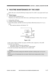
...'U6'. Caution: • You cannot start feeder cleaning mode while the machine is making copies or if an error exists. • The auto power-off mechanism does not operate while feeder cleaning mode is being executed. COPYRIGHT © 1999 CANON INC. then, dry wipe it. Feeding Belt (ADF type) b.1 Cleaning... 1) Turn on the original tray of blank copy paper (A4/LTR) on the machine, and hold down the Copy Density Mode Selection key for 4 sec or more. • The count/ratio indicator will be soiled or copy paper tends to end the mode. CANON PC800s/900s REV.0 AUG. 1999 PRINTED IN JAPAN...
...'U6'. Caution: • You cannot start feeder cleaning mode while the machine is making copies or if an error exists. • The auto power-off mechanism does not operate while feeder cleaning mode is being executed. COPYRIGHT © 1999 CANON INC. then, dry wipe it. Feeding Belt (ADF type) b.1 Cleaning... 1) Turn on the original tray of blank copy paper (A4/LTR) on the machine, and hold down the Copy Density Mode Selection key for 4 sec or more. • The count/ratio indicator will be soiled or copy paper tends to end the mode. CANON PC800s/900s REV.0 AUG. 1999 PRINTED IN JAPAN...
Service Manual
Page 33
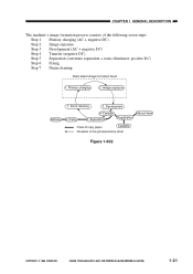
... Step 7 Drum cleaning Static latent image formation block 1. Image exposure 7. Primary charging 2. CHAPTER 1 GENERAL DESCRIPTION The machine's image formation process consists of the photosensitive drum Figure 1-602 COPYRIGHT © 1999 CANON INC. Separation Registration : Flow of copy paper Cassette : Rotation of the following seven steps: Step 1 Primary charging (AC + negative DC) Step 2 Image...
... Step 7 Drum cleaning Static latent image formation block 1. Image exposure 7. Primary charging 2. CHAPTER 1 GENERAL DESCRIPTION The machine's image formation process consists of the photosensitive drum Figure 1-602 COPYRIGHT © 1999 CANON INC. Separation Registration : Flow of copy paper Cassette : Rotation of the following seven steps: Step 1 Primary charging (AC + negative DC) Step 2 Image...
Service Manual
Page 37
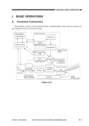
... The machine consists of four functional blocks: pickup/feeding system, exposure system, image formation system, and control system. CHAPTER 2 BASIC OPERATION I. BASIC OPERATIONS A. Control system Control panel Exposure system Copyboard Control circuit Original illuminating block Optical block Primary charging roller Image formation system Drum cleaning block Photosensitive drum Developing assembly Copy tray...
... The machine consists of four functional blocks: pickup/feeding system, exposure system, image formation system, and control system. CHAPTER 2 BASIC OPERATION I. BASIC OPERATIONS A. Control system Control panel Exposure system Copyboard Control circuit Original illuminating block Optical block Primary charging roller Image formation system Drum cleaning block Photosensitive drum Developing assembly Copy tray...
Service Manual
Page 56
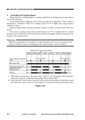
... thereby lowering the temperature of the lamp increases the tempera- Figure 3-106 3-6 COPYRIGHT © 1999 CANON INC. CHAPTER 3 EXPOSURE SYSTEM 4. If this mechanism turns on during continuous copying, it remains on again next time, the scanner is moved forward 105 mm from the home position...To prevent possible overheating of the copyboard glass, the temperature of the pickup clutch solenoid (SL1). Controlling the Copying Speed The machine uses a halogen lamp for scanning, and the heat of the copyboard fast. CANON PC800s/900s REV.0 AUG. 1999 PRINTED IN JAPAN (IMPRIME AU JAPON)
... thereby lowering the temperature of the lamp increases the tempera- Figure 3-106 3-6 COPYRIGHT © 1999 CANON INC. CHAPTER 3 EXPOSURE SYSTEM 4. If this mechanism turns on during continuous copying, it remains on again next time, the scanner is moved forward 105 mm from the home position...To prevent possible overheating of the copyboard glass, the temperature of the pickup clutch solenoid (SL1). Controlling the Copying Speed The machine uses a halogen lamp for scanning, and the heat of the copyboard fast. CANON PC800s/900s REV.0 AUG. 1999 PRINTED IN JAPAN (IMPRIME AU JAPON)

Service Manual
Page 101
... (LA1) Primary DC bias Primary AC bias -400V -625V Figure 4-104 COPYRIGHT © 1999 CANON INC. The level of the DC bias. (See Table 4-102.) Reference: The machine applies a DC bias over a non-copy image area (between the copy image area (-625 V) and the non- The microprocessor (Q900) on the composite power supply PCB...
... (LA1) Primary DC bias Primary AC bias -400V -625V Figure 4-104 COPYRIGHT © 1999 CANON INC. The level of the DC bias. (See Table 4-102.) Reference: The machine applies a DC bias over a non-copy image area (between the copy image area (-625 V) and the non- The microprocessor (Q900) on the composite power supply PCB...
Service Manual
Page 104
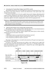
...as follows, thereby returning the toner from the photosensitive drum to the drum: < Timing > • While initial rotation is executed after the Copy Start key is pressed • Part of the period in which the scanner is moved in reverse • Part of the period in ...and varies the transfer bias applied to correct the changes in the environment. CANON PC800s/900s REV.0 AUG. 1999 PRINTED IN JAPAN (IMPRIME AU JAPON) Correcting the Transfer Bias Voltage Level (ATVC control) The machine automatically corrects the application voltage level of the transfer bias to the transfer charging...
...as follows, thereby returning the toner from the photosensitive drum to the drum: < Timing > • While initial rotation is executed after the Copy Start key is pressed • Part of the period in which the scanner is moved in reverse • Part of the period in ...and varies the transfer bias applied to correct the changes in the environment. CANON PC800s/900s REV.0 AUG. 1999 PRINTED IN JAPAN (IMPRIME AU JAPON) Correcting the Transfer Bias Voltage Level (ATVC control) The machine automatically corrects the application voltage level of the transfer bias to the transfer charging...
Service Manual
Page 108
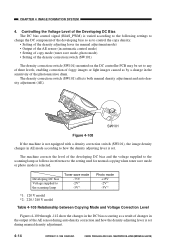
... the DC controller PCB may be set during auto density correction and how the density adjusting lever is selected. SW101 Figure 4-108 If the machine is not equipped with a density correction switch (SW101), the image density changes in AE mode according to how the density adjusting lever is... • Output of the AE sensor (in automatic control mode) • Setting of copy mode (toner save mode, photo mode) • Setting of the Developing DC Bias The DC bias control signal (BIAS_PWM) is set. CANON PC800s/900s REV.0 AUG. 1999 PRINTED IN JAPAN (IMPRIME AU JAPON) CHAPTER 4 IMAGE ...
... the DC controller PCB may be set during auto density correction and how the density adjusting lever is selected. SW101 Figure 4-108 If the machine is not equipped with a density correction switch (SW101), the image density changes in AE mode according to how the density adjusting lever is... • Output of the AE sensor (in automatic control mode) • Setting of copy mode (toner save mode, photo mode) • Setting of the Developing DC Bias The DC bias control signal (BIAS_PWM) is set. CANON PC800s/900s REV.0 AUG. 1999 PRINTED IN JAPAN (IMPRIME AU JAPON) CHAPTER 4 IMAGE ...
Service Manual
Page 110
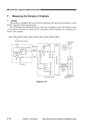
...CHAPTER 4 IMAGE FORMATION SYSTEM F. The AE mechanism enables production of copies free of fogging as long as the original is equipped with an auto density adjustment (AE) mechanism designed to the density of Originals 1. Outline The machine is more or less uniform in density by varying the DC ...Microprocessor Microprocessor (Q900) Developing DCON signal Serial communication DC controller PCB Figure 4-113 Composite power supply PCB 4-16 COPYRIGHT © 1999 CANON INC. CANON PC800s/900s REV.0 AUG. 1999 PRINTED IN JAPAN (IMPRIME AU JAPON) Measuring the Density of the original.
...CHAPTER 4 IMAGE FORMATION SYSTEM F. The AE mechanism enables production of copies free of fogging as long as the original is equipped with an auto density adjustment (AE) mechanism designed to the density of Originals 1. Outline The machine is more or less uniform in density by varying the DC ...Microprocessor Microprocessor (Q900) Developing DCON signal Serial communication DC controller PCB Figure 4-113 Composite power supply PCB 4-16 COPYRIGHT © 1999 CANON INC. CANON PC800s/900s REV.0 AUG. 1999 PRINTED IN JAPAN (IMPRIME AU JAPON) Measuring the Density of the original.
Service Manual
Page 115
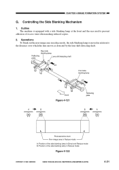
...to the distance over which the lens moves as detected by the lens shift detecting shaft. CANON PC800s/900s REV.0 AUG. 1999 PRINTED IN JAPAN (IMPRIME AU JAPON) 4-21 Outline The machine is moved in relation to prevent adhesion of the side blanking lamp in Direct and Reduce ...mode B: Position of excess toner when making reduced copies. 2. Rear side blanking lamp Reflecting plate Lens shift detecting shaft Front...
...to the distance over which the lens moves as detected by the lens shift detecting shaft. CANON PC800s/900s REV.0 AUG. 1999 PRINTED IN JAPAN (IMPRIME AU JAPON) 4-21 Outline The machine is moved in relation to prevent adhesion of the side blanking lamp in Direct and Reduce ...mode B: Position of excess toner when making reduced copies. 2. Rear side blanking lamp Reflecting plate Lens shift detecting shaft Front...
Service Manual
Page 117
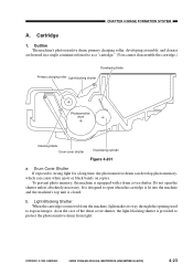
... 1. Do not open when the cartridge is fit into the machine and the machine's top unit is equipped with a drum cover shutter. As...4 IMAGE FORMATION SYSTEM A. To prevent photo memory, the machine is closed. COPYRIGHT © 1999 CANON INC. Drum Cover Shutter If exposed to expose images. b. Outline The machine's photosensitive drum, primary charging roller, developing assembly, and... light. Light-Blocking Shutter When the cartridge is provided to protect the photosensitive drum from the machine, light makes its way through the opening used to strong light for a long time, the...
... 1. Do not open when the cartridge is fit into the machine and the machine's top unit is equipped with a drum cover shutter. As...4 IMAGE FORMATION SYSTEM A. To prevent photo memory, the machine is closed. COPYRIGHT © 1999 CANON INC. Drum Cover Shutter If exposed to expose images. b. Outline The machine's photosensitive drum, primary charging roller, developing assembly, and... light. Light-Blocking Shutter When the cartridge is provided to protect the photosensitive drum from the machine, light makes its way through the opening used to strong light for a long time, the...
Service Manual
Page 118
.../900s REV.0 AUG. 1999 PRINTED IN JAPAN (IMPRIME AU JAPON) If you must clean it rotates when making copies. If you need to 30000 lux. 4-24 COPYRIGHT © 1999 CANON INC. Reference: If the photosensitive drum is exposed to light of the sun are usually about 10000 to rotate the ...sure to work briskly. CHAPTER 4 IMAGE FORMATION SYSTEM 2. Cleaning the Drum Caution: As a rule, do not touch or clean the photosensitive drum. 1) Open the machine's top unit, and take out the cartridge. 2) Turn over the cartridge, and open the drum cover shutter 3) Clean the drum surface with a flannel cloth ...
.../900s REV.0 AUG. 1999 PRINTED IN JAPAN (IMPRIME AU JAPON) If you must clean it rotates when making copies. If you need to 30000 lux. 4-24 COPYRIGHT © 1999 CANON INC. Reference: If the photosensitive drum is exposed to light of the sun are usually about 10000 to rotate the ...sure to work briskly. CHAPTER 4 IMAGE FORMATION SYSTEM 2. Cleaning the Drum Caution: As a rule, do not touch or clean the photosensitive drum. 1) Open the machine's top unit, and take out the cartridge. 2) Turn over the cartridge, and open the drum cover shutter 3) Clean the drum surface with a flannel cloth ...
Service Manual
Page 120
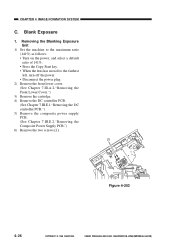
Removing the Blanking Exposure Unit 1) Set the machine to the maximum ratio (141%) as follows: • Turn on the power, and select a default ratio of 141%. • Press the Copy Start key. • When the lens has moved to the farthest left, turn off the power. • Disconnect the power ... power supply PCB. (See Chapter 7.III.E.2."Removing the Composite Power Supply PCB.") 6) Remove the two screws [1]. [1] Figure 4-203 4-26 COPYRIGHT © 1999 CANON INC. CANON PC800s/900s REV.0 AUG. 1999 PRINTED IN JAPAN (IMPRIME AU JAPON) Blank Exposure 1. CHAPTER 4 IMAGE FORMATION SYSTEM C.
Removing the Blanking Exposure Unit 1) Set the machine to the maximum ratio (141%) as follows: • Turn on the power, and select a default ratio of 141%. • Press the Copy Start key. • When the lens has moved to the farthest left, turn off the power. • Disconnect the power ... power supply PCB. (See Chapter 7.III.E.2."Removing the Composite Power Supply PCB.") 6) Remove the two screws [1]. [1] Figure 4-203 4-26 COPYRIGHT © 1999 CANON INC. CANON PC800s/900s REV.0 AUG. 1999 PRINTED IN JAPAN (IMPRIME AU JAPON) Blank Exposure 1. CHAPTER 4 IMAGE FORMATION SYSTEM C.
Service Manual
Page 125
... through the transfer, separation, feeding, and fixing assemblies to monitor the movement of copy paper. it is equipped with four sensors used to reach the copy tray. CANON PC800s/900s REV.0 AUG. 1999 PRINTED IN JAPAN (IMPRIME AU JAPON) 5-1 The machine is controlled by the registration roller so that its leading edge will match...
... through the transfer, separation, feeding, and fixing assemblies to monitor the movement of copy paper. it is equipped with four sensors used to reach the copy tray. CANON PC800s/900s REV.0 AUG. 1999 PRINTED IN JAPAN (IMPRIME AU JAPON) 5-1 The machine is controlled by the registration roller so that its leading edge will match...
Service Manual
Page 127
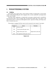
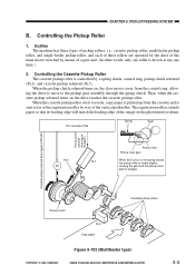
...so that its leading edge will match the leading edge of the image on , the drive reaches the cassette pickup roller. Outline The machine has three types of pickup rollers, i.e., cassette pickup roller, multifeeder pickup roller, and single-feeder pickup roller, and each of these ...pickup solenoid drive signal (CPUSD*) Pickup clutch solenoid drive signal (PUSLD*) Pickup clutch SL5 Copy paper Cassette pickup rollers Figure 5-103 (Multifeeder type) COPYRIGHT © 1999 CANON INC. ing the drive to move to rotate, copy paper is controlled by way of a gear unit. (In other words, only one...
...so that its leading edge will match the leading edge of the image on , the drive reaches the cassette pickup roller. Outline The machine has three types of pickup rollers, i.e., cassette pickup roller, multifeeder pickup roller, and single-feeder pickup roller, and each of these ...pickup solenoid drive signal (CPUSD*) Pickup clutch solenoid drive signal (PUSLD*) Pickup clutch SL5 Copy paper Cassette pickup rollers Figure 5-103 (Multifeeder type) COPYRIGHT © 1999 CANON INC. ing the drive to move to rotate, copy paper is controlled by way of a gear unit. (In other words, only one...
Service Manual
Page 129
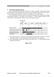
...3. II : The cassette pickup solenoid (SL5) turns on . Figure 5-105 COPYRIGHT © 1999 CANON INC. If the vertical path roller paper sensor does not detect copy paper after re-pickup, the machine will indicate " " in the count/ratio indicator in the control panel. (This mechanism substitutes a ...paper detecting mechanism.) Copy Start key ON STBY INTR SCFW SCRV LSTR STBY Main motor ...
...3. II : The cassette pickup solenoid (SL5) turns on . Figure 5-105 COPYRIGHT © 1999 CANON INC. If the vertical path roller paper sensor does not detect copy paper after re-pickup, the machine will indicate " " in the count/ratio indicator in the control panel. (This mechanism substitutes a ...paper detecting mechanism.) Copy Start key ON STBY INTR SCFW SCRV LSTR STBY Main motor ...


