
Service Manual
Page 3
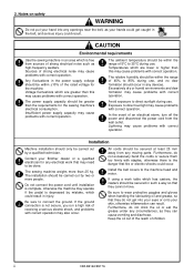
...as your Brother dealer or a qualified electrician for the machine. Excessively dry or humid environments and dew formation may cause problems with correct operation. Installation Machine installation should be carried out by mistake, which are greater than the requirements for the sewing machine's electrical ...be done. Contact your hands could get into any devices. CAUTION Environmental requirements Use the sewing machine in injury. ii CB3-B916A/B917A In the event of children. Do not connect the power cord until installation is complete, otherwise...
...as your Brother dealer or a qualified electrician for the machine. Excessively dry or humid environments and dew formation may cause problems with correct operation. Installation Machine installation should be carried out by mistake, which are greater than the requirements for the sewing machine's electrical ...be done. Contact your hands could get into any devices. CAUTION Environmental requirements Use the sewing machine in injury. ii CB3-B916A/B917A In the event of children. Do not connect the power cord until installation is complete, otherwise...
Service Manual
Page 4
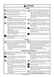
... off as they cannot move. If the machine develops a problem, contact your nearest Brother dealer or a qualified technician. Wait until the motor stops fully before using the machine. Keep the oil out of the reach of the sewing machine should not be extremely careful to carry out... immediately start operating, which result from the wall outlet at the final position after the power is depressed by Brother. CB3-B916A/B917A When turning the machine pulley by mistake, which could result in safe use beforehand. If the power switch needs to wear protective goggles when...
... off as they cannot move. If the machine develops a problem, contact your nearest Brother dealer or a qualified technician. Wait until the motor stops fully before using the machine. Keep the oil out of the reach of the sewing machine should not be extremely careful to carry out... immediately start operating, which result from the wall outlet at the final position after the power is depressed by Brother. CB3-B916A/B917A When turning the machine pulley by mistake, which could result in safe use beforehand. If the power switch needs to wear protective goggles when...
Service Manual
Page 5
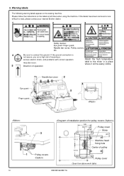
Please follow the instructions on the sewing machine. If the labels have been removed or are difficult to read, please contact your nearest Brother dealer. 1 2 3 Safety devices: Eye guard, Finger guard, Needle bar cover, Pulley covers, etc. 4 Be sure ...Machine head fixing hole Center of operation Attach the high temperature label to connect the ground. If the ground connection is not secure, you run a high risk of receiving a serious electric shock, and problems with correct operation may also occur. 5 Direction of pulley Pulley cover (Seen from above work table) CB3...
Please follow the instructions on the sewing machine. If the labels have been removed or are difficult to read, please contact your nearest Brother dealer. 1 2 3 Safety devices: Eye guard, Finger guard, Needle bar cover, Pulley covers, etc. 4 Be sure ...Machine head fixing hole Center of operation Attach the high temperature label to connect the ground. If the ground connection is not secure, you run a high risk of receiving a serious electric shock, and problems with correct operation may also occur. 5 Direction of pulley Pulley cover (Seen from above work table) CB3...
Service Manual
Page 14
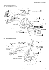
...spring. Button clamp mechanism 1-8-1. Pawl is disengaged and arm is pulled down. Button clamp lift (machine stop) 127s 2 Clutch lever 1. Button clamp descent (sewing start) Button clamp lifter arm Button clamp regulating plate Button clamp arm assembly Spring Button clamp ...lifter 7 connecting rod 9 10 Button clamp presser spring 1. Driving link 1-8-2. CB3-B916A/B917A 8 1-8. MECHANICAL DESCRIPTIONS Button clamp...
...spring. Button clamp mechanism 1-8-1. Pawl is disengaged and arm is pulled down. Button clamp lift (machine stop) 127s 2 Clutch lever 1. Button clamp descent (sewing start) Button clamp lifter arm Button clamp regulating plate Button clamp arm assembly Spring Button clamp ...lifter 7 connecting rod 9 10 Button clamp presser spring 1. Driving link 1-8-2. CB3-B916A/B917A 8 1-8. MECHANICAL DESCRIPTIONS Button clamp...
Service Manual
Page 16
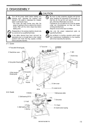
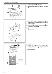
... when handling the lubricating oil and grease, so that they operate correctly before using the machine. Face plate thread guide 6. Bolt 1. Face plate thread guide 4.Sub-tension thread guide...4. Needle 2-2. V-belt 4. Set screw 10. If any cleaning work, otherwise the machine may operate if the pedal is switched off the power switch before starting any safety ... out of the reach of the sewing machine should only be covered by Brother. DISASSEMBLY CAUTION Turn off as a result of the motor's inertia. Any problems in machine operation which could result in injury...
... when handling the lubricating oil and grease, so that they operate correctly before using the machine. Face plate thread guide 6. Bolt 1. Face plate thread guide 4.Sub-tension thread guide...4. Needle 2-2. V-belt 4. Set screw 10. If any cleaning work, otherwise the machine may operate if the pedal is switched off the power switch before starting any safety ... out of the reach of the sewing machine should only be covered by Brother. DISASSEMBLY CAUTION Turn off as a result of the motor's inertia. Any problems in machine operation which could result in injury...
Service Manual
Page 21
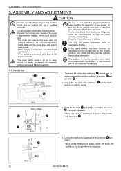
...and adjustment of the sewing machine should face up and be inserted through the needle bar drive lever and set collar gently to the machine will keep turning ...Brother. Turn off as specified by the warranty. 3-1. Wait until the motor stops fully before starting work. • When carrying out inspection, adjustment and maintenance • When replacing consumable parts such as they operate correctly before using the machine... grease 1. Any problems in machine operation which could result in injury. * The motor will not be excessive. 303s Mark 15 CB3-B916A/B917A If the power...
...and adjustment of the sewing machine should face up and be inserted through the needle bar drive lever and set collar gently to the machine will keep turning ...Brother. Turn off as specified by the warranty. 3-1. Wait until the motor stops fully before starting work. • When carrying out inspection, adjustment and maintenance • When replacing consumable parts such as they operate correctly before using the machine... grease 1. Any problems in machine operation which could result in injury. * The motor will not be excessive. 303s Mark 15 CB3-B916A/B917A If the power...
Service Manual
Page 25
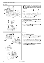
... Reference Reference a line b line 2 mm 316s Thinner part 1. Fit the loop spreader to the loop spreader guide and to the 3. Tilt the sewing machine downward. 9. to the roller and to , and then install to the loop spreader link . 317s 318s Needle lowest position 319s Needle 320s 0.3 -... spreader groove cam until the clearance between the loop spreader and the needle is extended farthest outward. 10. Contact lightly 19 321s CB3-B916A/B917A Attach the loop spreader link the loop spreader groove cam frame. Place the thread handler triangular cam onto the looper setting...
... Reference Reference a line b line 2 mm 316s Thinner part 1. Fit the loop spreader to the loop spreader guide and to the 3. Tilt the sewing machine downward. 9. to the roller and to , and then install to the loop spreader link . 317s 318s Needle lowest position 319s Needle 320s 0.3 -... spreader groove cam until the clearance between the loop spreader and the needle is extended farthest outward. 10. Contact lightly 19 321s CB3-B916A/B917A Attach the loop spreader link the loop spreader groove cam frame. Place the thread handler triangular cam onto the looper setting...
Service Manual
Page 28
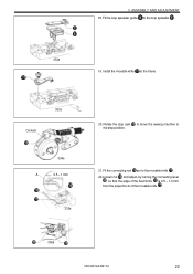
Fit the loop spreader guide to the frame 333s Contact 334s A 0.5 - 1 mm 335s 20. Install the movable knife to the loop spreader . 332s 19. 3. Rotate the stop position. 21. Fit the connecting rod pin to the stop cam to move the sewing machine to the movable knife . 22.Loosen nut and adjust, by turning the connecting lever , so that the edge of the fixed knife is 0.5 - 1.0 mm from the projection A of the movable knife . 336s CB3-B916A/B917A 22 ASSEMBLY AND ADJUSTMENT 18.
Fit the loop spreader guide to the frame 333s Contact 334s A 0.5 - 1 mm 335s 20. Install the movable knife to the loop spreader . 332s 19. 3. Rotate the stop position. 21. Fit the connecting rod pin to the stop cam to move the sewing machine to the movable knife . 22.Loosen nut and adjust, by turning the connecting lever , so that the edge of the fixed knife is 0.5 - 1.0 mm from the projection A of the movable knife . 336s CB3-B916A/B917A 22 ASSEMBLY AND ADJUSTMENT 18.
Service Manual
Page 29
ASSEMBLY AND ADJUSTMENT 23. Put the sewing machine in the stop cam and adjust the feed plate so that the needle will pass through at the four corners of the square hole of entry 341s 23 CB3-B916A/B917A Loosen the nut and adjust the indicator plate to the 3.5 mark on the vertical feed...
ASSEMBLY AND ADJUSTMENT 23. Put the sewing machine in the stop cam and adjust the feed plate so that the needle will pass through at the four corners of the square hole of entry 341s 23 CB3-B916A/B917A Loosen the nut and adjust the indicator plate to the 3.5 mark on the vertical feed...
Service Manual
Page 31
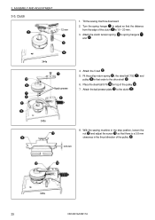
...clutch tension spring to the clutch . 345s 8. Attach the ball presser plate to spring hangers and . 344s Apply grease 4. Attach the V-belt . 5. With the sewing machine in the stop position, loosen the nut and adjust the screw so that there is a 0.8 mm clearance in that the distance from the edge of... the pulley . 0.8 mm 346s 25 CB3-B916A/B917A Turn the spring hanger to adjust so that order to the drive shaft . 6. ASSEMBLY AND ADJUSTMENT 3-5. Place the steel ball 5/16 on ...
...clutch tension spring to the clutch . 345s 8. Attach the ball presser plate to spring hangers and . 344s Apply grease 4. Attach the V-belt . 5. With the sewing machine in the stop position, loosen the nut and adjust the screw so that there is a 0.8 mm clearance in that the distance from the edge of... the pulley . 0.8 mm 346s 25 CB3-B916A/B917A Turn the spring hanger to adjust so that order to the drive shaft . 6. ASSEMBLY AND ADJUSTMENT 3-5. Place the steel ball 5/16 on ...
Service Manual
Page 32
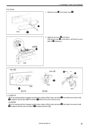
... stopped and the button clamp is aligned with take -in A 349s 350s 351s B917A B916A 3. ASSEMBLY AND ADJUSTMENT 1. 3-6. For B916A When the sewing machine is stopped and the button clamp is lifted, loosen set screw to the frame. (With the top cover on the frame, it will fit well ... the looper cover . 2. Cover 347s 3. Attach the cover to adjust so that the take -in A. , and rotate the eccentric shaft , and rotate the eccentric shaft CB3-B916A/B917A 26
... stopped and the button clamp is aligned with take -in A 349s 350s 351s B917A B916A 3. ASSEMBLY AND ADJUSTMENT 1. 3-6. For B916A When the sewing machine is stopped and the button clamp is lifted, loosen set screw to the frame. (With the top cover on the frame, it will fit well ... the looper cover . 2. Cover 347s 3. Attach the cover to adjust so that the take -in A. , and rotate the eccentric shaft , and rotate the eccentric shaft CB3-B916A/B917A 26
Service Manual
Page 34
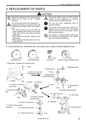
Steel ball 5/16 3. Pulley tilt the sewing machine 8. Number of the sewing machine should only be covered by Brother. Loosen the stop screw 5. REPLACEMENT OF PARTS 4.REPLACEMENT OF PARTS CAUTION Assembly and adjustment of stitches adjustment cam 23....observe all safety precautions. Pulley return spring 4. Needle 405s 16. Loosen the stop screw 410s 409s CB3-B916A/B917A 28 4. Wait until the motor stops fully before using the machine. Tilt the sewing machine downward 22. Clutch tension spring 11. Loose the screw 21. Any problems in numerical order. ...
Steel ball 5/16 3. Pulley tilt the sewing machine 8. Number of the sewing machine should only be covered by Brother. Loosen the stop screw 5. REPLACEMENT OF PARTS 4.REPLACEMENT OF PARTS CAUTION Assembly and adjustment of stitches adjustment cam 23....observe all safety precautions. Pulley return spring 4. Needle 405s 16. Loosen the stop screw 410s 409s CB3-B916A/B917A 28 4. Wait until the motor stops fully before using the machine. Tilt the sewing machine downward 22. Clutch tension spring 11. Loose the screw 21. Any problems in numerical order. ...
Service Manual
Page 36
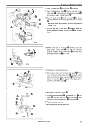
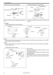
...and . *Align the center of the worm gear with a screwdriver, adjust so that the backlash of the cam shaft . Backlash becomes smaller 424s CB3-B916A/B917A 30 should align with the cam positioning pin . The screw flat of the rotating shaft . 7. The mark of the clutch. 423s 0.3...cam shaft by adjusting the number of the stop position. Place end A of stitches control lever . 422s Mark 8. REPLACEMENT OF PARTS 6. Move the sewing machine to the screw flat of the worm and worm gear becomes 0.3 mm at this time. A 421s Screw flat 4. By loosening the worm , and...
...and . *Align the center of the worm gear with a screwdriver, adjust so that the backlash of the cam shaft . Backlash becomes smaller 424s CB3-B916A/B917A 30 should align with the cam positioning pin . The screw flat of the rotating shaft . 7. The mark of the clutch. 423s 0.3...cam shaft by adjusting the number of the stop position. Place end A of stitches control lever . 422s Mark 8. REPLACEMENT OF PARTS 6. Move the sewing machine to the screw flat of the worm and worm gear becomes 0.3 mm at this time. A 421s Screw flat 4. By loosening the worm , and...
Service Manual
Page 37
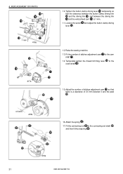
... the 15. 4. Loosen the screw and adjust the button clamp driving lever . 12. REPLACEMENT OF PARTS 1 mm 1 mm 416s 417s 0.5 mm 418s 10. Raise the sewing machine. 13. Adjust the number of stitches adjustment cam to the connecting rod shaft , and then fit the snap ring . 419s 31...
... the 15. 4. Loosen the screw and adjust the button clamp driving lever . 12. REPLACEMENT OF PARTS 1 mm 1 mm 416s 417s 0.5 mm 418s 10. Raise the sewing machine. 13. Adjust the number of stitches adjustment cam to the connecting rod shaft , and then fit the snap ring . 419s 31...
Service Manual
Page 38
... is facing upward, and then secure it by rotating the stop cam two or three times. 420s 0.5 mm 425s 0 mm 426s 22. Tilt the sewing machine downward. 24. Then move the button clamp driving lever to adjust so that the clearance between the stitch length control lever and the stitch length... shaft into the oval hole in the bed. 19. With the rear part of [Brake] (P.39). 21. Attach the needle and installation bolt. 427s CB3-B916A/B917A 32 Turn the brake shaft until the screw is completed, tighten the screw . 25. REPLACEMENT OF PARTS 18. Insert the brake lever shaft...
... is facing upward, and then secure it by rotating the stop cam two or three times. 420s 0.5 mm 425s 0 mm 426s 22. Tilt the sewing machine downward. 24. Then move the button clamp driving lever to adjust so that the clearance between the stitch length control lever and the stitch length... shaft into the oval hole in the bed. 19. With the rear part of [Brake] (P.39). 21. Attach the needle and installation bolt. 427s CB3-B916A/B917A 32 Turn the brake shaft until the screw is completed, tighten the screw . 25. REPLACEMENT OF PARTS 18. Insert the brake lever shaft...
Service Manual
Page 39
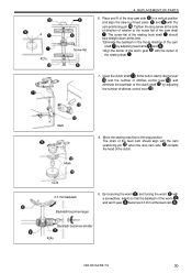
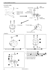
... installation bolt. 427s 33 CB3-B916A/B917A Install the pulley return spring , the steel ball 7/32 , the pulley , the steel ball 5/16 , and the belt , and install the ball presser plate to pry 431s 432s 1. REPLACEMENT OF PARTS 4-2.Cushion rubber < Disassembly > 1.Bolt 2.Open the cover and tilt the sewing machine 5.Steel ball 5/16...
... installation bolt. 427s 33 CB3-B916A/B917A Install the pulley return spring , the steel ball 7/32 , the pulley , the steel ball 5/16 , and the belt , and install the ball presser plate to pry 431s 432s 1. REPLACEMENT OF PARTS 4-2.Cushion rubber < Disassembly > 1.Bolt 2.Open the cover and tilt the sewing machine 5.Steel ball 5/16...
Service Manual
Page 40
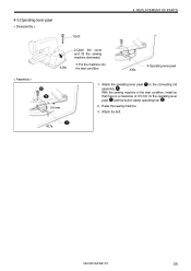
Attach the operating lever pawl to the connecting rod assembly . With the sewing machine in the start condition. 436s 4.Operating lever pawl 0.6 mm 1. Raise the sewing machine. 3. REPLACEMENT OF PARTS < Assembly > 428s 2.Open the cover and tilt the sewing machine downward. 3.Put the machine into the start condition, install so that there is a clearance of 0.5 mm for the operating lever pawl and the button clamp operating fork . 2. Attach the bolt. 437s CB3-B916A/B917A 34 4-3.Operating lever pawl < Disassembly > 1.Bolt 4.
Attach the operating lever pawl to the connecting rod assembly . With the sewing machine in the start condition. 436s 4.Operating lever pawl 0.6 mm 1. Raise the sewing machine. 3. REPLACEMENT OF PARTS < Assembly > 428s 2.Open the cover and tilt the sewing machine downward. 3.Put the machine into the start condition, install so that there is a clearance of 0.5 mm for the operating lever pawl and the button clamp operating fork . 2. Attach the bolt. 437s CB3-B916A/B917A 34 4-3.Operating lever pawl < Disassembly > 1.Bolt 4.
Service Manual
Page 41
Be sure to its closest point to you by Brother. Use only the proper replacement parts as the loopers and knife. the center of the needle should be absolutely sure to re-install them to ... have been removed, be approximately 2 mm. 35 CB3-B916A/B917A Wait until it is at the center of the motor's inertia. If any circumstances, as a result of the needle by a qualified technician. Adjust the tip of the sewing machine should be extremely careful to the machine will keep turning even after the power is...
Be sure to its closest point to you by Brother. Use only the proper replacement parts as the loopers and knife. the center of the needle should be absolutely sure to re-install them to ... have been removed, be approximately 2 mm. 35 CB3-B916A/B917A Wait until it is at the center of the motor's inertia. If any circumstances, as a result of the needle by a qualified technician. Adjust the tip of the sewing machine should be extremely careful to the machine will keep turning even after the power is...
Service Manual
Page 42
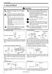
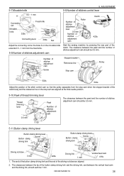
... of the stitch control cam so that the pulley separates from the fixed knife. 5-9.Number of stitches adjustment cam Start the sewing machine by pressing the rear part of the clutch. CB3-B916A/B917A 36 5-7.Movable knife 5. The clearance between the pawl and the number of the button clamp driving fork and the...
... of the stitch control cam so that the pulley separates from the fixed knife. 5-9.Number of stitches adjustment cam Start the sewing machine by pressing the rear part of the clutch. CB3-B916A/B917A 36 5-7.Movable knife 5. The clearance between the pawl and the number of the button clamp driving fork and the...
Service Manual
Page 43
...plate Nut Screw 424s 346s Adjust the feed cam to lift the button clamp, the eccentric shaft should be 0.6 mm. 506s 0.6 mm 37 CB3-B916A/B917A B916A When the presser lifter pedal is depressed to obtain a backlash of the frame hole. ADJUSTMENT 5-12.Worm and worm gear ... 505s B917A / B916A Depress the starting pedal and rotate the pulley two or three times (starting condition). be 0.8 mm. 5-14.Slider < With the sewing machine in the stop condition > Take-in B Take-in A Eccentric shaft Set screw Slider B 349s Slider B 350s 351s B917A B916A B917A When the presser ...
...plate Nut Screw 424s 346s Adjust the feed cam to lift the button clamp, the eccentric shaft should be 0.6 mm. 506s 0.6 mm 37 CB3-B916A/B917A B916A When the presser lifter pedal is depressed to obtain a backlash of the frame hole. ADJUSTMENT 5-12.Worm and worm gear ... 505s B917A / B916A Depress the starting pedal and rotate the pulley two or three times (starting condition). be 0.8 mm. 5-14.Slider < With the sewing machine in the stop condition > Take-in B Take-in A Eccentric shaft Set screw Slider B 349s Slider B 350s 351s B917A B916A B917A When the presser ...


